Radio Boulevard
Western Historic Radio Museum


RCA's Amazing AR-88 Series of Receivers

Part 2

The Triple Diversity Receivers
The AR-88 and Russian Hams
AR-88 Series Serial Number Analysis and Log
Operational and Modification Caveats
Restoration Suggestions


1950 SC-88 (aka R-320/FRC) a component receiver of OA-58A/FRC - SN: 214


The Triple Diversity Receivers

A Brief History of Diversity Reception - In the mid-1920s, two RCA engineers, Harold Beverage and H. O. Peterson, noticed that when they listened to Peterson's radio receiver, located in his home, over a telephone line to the RCA station in New York and simultaneously listened to the same station on RCA receivers, the two separated station antennas and receivers showed different fading characteristics. The two stations were about a half of a mile apart. Beverage and Peterson continued with several experiments and over the next few years developed "Diversity Reception" - a method of reducing or eliminating fading radio signals.


Photo Above
:  H.O. Peterson (left) and H.H. Beverage testing and adjusting the triple diversity receivers at Riverhead, Long Island, New York. 
Photo from August, 1933 - Radio News

Just what causes radio signals to fade? When a received radio signal originates from beyond the horizon it must either have traveled along the curvature of the earth as longwave signals do or it must have been refracted through the ionosphere as shortwave signals do. The ionosphere is made up of several layers that refract shortwave radio signals from different distances above the earth depending on the time of day, the time of year and where in the sunspot cycle we happen to be. Many times, radio waves are refracted from several layers simultaneously. The radio wave is then returned to earth having traveled different paths and different distances and consequently arriving at the receiver's antenna at slightly different times. The radio signal then has several components that will set-up phase differences along a single antenna and when these phases conflict, signal cancellation occurs. When the phases add, the signal increases. Since the ionosphere is in a constant flux, likewise the radio signal refraction varies and we see the result as fading radio signals.

In addition to multipath-distance refraction causing phase conflicts on a single antenna resulting in fading, other signal anomalies occur. Wave rotation through the ionosphere will cause polarization changes that can affect the signal versus antenna relationship. Selective fading is where certain frequency components of a radio signal are refracted differently through the ionosphere resulting in a portion of the signal fading while other components of the radio wave are not affected. 

Beverage and Peterson analyzed strip chart recordings of several receivers with multiple antennas and noticed that larger arrays only made the fading worse. The problem was the phase conflicts on a single antenna - no matter how large that single antenna was. To eliminate phase conflicts required widely separated antennas that would see different phases of the received signals and a way to combine these antennas into a single signal with no fading.     >>>

 >>>    Using multiple antennas and receivers was how Beverage and Peterson solved the fading problem. By allowing the Antenna to Receiver phase difference to remain separated until each receiver's detector circuit the individual fading response was maintained. At the detector, the signal is converted to an audio frequency and the different phases become irrelevant. Combining the multiple detector outputs was simple since each was basically a diode and their outputs could be tied together. Now, whichever signal was strongest, dominated the multiple detector output and fading was greatly reduced.

It was noted that a gain control of the entire system was lacking and many times some of the fading characteristics were passed through the receivers due to additive phase combining on one antenna. Using the AVC circuits as a feedback gain control allowed all of the receivers to share the same AVC line. This then allowed the receiver with the highest level response to the desired signal to control the AVC line and therefore the overall receiver gain. Fading was under control and practically eliminated as each receiver seamlessly controlled the AVC control based on which one was receiving the signal best.

Beverage and Peterson eventually decided that three receivers were the ideal combination. Dual Diversity would reduce fading by about 90% while Triple Diversity reduced fading by 99%, or almost total elimination of fading. Antenna separation was specified at 1000 feet for commercial and some military installations. However, usable Diversity Effect can be experienced with as little as one wavelength of antenna separation. This type of diversity reception was generally called "Space Diversity" since it depended on antenna separation for diversity effect. By 1930, RCA had 26 Triple Diversity Receivers at Rivershead, NY servicing over 40 different countries around the world with Radiogram communications. The received diversity signals were multiplexed and sent down the telephone lines to the RCA offices in New York City where they were "machine" copied and then sent on to their destination.

Diversity reception was the standard for world-wide reliable communications from 1930 up into the 1970s, both in military applications and in commercial use. By the late-1970s, telephone/fax technology advanced to the point where telegrams were no longer the only cheap method of communications. At that time, large scale diversity installations with multiple receivers became a financial burden since the world-wide radio-telegram communications systems that had paid for their necessary existence had become obsolete. 

DR-89, RDM and OA-58A/FRC


photo above: The receiving station at Vilnius, Lithuania, ca. late-1950s. The two center racks are RCA DR-89 Triple Diversity Receivers. The end racks carry Russian-made equipment (predecessor to the Russian R-250 receiver called "Klen" along with support equipment probably for FSK/DFSK.) The receivers were used to monitor various types of signals and select SW stations to be "jammed." 
Photo from:  www.radiojamming.info  


DR-89 - This was RCA's commercial triple diversity receiver used in many of the RCA and RMCA coastal stations and in other stations where reliable message copy was absolutely necessary. The rack was seven feet tall and housed three AR-88F receivers. The rack also included a Tone Keyer. This unit was required because, when operating in diversity, the receiver's BFO cannot be used. For proper diversity operation all of the receivers must be operating in AVC and, if the BFO was on, it would capture the detectors, rendering the AVC inoperative and spoiling any diversity action. Therefore another method was devised to copy CW or RTTY in diversity - the Tone Keyer. >>>

>>>  The Tone Keyer uses the signal amplitude variations of a CW signal received without BFO action and uses that amplitude variation to "key" a circuit whose output is a pure tone representative of the incoming CW signal. No background noise or random minor interferences make it through the Tone Keyer. These devices were mainly used for machine copy of CW (or high-speed mechanically sent CW or RTTY) and only occasionally for human copy of CW.

Also included in the rack was a Monitoring Unit. This device picked the signal up from between the 1st and 2nd IF amplifiers ("MONITOR" output on rear of chassis) of each AR-88F and routed it through its own IF section with detector-AVC , BFO and Audio Output. This allowed the operator to monitor the signals without disturbing the diversity set-up of the receivers. The three meters monitored the Diode Load current that was routed to the Tone Keyer.

Before actual reception of signals in diversity, the DR-89 had to be "balanced." This required the operator to accurately tune in the desired station (or a test signal) on all three receivers. Then, using the "DIVERSITY IF GAIN" control on each receiver, the operator would adjust the output of each receiver to be equal as measured on the Meters of the Monitoring Unit (although the meters are connected through the Tone Keyer.) This compensated for differences in individual receiver/antenna overall gain and then allowed of equal diversity action of the three combined receivers.

At the bottom of the rack is the speaker panel which allowed monitoring of individual receivers or one selected receiver as the diversity audio output of all three receivers. Also, at the very bottom was a power supply to operate the Monitoring Unit and at the very top of the rack was a patch panel for various antenna inputs.

Other Triple Diversity Receivers

RDM - U.S. Navy designation for the DR-89. The Navy version is identical to the RCA DR-89. Mostly used during WWII. The receivers are identified as CRV-46246B and are either AR-88F or later CR-88A models. The photos show the RDM. Documentation became "Unclassified" in June 1947.

OA-58A/FRC - Signal Corps Triple Diversity set-up using three SC-88 (Signal Corps designation is R-320/FRC) receivers from 1949-1950. The auxiliary components are slightly changed in appearance but have same design and function as in the DR-89 and the RDM. The R-320/FRC is an updated version of the AR-88F. A photo of the OA-58A/FRC is shown below.


NAVY  RDM RECEIVER


REAR VIEW OF THE NAVY RDM


SIGNAL CORPS  OA-58A/FRC

Diversity Receiver Components


Shown in the photo left is the Tone Keyer from the RDM. This unit allowed the Triple Diversity Receivers to operate in diversity and receive CW/RTTY signals.

Shown in the photo right is the Loudspeaker Assembly. This unit provided the operator with the ability to monitor the audio from the three receivers operating in combined diversity or to monitor each receiver individually.

Shown in the photo left is the Monitoring Unit. This device had its own IF section, Detector, BFO and Audio Output. The Monitoring Unit was connected to the "Monitor" output on each receiver which was a connection between the 1st IF amplifier and the 2nd IF amplifier. This allowed the operator to monitor each receiver individually without upsetting the diversity reception. Separate power supply at bottom of rack.

SC-88  -  SIGNAL CORPS - R-320/FRC

Shown in the photo to the right is the SC-88 receiver. It's actual designation is R-320/FRC and it was used in the Signal Corps OA-58A/FRC triple diversity receiver. The SC-88 is one of the last of the AR-88 versions produced with most receivers built between 1949 and 1950. The SC-88 receiver has the later feature of the Crystal Phasing control on the front panel with smaller knobs for the RF and AF Gain. The SC-88 was the first version to have the "Band-in-Use" Dial Mask. The mask has the frequency ranges printed on it so the frequency ranges were eliminated from the front panel RANGE switch nomenclature. The receivers were MFP'd and the chassis appears gold colored because of it. Note the small knob on the lower right of the panel, between and slightly lower than the SELECTIVITY and AVC-MAN controls. This is the "DIVERSITY IF GAIN" control found on ALL receivers that were used in the RCA Triple Diversity Receivers. All of the SC-88 receivers were originally rack mounted configuration. Additionally, all known SC-88 examples have (or had) the Signal Corps R-320/FRC metal tag on the front panel, top-center and this is the only place that the serial number was stamped.

One obvious change from the typical AR-88 can be seen in the photo below-left showing the SC-88 chassis. There are two individual filter capacitors on top of the chassis and one filter capacitor under the chassis. These were to replace the earlier filter capacitor unit that had all three filter capacitors inside the same can. This may have been more of an economics issue besides reliability. With the failure of one filter capacitor the entire unit had to be replaced in the earlier receivers. Later receivers, like the SC-88, only require that the defective capacitor be replaced. Another change is the BFO can which now doesn't have the removable cap on the top of the can. Also, the BFO is now coupled to the third IF amplifier grid with a 10pf capacitor (rather than using electrostatic coupling.) Additionally, the mounting of the main dial lamp is now on a bracket rather than clipped to the front plate of the gear box and the lamp shield for the illuminated ID plate has been eliminated. Located just behind the 1st IF transformer is the plug-in, HC-6 type, 455kc crystal for the crystal filter. In the earlier models of the AR-88 series, the crystal was mounted under the chassis. It was placed in a clip but was hard-wired into the circuit. The alignment adjustments for the 1st RF/ANT stage are now mounted on top of the chassis (under the RF cover) rather than having to access them through holes in the rear of the chassis. The "plunger type" trimmer capacitors are replaced with standard trimmer capacitors. "Cool Ohm" resistors are used in place of "Ohmite" resistors. Since a dial mask is used, the main dial is not alternating black and yellow band scales like the standard AR-88. Instead, the dial is entirely yellow. The front panel is painted ultra-fine wrinkle finish black.

The total production of SC-88 receivers was quite small with estimates usually being around 300 receivers built. It's interesting that in the early sixties, Fair Radio Sales offered R-320/SC-88 receivers for sale (listed in Catalogs Spring-Summer '62 and Fall '62-Winter'63.). The price was $185 checked for operation and $170 if unchecked. A "new" cabinet was offered for an extra $10. Shipping weight was 98 lbs but the receiver actually weighs about 75 pounds. The availability didn't last and by a few catalogs later the SC-88 was replaced with AR-88s for sale at $175 checked for operation. It's probable that most of the surviving SC-88 receivers ended up being purchased from Fair Radio Sales. The U.S. Army Signal Corps manual for the R-320/FRC is TM11-899 and copies of this manual are still available from Fair Radio.   >>>


SC-88 (R-320/FRC) version of the AR-88F from 1950 - SN: 214

The SN: 214 Story - I first saw SC-88 SN: 214 in 1975. It was on a shelf above the workbench in the workshop of my old radio collector friend, Fred Winkler, who lived in Moundhouse, Nevada (outside Carson City.) Fred had purchased the RCA SC-88 "surplus" several years before (undoubtedly from Fair Radio) and used it for listening to KVLV from Fallon, Nevada. Over the years, I'd always see the old SC-88 sitting there on the shelf accumulating more and more dust but still playing strong. Fred had a house fire in 1984 that destroyed most of his radio collection. His detached workshop was undamaged, though. After Fred rebuilt his house, for some reason he asked me if I wanted his old SC-88 and, of course, I was thrilled to obtain the receiver that I had admired over the past decade. It was all original and in very nice condition under the layers of dust. But, it was missing the 455kc crystal (a new 455kc has since been installed.) Also, it had apparently been constantly tuned during its past Signal Corps duty because the front bearing support in the gearbox was severely worn. I installed a panel-mounted 0.25" shaft bushing to support the front end of the tuning shaft and that worked great. I did an alignment after installing the 455kc crystal. Nowadays, I've had SC-88 serial number 214 for over 35 years and it still performs great and often reminds me of old Fred who became an SK in 2002.

The photos below show the top of the SC-88 chassis and the underneath of the chassis. All shields are shown installed except for the bottom cover that had to be removed for the photograph. The shields kept the LO radiation at an extremely low level so the receivers could operate in the presence of multiple receiver installations with no interference generated or received (as in the OA-58A/FRC.) What's immediately apparent is that the SC-88 was given a typical Signal Corps "heavy duty" MFP treatment,...both on top of the chassis and even underneath,...even though there's a bottom cover that almost seals the underside of the chassis. This thick coating of fungicide treatment has probably helped to preserve the metal parts over the years,...that, and the fact that the receiver has been in dry, dry Northwestern Nevada near the east slope of the Sierra for over half-a-century.


The AR-88 and the Russian Hams

Many of the UA and UK stations worked on CW 20M in the nineteen-sixties and seventies were using the AR-88 for their station receivers. Most of the QSL cards from these Russian hams would just say that the receiver was a "14 tube Superhet" but we all knew that meant they were using an AR-88.

The first release of surplus AR-88s to the Russian hams was in the late-1950s. The military was stocked with the KV-M receivers that were Russian-built close-copies of the Hammarlund Super Pro BC-779. They also had Krot/M receivers that were Russian-built copies of the Nazi E-52 Koein and the early version of the Russian R-250 called the AS-1 and AS-2. As a result of the quantities of various types of receivers available, the military released the AR-88, DR-89 and original Nazi E-52 receivers to the Ministry of Communications where they ultimately became available to hams and ham clubs. Later, in the sixties, the Soviet military had the R-250, R-250M/KMPU/Kalina/Step and later still, the R-250M2/R-670M/KMPU-M. A rack with two R-250M was designated as KMPU and a rack with two R-250M2 or 670M was designed as KMPU-M.  >>>
 

photo right: UA1OSM  Serge with his AR-88F mounted in a cabinet ca: late-sixties

photo left: Ernst Krenkel, famous Russian polar explorer and radioman for many polar expeditions. Krenkel Observatory in Franz Josef Land is named after him. Krenkel wrote a book on radio, was featured in several radio magazines, worked in the radio industry and in the scientific instrument industry. He was awarded several honors from the USSR (Order of Lenin, Hero of the USSR.) Krenkel was a very active radio amateur. His calls were U3AA, UA3AA and the call shown on the photo, RAEM (written as "RaeM" - the photo was sent to LA2JE as a QSL.) The receiver is an AR-88F and the transmitter is a BC-610. Note that Krenkel is using an enclosed key.    Photo from Valery Mirgorodsky, Pres. Russian Antique Radio Club


photo right
: UAØSQ - op "Vlad" with his AR-88 ca: 1970 (note the gloss panel)    photo from UA1OSM

>>> With much more advanced receivers planned, the Soviet military felt by the late-1950s the AR-88 was beginning to show its age and its release into the hands of hams would pose no military communications security problems. As even more advanced receivers became available to the military by the mid-sixties the last of the surplus AR-88s were disposed of. Certainly, by the seventies, many of the AR-88s that had been released earlier were now exchanging hands between the Russian hams.

Many Russian hams started in amateur radio by becoming an SWL (Short Wave Listener) at a ham club. This usually required the aspiring ham to confirm reception of several ham stations in the CW mode by obtaining QSL cards from the station copied. That was why it was so important for USA-hams to actually respond to the SWL QSL cards they received - it helped the aspiring ham prove that he could copy "on-the-air-sent" CW, issue accurate, dated signal reports in the form of a QSL card and was able to receive a confirmation QSL card "via the Bureau." Often, once the license was issued, the new ham operated at a club station until he was able to buy or build his own equipment. 

Many UA and UK stations worked on 20M CW in the sixties and seventies were club stations. However, many of the AR-88s also were in the hands of ham stations owned by individuals. Nowadays, most of the AR-88s in Russia are either in the hands of collector-hams or in various technical or radio museums.

Thanks to Serge UA1OSM for the details on Russian military receivers and the AR-88 history in Russia.


AR-88 Series - Serial Numbers and Serial Number Log

Alan Ford's SN Analysis

The typical AR-88 serial number contains six digits that include leading zeros. However, the six digits are not a numerical representation of when in the production cycle the receiver was manufactured. It appears that the most significant digit of the serial number (sixth digit from the right) represents which RCA plant built the receiver. This seems to be true because only two digits are used in the most significant place, "0" or "1." This could represent the plants at Camden and Bloomington. Canadian AR-88LFs built in Montreal are all serialized with a "C" in the most significant place (as a prefix.) However, many AR-88 receivers are serialized with only five digits. Could the "blank" in the sixth position signify another assembly plant?   (Several sources indicate that the Grigsby-Grunow Company was used as a contractor for AR-88 assembly but that doesn't seem possible since this company was bankrupt and in receivership in December 1934. It might be possible that some confusion exists between the two "Majestic" companies. Grigsby-Grunow used "Majestic" as their trade name from the late twenties up to 1934. In 1937, "Majestic Radio and Television Company" was formed. This Majestic R&TV company had no connections to the earlier GG Majestic. It may be possible that the wartime contacts were partially built by this later "Majestic" - Majestic Radio & TV Co. - although there's no official documentation of the connection and all references to Majestic are hearsay. If a "Majestic" was involved it has mistakenly been identified as the bankrupt and "long-gone" Grigsby-Grunow company.*)    This then accounts for the four possibilities used as the most significant place, "C," "blank," "0" or "1."

Here are some observations by Alan Ford, VK2DRR, regarding AR-88D and AR-88LF models...

1. The 6th digit from the right (where it exists) is never more than 1
2. The 5th digit from the right is also never more than 1 (on AR-88D, AR-88F or AR-88LF)
3. If we assume that the first of the 6 digits is not an actual serial but stands for the plant of manufacture, that would give two plants - Camden, NJ and Bloomington, IN. The "blank" sixth position could signify a third assembly plant. 
4. It would appear that all LFs were made in Canada and have the prefix "C" in their serial numbers.

The serial numbers reported so far suggests that at least 14,215 receivers were made. Although the 5 digit system allows for 99,999 receivers, so far there are none at all from the 20,000 upwards (you'd expect even this small sample to be fairly random) so I think the theory that 100,000 receivers were made cannot be correct.

Alan has concentrated on the AR-88D, AR-88F and AR-88LF models of the receiver and their serial number assignments.

* WHRM-Radio Boulevard observation and opinion

WHRM SN Observations

Early Serial Number Sequences - When looking at the fifth digit from the right, this digit indicates the model of the receiver. Looking at the WHRM serial number log it is apparent that all AR-88F versions use a "1" as this digit. As can be seen in the serial number log, all AR-88F receivers have "1" as the fifth digit. The early (Camden-built) CR-91 receivers will have "5" in the fifth digit to indicate CR-91. It is impossible that 50,000 CR-91 receivers were built and therefore the "5" must represent the model designation. As can be seen in the serial number log, the eight reported CR-91 receivers all have "05" as the sixth and fifth digit indicating that these receivers were all built in Camden and are all CR-91 versions. I believe that RCA used the same imbedded information in their earlier commercial receiver, the AR-60. One can see from analysis of the AR-60 serial numbers that the various versions had different sequences of number combinations used to show model type and possibly manufacturing plant. From the AR-60 analysis it seems likely that RCA was continuing to imbed information into their serial numbers with the AR-88 series. The exception is with the high production AR-88D receivers. Most AR-88D receivers use a "0" in the fifth position but it appears that late in production the fifth digit on these AR-88D receivers becomes a 1 when the production exceeded 10,000 receivers. It's also possible that RCA considered the AR-88D to be the "standard model" and therefore the fifth digit was always part of the serial number and was never embedded model information. However, the model sub-variations use the fifth digit as identification.

The sixth digit "1" probably indicates that the receiver was built somewhere other than Camden,...probably Bloomington but that's just a supposition. It appears that the serial numbers are specific to the runs at Bloomington and are not combined with receivers built at Camden. Note that all of the Bloomington SNs are low with the highest numbers not exceeding 2000. Additionally, all receivers from Bloomington seem to be the later-style with silk-screened panels and alternating black and yellow tuning dials.

Not long after WWII ended, RCA made some upgrades to the AR-88 series of receivers. The new receivers have different designations as CR-88, CR-88A, CR-88B, CR91A and SC-88. The ultimate use and the demand for a high quality communications receiver had certainly changed and production quantity was much less than with the WWII versions of the receiver. The serial number sequence changed with the introduction of these updated receivers.

Later Serial Number Sequences - The CR-88 and CR-88A use the same six digit format that the AR-88D had used but it appears that the four digits that comprise the actual identification of the receiver reused some of the same numbers that were assigned during WWII. Apparently RCA believed that there wouldn't be any confusion since none of the WWII versions were supposed to be returned from overseas and the new CR-88 looks different enough to not be mistaken for an AR-88. The serial numbers still use six digits incorporating leading zeros as the earlier receivers did.. It's likely that the same manufacturing plant designator is assigned to the most significant place (the sixth from the right.) A CR-88A receiver has been reported that has only four digits in its serial number, perhaps implying two "blanks" ahead of the four digit number. It seems likely that RCA changed the format to just the necessary four digits to identify the receiver. Perhaps, late in production since demand was obviously much less than during WWII, only one USA assembly plant (Camden) was used and therefore it wasn't necessary to identify it in the serial number, thus the four digit numbers. Also, only the CR-88 and CR-88A were being made at Camden so model identification was not really necessary either.

It appears that all CR-91A receivers were built in Montreal and serialized (for awhile) like the AR-88LFs that were produced there, that is with a metal tag mounted to the front panel of the receiver and a serial number with "C" as a prefix. Later production CR-91A receivers dropped the "C" prefix. This was probably following what RCA in the USA was doing with the CR-88 receivers serial numbers and was due to the reduced demand for the receivers and the fact that Montreal was only producing CR-91A receivers.

Another exception to the " four or six digit stamped serial number on the chassis" is the 1949-1950 manufacture SC-88 receiver which carries its serial number only on the metal tag attached to the front panel (there is no number stamped on the chassis.) All SC-88 receivers are designated R-320/FRC by the U.S. Army Signal Corps and were used exclusively in the OA-58A/FRC Triple Diversity Receivers. So far, all SC-88 receivers have three digit serial numbers.

At this time, most of the serial number assignment process is mostly conjecture based on the serial numbers reported so far. You may notice that this section will change as more information is gleaned from the serial numbers reported. It is important to gather as many serial numbers from all of the different versions of the AR-88 series. As more and more serial numbers are reported, a clearer picture of the assignment process will reveal itself. In the future, it may become possible to date a particular AR-88 series receiver by its serial number and it may also be possible to identify which plant the receiver was built at by its serial number. 

Please report your AR-88D, AR-88F, AR-88LF, CR-88, CR-88A, CR-88B, CR-91, CR-91A or SC-88 serial numbers and we will add them to the log. Be sure to specify which model receiver your serial number(s) is(are) assigned to.

Send your serial numbers to: WHRM AR-88 SERIAL NUMBER LOG    

These serial number logs have worked very well for a number of different vintage receivers to determine production quantity and to provide an accurate method to estimate a date of manufacture on an individual receiver. Most of WHRM's web-articles on vintage receivers contain a serial number log for analysis of production dating. Thanks for sending in your information.

Alan 
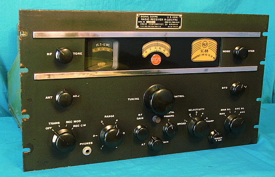
Ford VK2DRR - AR-88D, AR-88F
and AR-88LF Serial Number Log 
 

AR-88LF*

AR-88D, F

C-00660 -
C-02140 - CAN
C-02328 - USA
C-02739 - CAN
C-03786 - CAN
C-03870 - UK
C-04042 - UK
C-05102 - USA
C-05178 - USA


Alan Ford's AR-88 Serial Number Log updated:  November 15, 2010

000640 - UK
000793 - Europe
001529 - New Zealand
002385 - France
?02795 - (first digit unreadable, probably 0)
005823 - UK (scrapped)
006238 - USA
007299 - USA
007467 - UK
008421 - R1556A UK RAF mods
010396 - USA (AR-88F)
-10557*** - USA
010739 - USA
-10827*** - USA
-11308*** - R1556A UK RAF mods
-11153*** - USA
-11646*** - UK
-11791*** - USA
012628 - (AR-88F)
012700 - USA (AR88F)
014215 - USA - (highest reported serial number)
100465 - USA
100995 - USA
101032 - UK
101404 - UK


WHRM - AR-88 Series Serial Number Log
 

AR-88D (Camden): 000503 (UK), 000665 (UK), 001017 (UK),  _01529***(New Zealand), 001656 (UK), 001681 (UK), 001771 (Belgium), 001812(UK), 001982 (Australia, CL mtr), 002185 (Scot/UK), 002385 (France), 002392 (UK), _02579*** (Australia), 003039 (Australia), 003156(UK), 005055(New Zealand), 005112 (USA), 005232 (Sri Lanka), 005401 (France), 005422 (USA-parts), 005470, 005659 (USA), 005953 (UK), 006016 (USA), 007299 (USA), 007543(USA), 008911, 009351 (UK), 009591 (UK), 009566, 009653 (Australia), 009734 (UK), 009755 (UK), 010143 (UK), 010417 (UK, cab/no CL mtr), 011034(USA, no cab/no CL mtr), 011514(UK/no CL mtr, engv'd ALU panel w/ OD paint),  013809 (Brazil, cab/CL mtr), 014090(USA, cab/CL mtr), 014131(Brazil, cab, no CL mtr), 101517, 10500***(UK),11149***(Germany) 11153*** (USA), 11162*** (NZ), 11650*** (UK, engv'd panel)12083***(USA), 12331*** (USA, no cab/no CL mtr), 
AR-88D (Bloomington): 100341(Italy), 100346 (USA), 100542 (USA), 100809 (Brazil - cab/CL mtr), 101110 (UK), 101495 (UK), 101709 (UK - CL mtr),
AR-88F:   010396 (USA), 010878 (So.Africa), 010883 (USA), 011735(USA), 012396(Russia), 012410 (USA), 012637 (USA), 013879 (UK), 014037 (Belgium)
AR-88LF*: C-0294? (Czech), C-00013 (So.Africa), C-00195 (UK), C-00309 (UK), 000404?(USA), C-02140 (CAN), C-02739 (CAN), C-02785 (UK),
 C-03561 (CAN), C-03786 (CAN), C-03897 (USA), C-04399(USA), C-04689 (USA),
CR-88: 001018 (Neth), 001116 (USA), 001262 (USA), 001341 (USA), 1695 (CL Mtr, Cab/USA), C-1260 (from KPH/USA), C001899 (CAN),
CR-88A:  001268 (USA), 001316 (USA), 001923 (USA), 1518***(USA), 001700 (So.Africa), "C"001923****(USA) "C"001880****(USA),
001211 (Italy), 002926 (So.Africa),
CR-88B 209 (USA),
CR-91 (Camden):   050068 (USA), 050190 (UK), 050201 (Brazil), 050535 (UK), 050527 (UK), 050630 (France), 050728 (Italy), 050958 (Brazil)
CR-91A (Montreal): C103 (USA), C176 (CAN), C241M (USA - RCAF rcvr), C367M(CAN), C385(USA), C409 (CAN), 641 (CAN), 864 (CAN), 964 (CAN), 001281?(USA),
SC-88**:   139 (USA), 153 (USA), 181 (USA), 205?? (USA), 214 (USA), 234 (USA), 250 (USA), 255 (USA)

 For both lists: Various countries shown after the serial number indicate where the receiver is now located.

SUB NOTATIONS:

*  All AR-88LF were built in Montreal, SNs have "C" prefix and are on front panel mounted data plate.  
** All SC-88 receivers are three digit serial numbers
*** Leading Zero(s) Not Stamped in Chassis
**** "C" is later etched addition and not a factory stamping
? = Unexpected SN or format.
?? = On the SC-88 - "205" stenciled in yellow on upper right corner of panel but the actual data tag is missing, so sn:205 is an assumption.


  Operational and Modification Caveats

Here are some things to watch out for when operating an AR-88 receiver (or variant) on modern AC line voltages and for operating the receiver for extended time periods. Many of these reports come from British and European amateur users who have been operating the AR-88s on 240vac 50~ "mains" for extended periods of time in the amateur environment. Also, some of the commonly seen and unnecessary modifications that might be encountered.

1. High B+ on filter capacitors and audio output transformer when the receiver is in TRANS position - This is because the FUNCTION switch removes the B+ at the output of the triple filter of the power supply. The audio transformer is connected at the second filter capacitor/input to second choke junction and thus remains connected. Reducing the circuit load on the B+ while in "TRANS." causes the voltage to soar. Although there are bleeder resistors in the circuit their load is slight and many of these 560K IRC resistors have drifted quite high in value so they no longer perform their function as designed. Some overseas users report that the B+ excursion is high enough to cause problems in the filter capacitor unit. I tested my original CR-91 receiver and found that the B+ at the first filter capacitor was +385vdc in REC MOD and measured +450vdc in TRANS (with the AC line at 115vac and the AC tap switch set on 125vac.) This is about 150vdc of "head room" and that shouldn't cause any problems - the filter capacitor is a high-reliability, oil-filled, paper dielectric unit that's rated at 600wvdc. It might be possible that the 240vac primary tap, the highest available, doesn't provide enough "head room" when operating the AR-88 on 240vac 50~ mains. This may account for higher than normal B+ in some overseas locations where the AC Mains exceeds 240vac and could approach 250vac. RCA rated the 240vac primary to be able to go up to 260vac but, naturally, the secondary voltages will also increase, resulting in higher "no load" B+ voltages. The "normal" setting in the USA would be on the 125vac tap which provides ample "head room" for most locations. The normal encountered AC voltage in the USA is 120vac at 60hz. If the AC line is near or higher than 125vac, a line bucking transformer can be used to adjust the AC voltage as needed.

Power Transformer Failure - This seems to be mentioned once in a while on various UK sites. It's possible that while the primary winding has sufficient insulating properties at 120vac (60hz), operating the transformer primary on 240vac or higher (at 50hz) might be near the limit of the insulating properties of the primary winding. Varying the B+ load on the power transformer by using the "TRANS" position or by switching past it to turn off the receiver might have caused problems when using the highest primary voltages. Power transformer problems are seldom encountered in the USA. The following mod was fairly common in England during WWII.

Switching Transients - It's apparent that the British military believed that switching transients when actively using the "TRANS" position for receiver standby were also responsible for B+ component failures or power transformer failures. And, in fact, many of the AR-88 receivers were modified in England during WWII to avoid using the TRANS position, even if just switching past it to go to the OFF position. The mod is shown in the photo to the right. The AC power switch function is moved from the original rotary switch to the installed toggle switch. This allows the receiver to be left in REC. MOD. or REC. C.W. positions and the toggle switch allows turning off the AC line to the receiver (British "MAINS" nomenclature.) The other mod is to bring the 600Z ohm output to the LOW phones jack and the original Hi-Z jack function moved to a new jack IMPEDANCE HIGH. I haven't examined this receiver "in person" so I'm assuming that the Hi-Z jack functions as the original did with the 'phones inserted halfway allowing phones and loudspeaker and phones inserted all the way in giving just the Hi-Z phone output and placing a 5 ohm load on the loudspeaker output. If your AR-88 has an original British installation like the one shown, I wouldn't change it. It's a genuine WWII mod. Also, note in the B&W header photo for Part 1 that shows the female intercept op,...her AR-88 receiver has this very same mod.

All of the above being said, it's probably a good idea to avoid using the "TRANS" position actively as the SEND/REC function. Safe operation of the AR-88 in the sense that the British AC power mod intended can easily be accomplished by using an external power strip with its own AC power switch. If you're a worrier then using an autotransformer (Variac or Powerstat) would allow for "soft-starting" the receiver and for "soft-off" power removal. Again, most of the power transformer and B+ issues are when the receiver is operating on 240vac 50hz mains,...operation in the USA on 120vac 60hz is usually trouble-free.

See "An Easy Reversible Muting Mod for the AR-88" in Part 4. This easy mod allows T-R operation without using the "TRANS" switch.


WWII British "MAINS ON-OFF" modification

2. Audio Output Transformer failure when using speakers other than the original 2.5 Z ohm speaker - This is nonsense. An important part of the impedance calculation involves frequency. So what frequency is standard for speaker calculations? Well, actually the typical specification of a nominal impedance for a loudspeaker is the "lowest impedance that the speaker-voice coil load would present in its normal operation over its typical frequency range." Pretty vague? Most lab-quality Z-bridge analyzers use a 1000hz oscillator for Z measurements but some impedance specs might reference 400hz or 600hz. Suffice it to say that the speaker impedance is "nominal impedance" and not a "fixed value" of load on the circuit. All of that being said, the manual specifies 2.5 to 3.2 Z ohms as the desired speaker nominal impedance (the MI-8303D loudspeaker for the AR-88 showed the voice coil rated at 2.2 Z ohms at 400hz.) Note that when operating on Hi-Z earphones the phone jack connects a 5 ohm 4 watt wire wound resistor as a load across the 2.5 ohm winding of the audio transformer. Apparently RCA thought that 5 DC ohms was a close enough match to protect the AF transformer. Using a 4.0 Z ohm speaker is perfectly safe. If you can find a 3.2 Z ohm speaker (fairly easy) you will find that the AF gain control doesn't have to be advanced quite as much as with higher Z speakers. Although I have operated AR-88 receivers with 8 ohm Z speakers and haven't had any trouble, I think the 3.2Z speakers sound best with the receivers and are worth looking for (and the 4.0Z speakers sound just a good and are much easier to find.)

One thing that is important relates to receiver operation exclusively on Hi-Z headphones (with no loudspeaker connected,) in which case the operator must be sure that the 'phones are plugged into the PHONES jack "all the way" so that it operates just on headphone tap winding of the audio transformer. This is a two-position jack and when the 'phone plug is "all the way" in, then the 5 ohm resistive load is across the 2.5 Z ohm output and the phones operate on their tapped winding. Half-way in was to allow the Hi-Z  'phones to operate in parallel with the 2.5 Z ohm speaker winding to allow both speaker and 'phone operation simultaneously. NOTE: The first 3000 or so AR-88LF receivers have a different audio output transformer that has a single tapped secondary with 2.5 Z and 20 Z ohm outputs. Another note,...the 600Z output is a separate winding on the audio transformer and virtually nobody ever installs a 600 ohm resistor as a load if the output is not used,...apparently no problems result but it would be easy enough to install a 680 ohm 1/2W CC resistor,...just in case. And another note,...if you want to use just the 600Z output to drive a transformer matched loudspeaker be sure to load the 2.5Z terminals with a 4.7 ohm 2W CC resistor OR you can plug in a "dummy" phone plug all the way into the PHONES jack to operate the switch that connects the internal 5 ohm load resistor. This load on the 2.5Z winding will help to improve the 600Z quality even though it's a completely independent winding in the audio output transformer.

3. Audio Output Fixed Bias Operation - The cathode of the 6K6 AF Output tube is tied directly to chassis and the grid is biased negatively by a voltage divider operating from the negative voltage developed by elevating the CT of the B+ winding of the power transformer with resistors. Fixed bias allows the AR-88's 6K6 to develop more power with better audio characteristics with less distortion. The other option would have been self-biasing which uses a cathode resistor to elevate the cathode above chassis and therefore have the grid operate negative when compared to the cathode. This was the economical way to bias an audio amplifier and the tube will develop a little less power than it would with fixed bias. However, there are dangers when operating fixed bias. If, for some reason, the bias voltage is removed, the grid will float positive and the tube will conduct heavily. This can rapidly cause damage to the tube and sometimes might damage the audio output transformer. Some AR-88 users advocate adding a 100 ohm resistor to the cathode circuit to protect the tube and transformer in case of bias voltage failure. Theoretically, bias failure is possible, BUT, the resistors used in the bias voltage dividers are high rated, wire wound resistors (except for the 15 ohm resistor that carries very little current.) Failure of this circuit is rare. However, if you are a "worrier" then add the cathode resistor. Most of the time, these types of failures came about in a military or commercial use where the receiver was left operating continuously and may not have been "looked at" or "listened to" for long periods of time. If a problem developed it might be several hours before anyone noticed and the ensuing damage could be extensive. In amateur use today, a failure would be detected almost immediately and therefore serious damage unlikely.

4. Insufficient BFO Injection - Most versions of the AR-88 rely on electrostatic coupling of the BFO into the grid circuit of the 3rd IF amplifier tube. This was accomplished by routing the unshielded IF connecting wire about halfway around the BFO tube socket and then connecting that wire to an unused pin of the BFO tube socket. Connecting the BFO to the 3rd IF (instead of the detector) adds some gain to the IF/BFO at the detector stage and greatly reduces weak signal "masking" or "pulling" in the CW mode. But, along came SSB and that required an even higher ratio of BFO injection to the signal level to allow the BFO to substitute for the signal's missing carrier and achieve decent audio reproduction. The normal ham modification approach added a capacitor (or increased the electrostatic coupling using various methods) to have more BFO injection which seemed to give better results on SSB. However, it's much easier to just turn off the AVC by switching to MAN, increase the AF gain to near maximum and the reduce the RF Gain to a level where the signal to BFO ratio is correct for good audio reproduction in SSB. This then allows the receiver to still be used for weak CW reception. However, listening to a SSB net can be a real pain because of the different signal levels require readjustment of the RF gain for each net participant. However, you can have the BFO on and the AVC on and set the RF Gain to a desired level of sensitivity and the AVC will develop bias voltage if the incoming signal is strong enough. You can't have the RF Gain at maximum though, but it can be set to the strongest SSB signal and the AVC will prevent the sensitivity level from rising above that set point if a stronger signal comes on. If you don't do CW-DX, then maybe increasing the BFO injection makes sense. Incidentally, the final versions of the AR-88 series, the CR-88 uses a fixed 2pf coupling capacitor and the SC-88 uses a fixed 10pf coupling capacitor rather than the electrostatic coupling for the BFO so there is some precedent for that method of increasing BFO injection. 

5. Remove Negative Feedback for "Audio Improvement" - This all depends on what your definition of "audio improvement" is. This originally was done by hams who wanted louder audio with more of a "communications edge" to it. Today, most vintage receiver users, especially AM hams, would find this type of audio to sound harsh and lacking in quality. The audio response was carefully designed in the AR-88 to provide relatively low distortion, reduced harmonic content and wide range reproduction for many varied applications. Using a close match to the 2.5 ohm Z audio output probably does more to improve the audio than removing the negative feedback. I have a feeling that this modification originated around the time that the receivers had aged enough when capacitor problems and resistor drift were affecting the audio output and the receiver would have benefited more from a rebuild and alignment rather than removal of the negative feedback. When the AR-88 receivers are rebuilt and correctly aligned, their audio level is very responsive and VERY LOUD. Normal position of the AF GAIN control is about 20% advanced with a 4 ohm Z speaker.

6. Reduce Value of RF Gain Control Divider to Improve Sensitivity - The RF Gain control consists of a 66K ohm potentiometer connected to the negative bias divider to provide about -27 volts to the high end of the RF Gain pot. The low end of the RF Gain pot is connected to chassis through a resistor that can be from 5.6K to 6.8K in value depending on the particular model of AR-88 receiver. The value of this resistor determined the how close to zero volts the bias could be reduced by the RF Gain control and therefore controlled the maximum sensitivity of the receiver. This resistor value was usually set to allow about -2 volts bias at the maximum setting of the RF Gain control (minimum R of the pot.) Some users feel that a bit more sensitivity can be had by lowering the value of the series R to ground and thereby reducing the minimum bias even further. Generally, most users feel that around 2.5K is a good value. This will reduce the minimum bias to about -1.8vdc which will result in a slight increase in the receiver sensitivity maximum. Before changing the value of the resistor be sure to check its actual value as it is quite possible that the resistor has drifted to some value that is much higher than the 5.6K to 6.8K called out by the receiver design. If the resistor value is within the proper range and you want to somewhat increase the maximum sensitivity, then reduce the value of the resistor to around 2.5K This is an easy mod that can be accomplished by adding a 5.1K ohm resistor in parallel to reduce the total value of the resistance down to about 2.6K. The results are somewhat subjective but its an easy mod to remove if the results are undesirable for your receiver operation and set-up.

7. Tube Substitutions - There is a subtle difference between the metal 6SA7 (used as the mixer in the AR-88) and the glass 6SA7GT tubes. Some users believe that the glass tube produces less noise. This is easy to try since it is just a "plug-in and try" experiment. I have only found this substitution in one receiver so it's not too well known, or else it doesn't really do much. Also, substitution of 6SG7W tubes for standard 6SG7 tubes was supposed to improve signal to noise ratio. Expect results from subtle to no apparent improvement at all. What does seem to be important is the quality of tubes used in the receiver. Many users report better performance with all NOS RCA tubes installed. Certainly, a complete set of NOS JAN tubes will significantly enhance the receiver's performance.

8. Miniature Tube Modifications - CQ magazine, notorious for publishing articles that advocated the wholesale destruction of radio equipment, did it again when they published the article titled "Worthwhile Improvements for that Old Receiver" by Paul H. Lee, February 1957. The article details modifications done to a CR-88A receiver that involved the replacement of most of the metal octal tubes with seven and nine pin miniatures. Most of the article details replacing the 6SG7 1st RF amplifier tube with a 6BK7A dual triode tube, claiming a reduction in front-end noise (a common claim with miniature tube substitutions.) Also, the article continues with the BFO change to a mixer tube, 6BE6, acting somewhat like a product detector. Replacement of the Mixer tube with a 6BA7 nine-pin tube (it was the Mixer tube used in the Collins 75A-4 so it had to be good, right?) Additionally, all of the remaining 6SG7 tubes were replaced with 6BA6 tubes. The article concludes with the author bragging how Venezuela was now installing CR-88As that incorporated his RF modification. The article is reminiscent of post-L.E.Geisler's Hammarlund Super-Pro "modification-destruction" articles that were also published in CQ. Nowadays, we all know that ham modifications seldom live-up to their hype. Extensive modification of vintage ham gear, in order to make its performance more "modern," seems to contradict the whole idea of collecting, restoring and operating vintage radio equipment in the first place.    


Restoration Suggestions for the AR-88 Receivers

Cosmetic Restoration

Front Panels - The front panel is a little under .250" thick copper-plated steel. The plating was to reduce the corrosion under the paint. Unless the receiver was abused, the panel usually holds up quite well. However, many AR-88s were abused and those panels aren't in good condition. Unfortunately, most AR-88 panel nomenclature is silk-screened which will make a complete re-paint impractical. Thorough cleaning with Glass Plus and a moderately stiff brush will let you know where the dirt leaves off and the paint begins. After a good cleaning, the panel can be touched up using matched Artist's Acrylic paint. Let the touch-up paint dry over-night. A final wipe down with Armor-All or Boiled Linseed Oil (not both) will make the panel look almost like new. IMPORTANT NOTE: I don't use either of these products anymore. I've found that "3 'n' 1" oil works much better and doesn't leave the panel feeling "slippery" like Armor-All does and it doesn't have the perpetually lingering odor of the Linseed Oil. Wipe on "3n1" with a oil-dampened cloth, let set for 10 minutes and then rub off with clean, dry cloth.

There are some engraved AR-88 panels that turn up from time to time. I haven't seen one up close, so I'm not sure of the quality. It appears from what has been reported so far that the early production AR-88 for export only had engraved nomenclature. Photograph of gloss black/engraved panel is in Part 1.

On the rear of the panel are eight 1/4x20 studs that are spot-welded to the panel. These are what mount the front panel to the side panels. Sometimes, with really rough treatment, one or more of these studs might break at the spot-weld. Since the panel normally can't be re-painted, the broken stud can't be spot-welded back in place. It is possible to re-mount the stud using J-B Weld. The tensile strength of cured J-B Weld is over 3000 lbs. With careful preparation of the surfaces and by drilling a small hole in the back of the stud for the J-B Weld to bond to, it is possible to end up with a bond that is nearly as strong as the original spot weld was. When tightening the nut back onto the stud be sure to only tighten enough to compress the lock washer. Though the pull of the nut doesn't work against the J-B Weld joint the torque or twisting action does. Compressing the lock washer provides ample tightness.

RCA "Meatball" Emblem - These metal emblems seem to really react badly to moderately harsh environments. While the receiver can look pretty good, the RCA emblem will be rusty and pitted. A lot of restorers think the emblem is chrome plated but it isn't - it's the same material all the way through. Therefore, it's pretty easy to correct the damage that the rust has done. First, you should remove the front panel. This allows easy access to the emblem when the logging dial index is removed. To remove the emblem from the plastic dial cover panel note that there are two thin metal tangs are bent over to secure the emblem to the dial cover. Unbend these carefully just far enough to remove the emblem - you don't want to break off these tangs. Next, use a pair of vise grips to gently hold onto the emblem by gripping it by the tangs. It isn't necessary to grip the tangs hard - just enough to hold the emblem with something other than your fingers. Now, using a small brass brush remove as much rust as you can. Next, using a small flat Swiss "Jeweler's" file go over all of the rim area to remove any pitting from the rust. You might also have to file the RCA letters depending on how serious the corrosion is. The thing to remember is that the emblem is the same material all the way through so filing to remove the pitting won't damage the base material. Once the pitting is removed (or mostly removed in serious cases,) you can start to polish using 600 grit aluminum oxide paper. Use the 600 grit paper until the emblem is smooth and fairly polished. Next, use Semichrome or Wenol's to polish the emblem to a high shine. Remove from the vise-grips and the emblem will look like new. Normally, the red background paint comes through this process unscathed. However, if the paint is poor it can easily be removed with paint remover.  >>>

>>>    Then repaint in the background with gloss red paint. Wipe off the excess and you don't have to be very careful here. After the paint has dried, polish the front of the emblem using a cloth-covered flat surface and Semichrome or Wenol's. This will remove the remaining excess paint perfectly to expose the RCA logo just right. The whole emblem will look like new. Remount to the plastic dial cover panel and carefully bend the tangs to secure. Remount the logging dial index and then remount the front panel.

Plastic Panel Dial Cover - The plastic panel dial cover is actually a series of paint layers applied from the back via a silk-screening process. Black is applied first, then white and finally the yellowish-greenish protective layer. The black is well protected but the white sometimes seems to have damage occur to it. Usually, the white can be reapplied as Artist's Acrylic paint matched to the white/gray/beige color and thinned appropriately. Mask off the area if the white is damaged around the band indicators. This has to be very straight and masking is the only way to have it look correct. Be sure the paint is really thin so that you won't see an edge on the band indicators. You will have to apply about three coats allowing for drying time between coats. The decorative white lines around the logging scale window and the ID plate window can be applied by hand. Finish by over-coating the touch-up with a yellowish-green mix of Artist's Acrylic to protect the white. The plastic panel dial cover should end up looking absolutely original from the front and, depending on your abilities, stock from the back.

Dials - The main tuning dial, the logging dial and the ID plate on nearly all AR-88 receivers are all made out of the old type of yellowish plastic that is very photo-sensitive. The dials and ID plate will darken considerably with long term exposure to bright light (very common with the rack mount versions that are no longer in a rack.) You can clean the dials but don't use any harsh chemicals like Windex or any kind of solvents. I use "foaming plastic cleaner" that is designed specifically for cleaning plastic. Wet a cotton cloth with the foam cleaner - don't ever use paper towels on plastic dials. Make sure the cloth is damp but not dripping wet. Rub the dial gently with the cloth. Only the dirt and oxidation will come off. Be gentle - don't scrub. Always watch the lettering for any indication of thinning - the AR-88 dials are pretty tough but be careful anyway. With foaming plastic cleaner and a cotton cloth that is "just damp" no damage to the dial lettering will occur. Clean the back of the dials to enhance their illumination. That's about all you can do to the dials without damaging them. It is impossible to remove the photo-sensitive discoloration because it is deep into the plastic.

Knobs - Knobs can be cleaned by soaking in a dish washing soap and hot water solution for 30 minutes. Then scrub the knobs with a tooth brush to clean. Sometimes the knobs are scarred from rough handling with deep scratches or small chips. The knobs are made of solid bakelite and can be reconditioned by installing the knob onto a .25" diameter shaft about 3" long. This can be chucked-up in a drill press or lathe. Turn the knob and by using a file remove material where the deep scratches are. This is followed by 600 grid aluminum oxide paper or 0000 steel wool. This can only be done on the front curved surface of the knob - not on the edge or flutes. Now, remove the knob from the drill press or lathe and hand polish the knob using Semichrome or Wenol's. Because of the index pointer you can't "turn polish" the entire knob - it must be done by hand. The knob index line can be filled if necessary with Artist's Acrylic paint mixed to a "manila beige" color. Plain white will look way too bright.

Electro-mechanical Restoration

If your AR-88 Series receiver doesn't seem to have superior sensitivity and stability (far above the typical 1940s design) then it probably needs to be rebuilt. If your power supply filter chokes run hot then you have some bypass capacitors that are "leaky." Although these bypass capacitors are oil-filled paper dielectric multi-capacitor tubs and should be extremely reliable, it's very common to find that the seals have deteriorated over the years and the oil has leaked out which seriously compromises the capacitor performance and reliability. Most lack-luster performance reviews of the AR-88 series receiver can be traced to operation of the receiver with 75+ year old capacitors and resistors along with no recent check on the IF/RF alignment. A full electronic rebuild followed by a full IF/RF alignment is a common requirement for the AR-88 series receivers to function at their design level of performance.

NOTE: Although I cover one method of disassembling the tub capacitors, I don't do it that way anymore. Since PCB-type oil is involved, I've kept this part of the write-up intact but I have further notes on the current process I use for tub capacitor rebuilding.

Rebuilding the Capacitors - All of the filter and bypass capacitors in the AR-88 receivers are extremely high quality, oil filled units that rarely fail - this includes the filter capacitors. All of the metal tub capacitors are triple-capacitor units that are bolted to the inside walls of the chassis. It is very easy to check these capacitors for leakage current. Most, if not all, will be found to be useable but if you feel uncomfortable operating equipment on 75+ year old components - and you probably should - then rebuild the tubs. Top performance will require that the majority of capacitors be rebuilt or replaced. Additionally, sometimes another type of leakage is encountered - actual weeping of the oil from inside the tub. This usually is very minor leakage but besides the mess the leaking oil causes other issues with the tub capacitors.

One should remember when rebuilding the tub capacitors that up until around 1977, all oil used in oil-filled capacitors was made from Polychlorinated Biphenyl, usually referred to as PCB. These oils were complex chemical structures that had multitudes of variations, some of which were extremely toxic. Large scale, commercial chemical dumping over years created many environmental problems that ultimately were harmful to wildlife and, to a certain extent, humans. Long-term exposure to PCBs can cause skin and liver problems since the skin readily absorbs PCB oils. Common latex gloves do not provide a barrier against PCBs and protection is only afforded by a few types of rubber gloves, e.g., Butyl, Nitrile or Neoprene.

Rebuilding the capacitor tubs is a messy, smelly, laborious process. Unless you are a zealot for originality it might be better to just replace the tub capacitors with individual replacement capacitors mounted on tie strips. However, here's the process I use for rebuilding tubs - remember, you're dealing with PCB oil, so proceed at your own risk.

The tub capacitors need to have the bottom plate removed so that new capacitors can be installed into the can. Removing the bottom plate requires an old-time large soldering iron with a one inch tip. These old behemoth soldering irons provide tremendous amounts of heat to melt the solder and remove the bottom plates. This work must be done outside with lots of ventilation as the residual oil vaporizes with the heat. I also advise wearing nitrile or neoprene gloves when disassembling these types of oil-filled capacitors. You should assume that the oil contains PCBs. You must drill a couple of holes in the bottom plate before hand and let the oil drain out. The holes will also allow a way to grab the bottom plate for removal. The tub should be held in a vise and then the iron applied to the bottom and to one side. Let the iron continue to heat up the entire bottom although the solder will only become molten on one side near the iron. After about a half-minute insert a screwdriver into one of the holes and pry the bottom cover up on that side. Then move the iron to the other side of the bottom plate to keep it hot. Use a pair of heavy-duty needle nose pliers and "roll up" the bottom plate and it should come right out of the tub. Once the bottom is off, you'll have to remove the old capacitors and then wash the entire inside and outside of the can with denatured alcohol to remove the oil residue. Install the new replacement capacitors inside the tub - it isn't necessary to re-install the bottom plate (besides, it's all bent up from removal) - then re-install the rebuilt tub into the receiver chassis.   

IMPORTANT NOTE: If I were doing this today, I would use a Dremel Tool and a cut-off wheel to cut out the bottom plate at the bottom seam. Much, much faster, less smelly and less messy. First, drill a couple of holes in the bottom plate to let the oil drain out for a couple of hours and then do the cut. Four cuts are necessary to remove the bottom plate. The rest of the procedure is the same. Although it's not necessary, you can replace the bottom plate when using this Dremel Tool method since it's not destroyed in the removal process. It can be soldered back in place for the tub capacitor to look totally original (also solder the drill holes closed.) This "new" process is covered in detail with photographs in the article "Restoring the RU-16/GF-11 Receiver-Transmitter" on this website. Use Home-Index for navigating.   >>>

>>>   Though NOT recommended, the same re-stuffing can be done on the filter capacitor but it will have to be cut apart, capacitors replaced and then either soldered together or put together with epoxy and then repainted and re-installed. Be aware that the original filter capacitors have to be rated for 600 working vdc. Since the original capacitors were 4uf paper caps, use two 10uf 450wvdc electrolytic capacitors in series. This will result in a 5uf 900wvdc capacitor. To equalize the drop across the capacitors, a 1 meg ohm resistor can be connected across each 10uf electrolytic. The original oil-filled paper dielectric multi-section capacitor pack was very, very reliable. It can't dry-out unless it's leaking oil. The only reason to replace this capacitor pack IS if it's leaking oil.

All of the Micamold capacitors must be replaced since there really isn't anyway easy way to restuff them. Use SBE orange drops as replacement capacitors. The Micamolds might seem like they were high-quality capacitors but they are not "micas." They are typical paper-wax caps in a molded case - just like early versions of Sprague's "Black Beauties" with the same kind of leakage problems.  I'm working on a method to be able to successfully "restuff" Micamold capacitors and it won't be "cut the back off and leave it open" (something I saw in an ER article.)

COMPONENT QUALITY ISSUE - IMPORTANT NOTE:  Micamold capacitors are not "mica caps." They are molded paper-wax caps - an earlier version of the infamous Sprague "Black Beauty" molded capacitors. Micamolds have the same problems (maybe worse) as the typical Black Beauties with excessive leakage current. If you examine the Micamold capacitors carefully you will almost always see that the center of the capacitor body is bulging due to excessive leakage current causing heat buildup and the resulting swelling or bulge. All the Micamolds must be replaced for reliability and top performance.

When all of the bypass capacitors are rebuilt or replaced, you should note that the power transformer and the two filter chokes run significantly cooler. This is due to a reduced load that was caused by current leakage on some (most) of the bypass condensers. Additionally, alignments proceed as described in the manuals and the overall performance of the receiver is significantly improved, especially in the audio section.

Checking the Resistors - All resistors in the circuit should be checked carefully. Some of the International Resistance Corp. (IRC) resistors are prone to drift high and it isn't uncommon to find these resistors over 100% out of tolerance. It really isn't predictable which resistors will drift because sometimes you'll find the 2.2 meg resistors are fine but the 33K resistors will have drifted. Normally, higher value resistors will drift higher and low values remain stable but this doesn't seem to be the case with IRC resistors. For some reason, you'll find IRC resistors mixed with 1/2 W A-B JAN types in many AR-88s. The A-B JAN resistors seem to hold their value quite well. Top performance of your AR-88 series receiver will require careful checking and replacement of all out of tolerance resistors.

COMPONENT QUALITY ISSUE - IMPORTANT NOTE:  Intern'l Resistance Corp. resistors that were manufactured during WWII (and somewhat later) seem to be plagued with a "carbon drift" problem. Almost all IRC resistors of that period will not be at their original manufactured resistance. It isn't predictable which values will drift or by how much the resistance will change. Heat was probably the determining factor, whether the heat was from leaky bypass caps or 24-7 operation really doesn't matter since the only solution is to physically check each resistor for its present resistance value and replace any resistors that are more than 20% out of tolerance. This IRC resistance drift problem is found in every type of WWII electronic gear that used IRC resistors, not just the RCA gear. 

Cleaning and Lubricating the Gear Box - The main tuning gear box is easy to remove for a total emersion cleaning. It is mounted to the chassis with four nuts and lock washers. It is also bolted to the tuning condenser front frame with four screws and lock washers. You will also have to loosen the coupler to the tuning condenser and slide it back onto the tuning condenser shaft. You will have to dismount the front bearing support which is held to the chassis with two screws and lock washers. Then the gear box should be tipped slightly forward and removed pulling it upwards off of the chassis.

I use an ultra-sonic cleaner and use a non-flammable de-greaser to clean the gear box. The driveway degreasers work pretty well in the ultra-sonic and are easy to find anywhere. 30 minutes in the ultra-sonic and the gear box comes out looking like it is new. I then rinse the gear box in very hot water to remove stubborn grease and to rinse away the cleaning solution. Then I put the gear box under a 100W lamp for about 15 minutes to dry it out. If you don't have an ultra-sonic cleaner then you can use WD-40 in a flooding-spray along with a small long handle paint brush to clean and degrease the gears. Use lots of WD-40 (it's cheap) and the gear box should look really clean afterwards. No need to rinse in water if you use WD-40 as the cleaning solution.

It's probably a good idea to check the settings on the single ball bearings. I have found that many times these bearings are way too tight. Do one bearing at a time. Loosen the bearing lock nut and back the screw out slightly. Retighten until you just feel the bearing point contacting the ball, then tighten a bit more and then back the screw out slightly. You want just a slight pressure that holds the gear in alignment but doesn't hinder its rotation. These single ball bearings should have a drop or two of 10W oil as a lubricant.

The three ball bearings cups will need to be repacked with high quality bearing grease. You can work the grease into the bearing with your fingers and with a plastic screwdriver acting like a spatula. The bearing cup is full when you see grease emerging out the other side around the shaft. On the bearing that is for the tuning condenser shaft you will need to work the grease in from the shaft side. This has to be done with your fingers surrounding the shaft to push the grease into the bearing cup. It is more time consuming to do this bearing but it does need to be repacked for noiseless and smooth operation. Re-install the gear box and adjust the tuning shaft bearing that is in front of the flywheel weight for best action. When finished the tuning will be very smooth and light. There is a spray can that contains heavy oil available at Farm Implement-types of businesses. The oil is dark, almost black, and sprays into the bearings at room temperature. After it is sprayed, it sets up in a few minutes into a light-weight grease. Very handy for the hard to access type bearings. Kinda messy but works fine.

RCA Cabinet - Rack Mount Slot Covers - If you happen to run across an original RCA AR-88 cabinet, it might be missing these two pieces. They are the Rack Mount Slot Covers and their purpose is to trim the edges of the front panel. If these pieces are missing they are easy to replicate. They are made out of thin steel and bent on two sides only. Be aware there is a right side and a left side. Two holes allow for 12x24 round head machine screws to be used to mount the trim pieces and the receiver panel to the cabinet. Trim pieces are painted the same color as the cabinet. Outside dimensions* are:

Length* = 10.532"    Width* = 0.872"    Height* = 0.282"

Nearest Hole Center from Upper Bent Side, distance* = 1.50"

Farthest Hole Center from Upper Bent Side, distance* =  9.0"

Hole Diameter =  0.282"       Material = 20 ga. steel (.037")

* "Outside Dimension" includes the thickness of the bent side

NOTE: If you don't have access to a break to bend the sheet metal, it is possible to use 1" x 1" aluminum 90º angle to make something similar. The 1" x 1" aluminum angle is easily available at almost any hardware store. Use the basic measurements provided to fabricate and paint appropriately.


photo above: The Rack Mount Slot Covers for the original RCA AR-88 Series cabinet shown with the 12x24 round head machine screws for mounting
 

photo right: The right side slot cover showing how it is mounted

CONTINUE TO PART 3


AR-88 Part 1                            AR-88 Part 4                           Home/Index


Radio Boulevard
Western Historic Radio Museum

 Vintage Radio Communication Equipment Rebuilding & Restoration Articles,

 Vintage Radio History and WHRM Radio Photo Galleries

1909 - 1969

- 60 years of Radio Technology -


This website created and maintained by: Henry Rogers - Radio Boulevard, Western Historic Radio Museum © 1997/2023