|
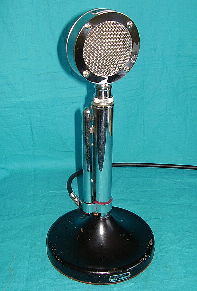
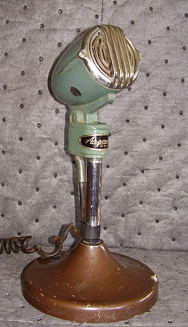
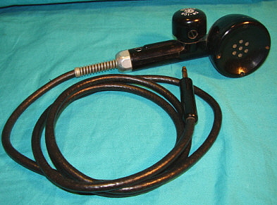
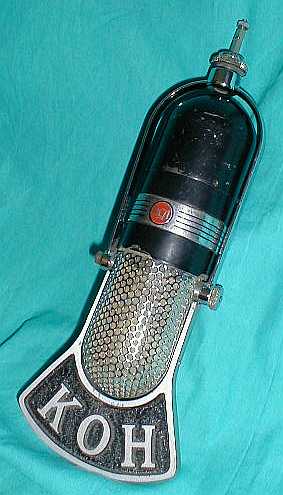
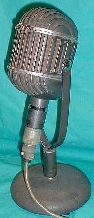
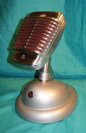
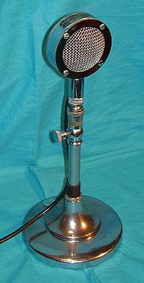
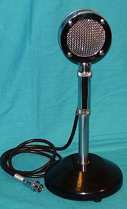
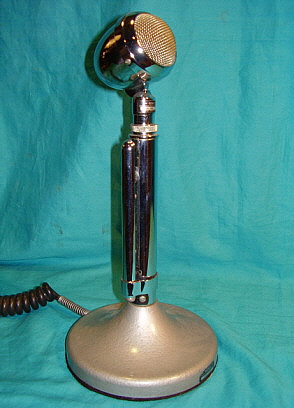
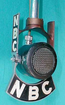
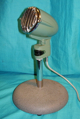
photo above: This is an "all pre-WWII" D-104 mike.
The D-104 mike head has the metal tag with Astatic Microphone Laboratory and
Youngstown, Ohio. This is the thin case version that was introduced in
April 1937. The G Stand base also has a
metal tag with Astatic Microphone Laboratory, Youngstown, Ohio. The base is painted "telephone" black
which was standard for pre-WWII G
stands. Note the dark red felt pad for the sliding grip-bar holder.
Later stands used black felt initially and then no felt at all. Also
note that the bottom cover has brown felt similar to the brown felt used
on telephone equipment. Later stands had black felt on the base bottom
cover. |
Astatic
Microphone Laboratory, Inc., aka: The Astatic Corp.
The
G
Stand (also UG, TUG & TUP)
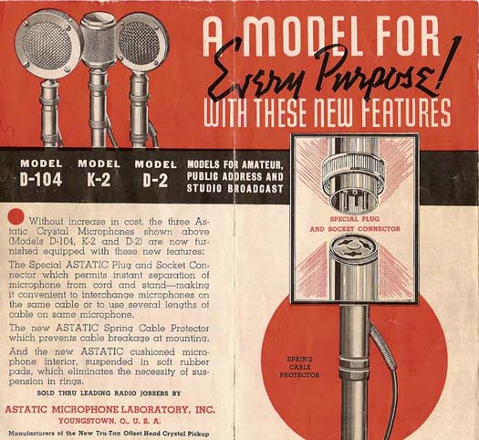
The G Stand was introduced in January of 1938. The first
QST advertisement states that the grip switch only connects and
disconnects the microphone. By March 1938, the G Stand ad states that
remote relay control is now also a function of the G Stand. The "G" came
from "grip-to-talk" as the first few ads referred to the G Stand.
In 1938, virtually all
ham transmitters were "homebrew." The majority of hams, including the
few hams that operated Phone, were generally using separate transmit and
receive antennae. This greatly simplified the Transmit-Receive operation
and only required putting the receiver into a standby condition when
transmitting. This could be accomplished by using the receiver's front
panel standby switch but many receivers also had remote standby circuits
that could be actuated by a transmitter's T-R relay. The G Stand could
operate the T-R switch which could provide many functions
simultaneously. Since the transmitters were all homebrew,
the builder decided how he would interface the G Stand to the T-R
operation of his
station.
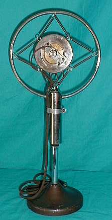
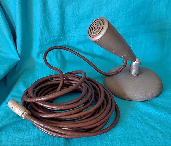
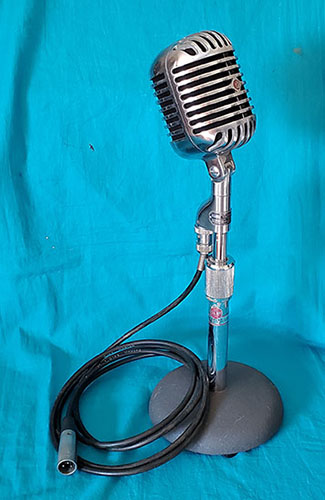
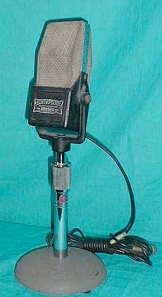
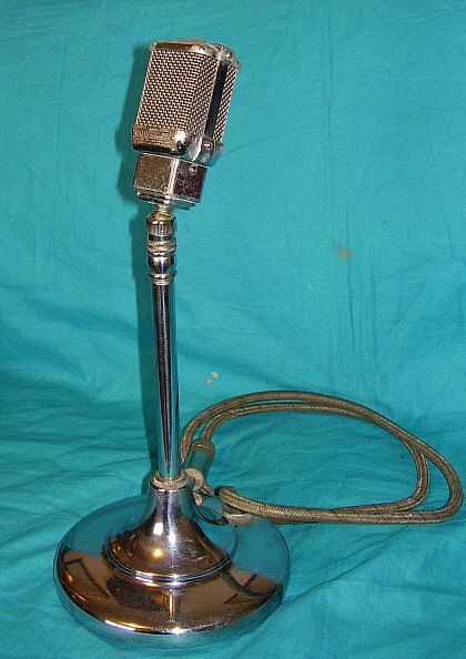
Although Astatic ads aren't specific, it's likely that
the very first G Stand cable was a single-conductor cable with shield
until the remote relay control was added a few months later. Then the
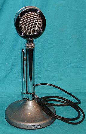
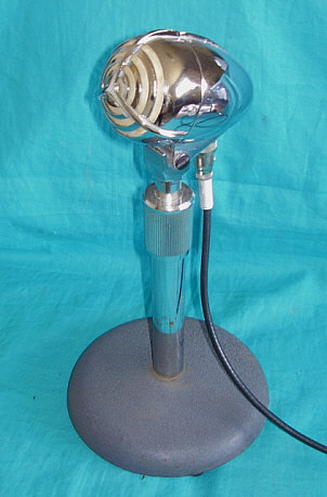
standard cable became a two-conductor shielded cable. The G Stand shown in the
photo to the left is an example of the D-104 head mounted on the G
Stand, both from about 1940. Astatic called the paint used on the base
"Telephone Black." Both the mike and the stand have metal Astatic
Microphone Laboratory - Youngstown, Ohio tags.
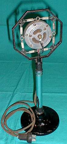
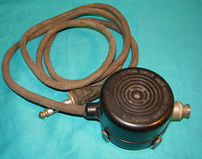
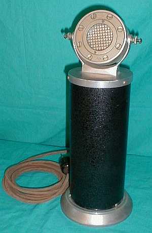
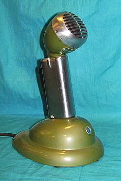
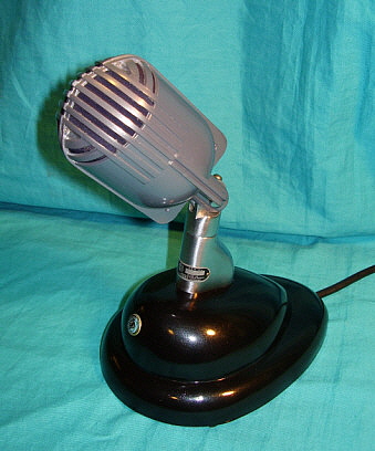
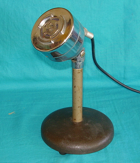
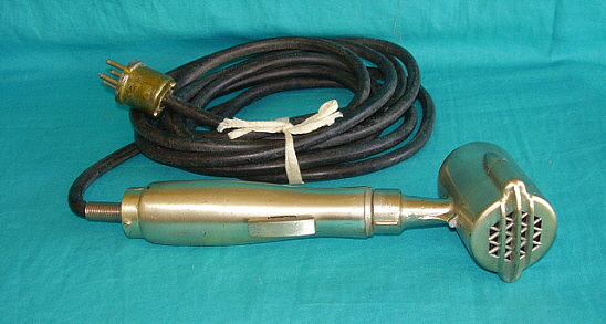
During WWII, Astatic made a G Stand with two cables, one shielded mike cable and
one two conductor rubber jacketed cable. Inside the base were two clamps
to secure the cables. The exit hole was oblong to accommodate the two
cables. Whether this
"dual cable" G Stand is standard for WWII, or an anomaly, or
if it was an option from Astatic is unknown. Bases were painted gray
wrinkle during WWII. After WWII, the base paint was changed to a silver
hammertone paint which became the standard base color after that.
|
By the 1950s, several commercially-built transmitters were
available to hams that provided PTT via a two-pin Amphenol mike
connection. This was when the G Stand began to increase in popularity
with the hams. Sometime in the late-forties or early-fifties the stand became the
"UG" and the wiring changed to allow the switch to provide more
functions. The UG indicated "universal grip" meaning the PTT line was
adaptable to various types of T-R control circuits. Usually both NO and
NC contacts were provided. The cable then became three conductor
shielded.
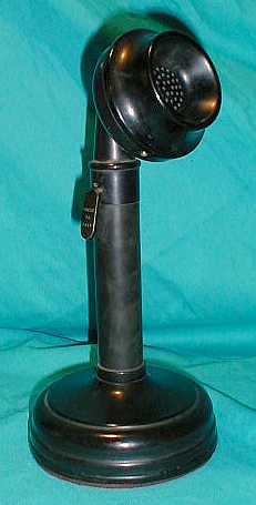
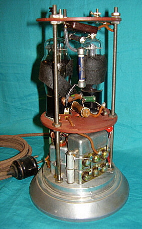
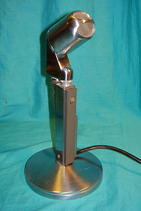
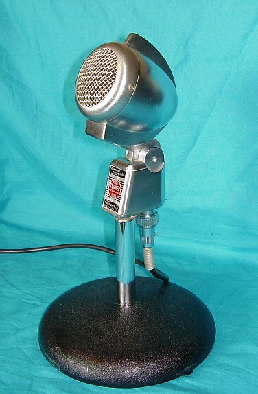
In the 1960s, a transistor amplifier was added inside
the base. This amp ran on a 9vdc battery. The stand was then designated
as the TUG with the "T" indicating "transistor amplifier." The TUG remained basically the same throughout the rest
of its production. TUG-8 is the most commonly seen version. There was
also a TUG-9 with a slightly different amplifier board. Astatic did offer a TUP stand that used a
base-mounted "push" bar. There were also a few special issue mikes and
stands that had special finishes. |
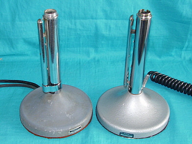
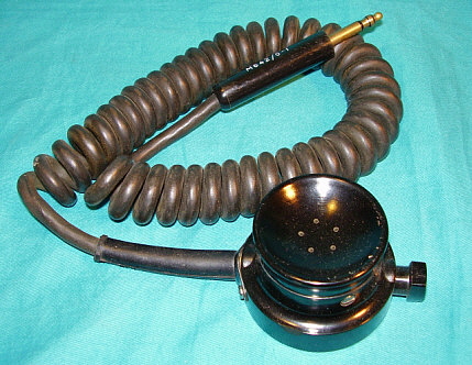
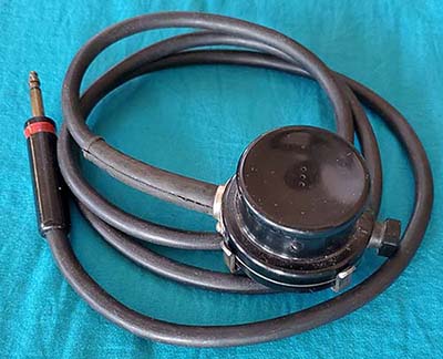
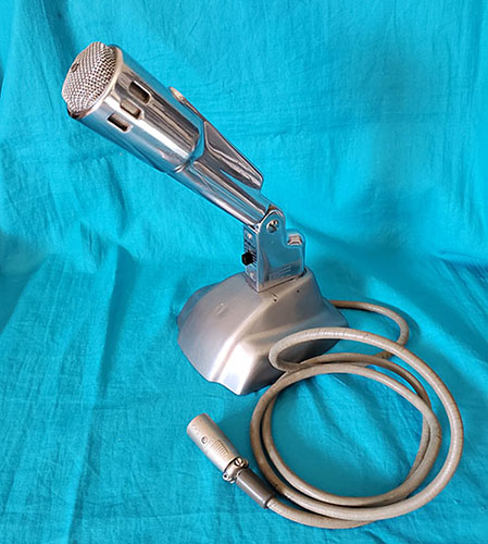
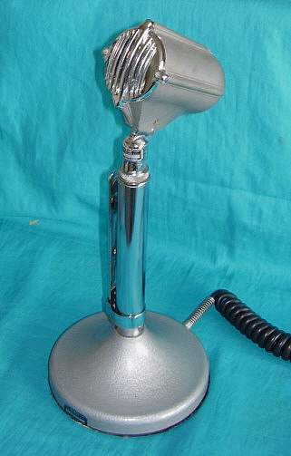
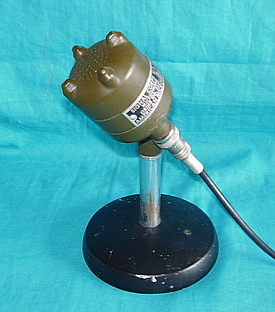
photo above: WWII two cable G Stand with gray wrinkle
base on the left. Typical TUG-8 on the right.
|
|
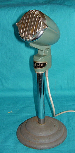 Shield M105