Radio
Boulevard
Western Historic Radio
Museum
Collins Radio Company
32V Series
Medium Power Ham Band Transmitters from 1946 - 1954
includes 32V-1, 32V-2 & 32V-3
by: Henry Rogers
WA7YBS
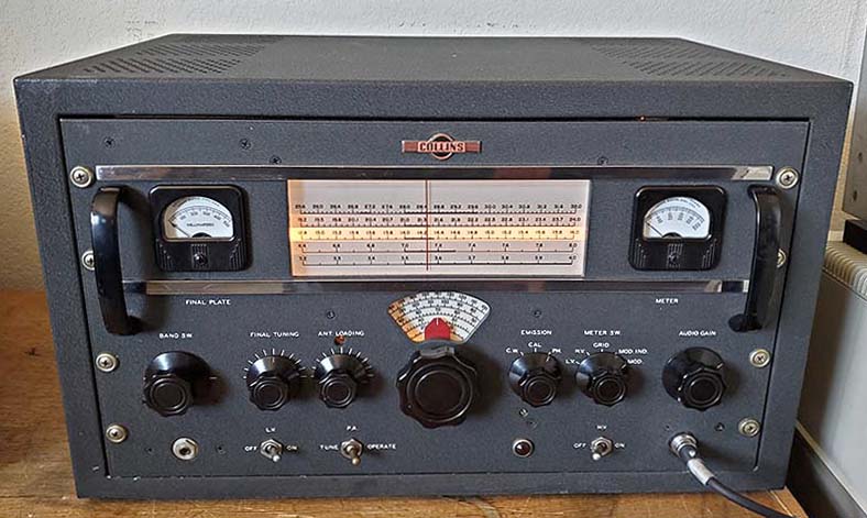
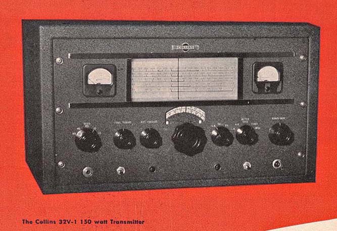
1946 32V-1 Artwork from 1947 Ad in ARRL HB
|
Radio
Boulevard
Collins Radio Company 32V Series Medium Power Ham Band Transmitters from 1946 - 1954 includes 32V-1, 32V-2 & 32V-3
|
|
| During WWII, Collins Radio Company developed several transmitter design specialties such as motor-driven auto-tuning, improved permeability tuning, tuned frequency multipliers and other sophisticated electro-mechanical approaches to transmitter operation, many of which Collins incorporated into their commercial transmitter designs (as described in their advertisement in the 1946 ARRL Handbook.) A few of these specialties were worked into the design of Collins' new, mid-power, amateur transmitter, the 32V-1. Introduced in late-1946, the 32V Series evolved into three distinct versions, the last of which was produced up into 1954. While the 32V transmitters were certainly well-built pieces of equipment, they do have their operational idiosyncrasies and the complex mechanical design along with the dense component layouts can frustrate any restoration project. The following write-up should give prospective purchasers and current owners some of the insight into the ownership, rebuilding and operation of each version of Collins' post-WWII medium-power transmitters. |
|
Collins Radio Co. - 32V Series Transmitters |
|
32V-1 1946 to 1948 - Initial Model with an Oddity |
|
|
The 32V-1 transmitter was introduced in late-1946. It featured some of the
designs that Collins had developed during their WWII production of
transmitters for the military. In a 1946 ad, Collins showed how their
WWII designs had been implemented into their commercial transmitters and
a small inset mentioned how some of these same designs were going to be
used in their new amateur transmitter. When first introduced, the 32V-1
transmitter's design was more advanced than any other commercially-built
amateur transmitter available. It used a
Permeability Tuned Oscillator, a PTO, as the VFO-Master Oscillator along
with three tuned-multiplier stages to
create a tracking exciter that allowed the transmitter to stay "in tune"
as the frequency dial was changed. All that was required of the operator was
to set the frequency and then "match" the transmitter output to the
antenna impedance. Other than the Pi-network, all circuits were
automatically tuned as the frequency dial was
adjusted. Collins used their
coil-slug rack carriers in the frequency multiplier section and full permeability tuning
was used throughout the oscillator and
multiplier stages. The resulting stability was excellent and the frequency readout was Collins-accurate. The CW mode keyed the transmitter stages using blocked-grid keying with -75vdc as the negative bias supply. The Phone mode used a 6SL7 dual triodes in series and a 6SN7 dual triodes in parallel to drive the pair of 807 modulator tubes. The audio response was 200hz to 3000hz. The PA tube was a Raytheon 4D32. The 32V Series allowed selectable +HV voltage - either +600 or +700vdc - the lower voltage allowed the 4D32 to run at the manufacturer's specifications for continuous duty and also allowed for reduced output power for driving other devices. The +700 switch position selected a tap on the HV transformer primary that increased the turns ratio for the higher secondary voltage. The +600 switch position selected the full number of primary turns thus reducing the ratio and the secondary voltage. The 32V-1 power input was rated at 150W CW and 120W Phone. The power output on AM phone is generally about 110 watts if +700vdc plate voltage is used and about 75 watts output if +600vdc plate voltage is used. This assumes a good condition 4D32 and good condition 5R4G tubes. Output is less on 15M and 10M. |
| If the +600vdc plate voltage is used, then the Modulator bias
(chassis mounted pot adjustment) would have to be set lower to 50mA
and the transmitter would be loaded to around 180mA of plate
current. On +700vdc plate voltage, plate current on AM phone would
be loaded to 225mA and Modulator bias set to 55mA. A 600Z ohm tap on
the modulation transformer provided 60 watts of audio available to
drive external loads. The +HV power supply is a choke input filtered, +700vdc using two 5R4G rectifier tubes. The tapped primary on the +HV transformer produced the optional +600vdc that was selected by a toggle switch located on the rear chassis panel. The +LV used a 5Z4 rectifier and used an input choke and a smoothing choke with 4uf 600vdc oil filled paper dielectric filter capacitors in the filter. The +HV used two 4uf 1000vdc oil-filled paper-dielectric capacitors connected in parallel for its filter. |
 |
A 6SL7 acted as the sidetone oscillator
with the tone adjusted by a control located on the chassis under
the lid. The volume of the sidetone oscillator was controlled by the
AUDIO GAIN control when in the CW mode. The reproducer for the
sidetone should have an impedance around 600 ohms. For Phone operation
Push-to-Talk was available by grounding pin 2 of the Amphenol
Two-pin microphone connector. Actually, pin 2 has a relatively high
voltage riding on it if it isn't grounded since the voltage to power
the auxiliary relay is from the +LV supply through a divider network
which reduces the voltage on pin 2 to about +100vdc. The right side meter was a
"multi-meter" that could read +HV, +LV voltages, GRID drive level at
the PA, MOD was the modulator plate current and MOD IND was an
indicator of the relative modulation level. The left side meter was the
FINAL PLATE current. The rear terminal strip had connections for driving a send-receive relay, remote standby for the station receiver, muting if a Collins 75A-1 receiver was being used, remote actuation of the PTT, along with other connections to allow the interfacing of the 32V-1 with other station equipment. The antenna and ground connections are push-terminals. The transmitter weights just over 100 lbs in the cabinet and about 80 lbs out of the cabinet.
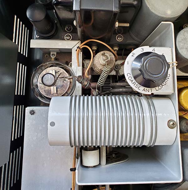
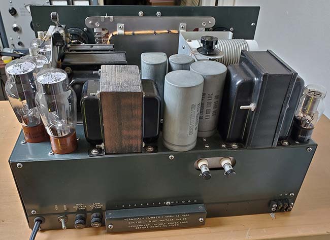
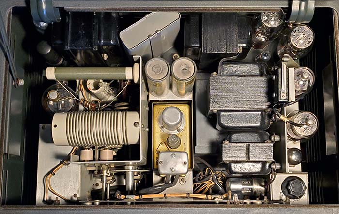
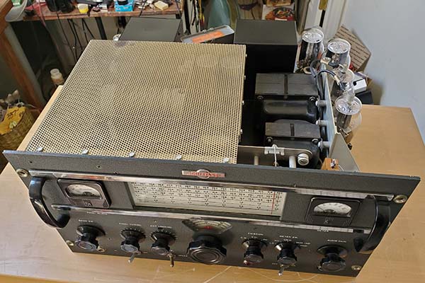
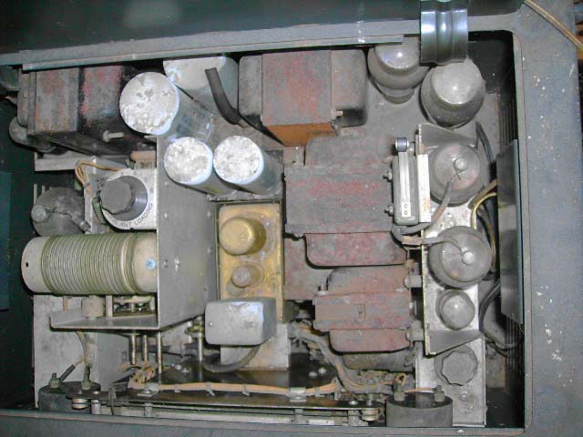
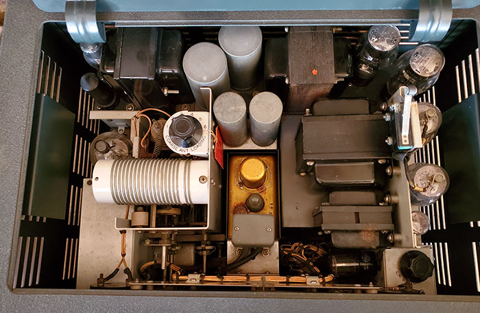
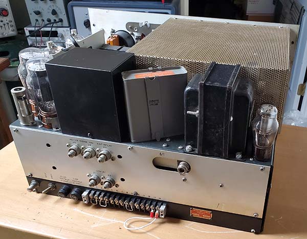
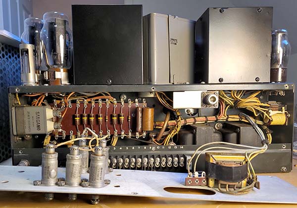
photo left: Top of the 32V-1 chassis showing the dense component layout of the design. Note the "under-the lid" location of the COARSE ANT LOADING control, a six-position switch that selects different fixed-value capacitors for the Pi-network. The two large can capacitors are 4uf 1KV caps connected in parallel and the smaller cans are the 4uf 600vdc caps (part of the dual section filter for the LV.) Lower right is the CW OSC TONE control - the AUDIO GAIN controls the sidetone volume. The micro-switch by the 807 modulator tubes is the lid interlock switch. Note the lack of two 0A2 regulator tubes next to the two 5R4G rectifiers (upper right corner.) This indicates that this 32V-1 is an early model (within the first ~500 transmitters built.) |
Oddity?
- The 32V-1's "oddity" is certainly the "under the
lid" location for the COARSE ANT LOADING control. If
the owner-operator intended to utilize more than one band or to QSY
from CW to Phone on a specific band then complete access for opening
the lid had to be provided. With a non-reactive 50Z ohm antenna load
the front panel ANT LOADING becomes a very fine adjustment, at least
on 80M, 40M and 20M. >>>
|
>>> Another oddity is the lack of a "TUNE" mode for the 32V-1
which requires the user, when tuning the transmitter - especially into
an unknown load - the reduce the COARSE ANT LOADING control to 1.
Then the FINAL TUNING set to
resonance ("dip the plate") and from there, the COARSE ANT LOADING
can be increased incrementally as needed. Each adjustment will require lifting the
lid, which actuates the lid interlock turning off the +HV so that the
COARSE ANT LOADING can be safely adjusted. Once the change is made
the lid is lowered and the transmitter keyed and the PA tuned. This is repeated
until the plate current indicates the Pi-network Coarse Load is adjusted
to the range that allows using the front panel ANT LOAD to
closely match the antenna load and have the transmitter at full output power. If the 32V-1 owner/operator liked to change
bands, modes or antennas frequently, this "lifting the lid" tuning
procedure must have seemed very inconvenient and overly awkward.
|
| Late-version 32V-1
- Late version transmitters will have two 0A2 regulator
tubes mounted next to the 5R4G rectifiers that act as screen voltage
limiters. There are at least two different editions of the
32V-1 manual, the later version has the updated schematic
showing the 0A2 tubes. The 32V-1 was produced from late-1946 through mid-1948, or just under two years of production. The 32V-1 transmitter isn't found too often today. Most examples found nowadays will have some past modifications installed where a former owner was trying to alleviate TVI issues. Many 32V Series transmitters were later abused in various ways when the transmitters lost their value and were then used on 11 meters by illegal Citizen's Band operators (illegal because the FCC regulations limited maximum power output to 5 watts and limited the maximum distance of communications to 25 miles.) Early Television Sets and TVI - The effects of harmonic radiation from ham transmitters on television reception was certainly not in the forefront of design in 1946. There weren't many TV sets even on the market yet. Huge sales of TV sets started in 1947 when many manufacturers, some old time companies and a lot of new TV set builders, introduced their new television receivers to an eager consumer market. Certainly by the end of the 32V-1 production in mid-1948, the TVI situation was obviously becoming a real problem for hams. Many of the TV sets used a 21mc IF strip for the video that was a harmonic for 40M operation. Many TV fans were located great distances from the nearest TV broadcast station and were trying to receive very weak TV signals over the air using folded dipole antennas with 300Z ohm open feed line. Harmonic interference from ham transmitters was rampant and TV fan's complaints never-ending. Collins introduced the 32V-2 model in mid-1948 and it featured several upgrades that tried to alleviate the increasing TVI problem. |
|
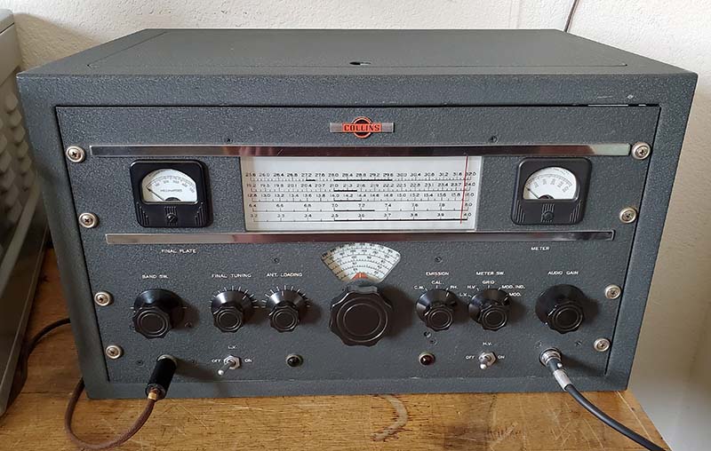
32V-2 1948 to 1952 - Upgrades with Pi-L Network Issues |
32V-2 Pi-L Network Problems: The Pi-L network used in the 32V-2 had its share of problems. So much so that Collins issued a 32V-2 Service Bulletin #1 in 1956 that described a minor modification to the location of the tap on the L-network coil (L404) for 10 meters. The upper end tap had been on turn 11 of the inductor (counting from the top of the coil) and the service bulletin indicated it should be moved to turn 8 for better tuning on 10M. The second part of the Bulletin relates how to adjust the feeders on the antenna matching device to provide a low reactance 50Z ohm load. Collins believed that the problem in the Pi-L network was due to a very high SWR encountered during tuning that then exceeded the voltage levels that the Pi-L network components were designed for. This probably was true for a lot of users that tried to "load up" just about any piece of wire they could find and didn't use Collins' antenna designs that were provided in the manual (or any known resonate, 50Z or 75Z antenna for the frequency of operation.) Certainly, adjusting the loading and tuning of the transmitter at full power also contributed to some of the Pi-L network issues. At any rate, almost any 32V-2 Pi-L network is sure to have blown at least one of the fixed-value mica capacitors sometime in its lifetime. Due to the design, the failure of the fixed-value capacitors will only occur on either 80M or 40M. The remaining bands use only the air variable C for loading. However, damage to the C-switch from arcing could occur on any band. Here are my experiences with the 32V-2 Pi-L network,...I almost always used an antenna matching coupler that allowed matching a 135' CF dipole fed with ladder line (balanced) to a 50Z unbalanced output. I always had a 1:1 match as far as the 32V-2 was concerned. However, twice I've blown one or more of the mica caps in the Pi-L network. My problem was how I was tuning up the 32V-2. At that time, I didn't use a telegraph key to tune the transmitter but instead relied on the fact that without the telegraph key being plugged in, the transmitter was always "key down." This seemed a convenient way to just leave the transmitter in the PH mode and do the tuning. This led to my laziness in leaving the 32V-2 in PA OPERATE and "touching-up" the ANT LOADING control and then not paying attention to where the knob index was which led to crossing the C-switch points with the resulting mica cap damage. The 32V-2 is subject to mica capacitor failure due to the upgrade that moved the COARSE ANT LOADING switch from a chassis mounted component accessed under the lid of the transmitter to a front panel control integrated to operate in conjunction with the ANT LOADING control. This problem only affects the 32V-2 model and is most common when a telegraph key is not installed in the key jack. The telegraph key forces the operator to hold the key down for tuning and loading functions. This usually prevents the operator from inattentively crossing the ANT LOADING C-switch points with the key down. Without the key installed in the jack, the transmitter is always "key down" and it becomes far easier to accidentally cross the C-switch points at full power in the PH (Phone-AM) mode while adjusting the ANT LOADING control.
32V-3 Corrects Problem - The "blowing caps in the Pi-L Network" was certainly an issue for Collins since they issued a service bulletin describing the problem in 1956, although this was even after production of the 32V-3 had ceased. The 32V-3 corrected this problem by connecting a pair of 2500wvdc capacitors in series for each capacitor required. That halved the capacitance value and doubled the working voltage of each pair to end up with two 220pf at 5000wvdc and one 470pf at 5000wvdc. An examination comparison of the Pi-L networks in a 32V-2 and a 32V-3 transmitters will reveal that the 32V-2 "capacitor stack" consists of just three caps while the 32V-3 has two "stacks" of three each capacitors. This Pi-L network problem was certainly the 32V-2's Achilles' Heel. The final cure might be to install the 32V-3 upgrade into the 32V-2. There is ample room in the Pi-L Network compartment although any work on the mica capacitor stack will require removing the plate choke (easy to do.) However, the original types of mica caps are almost in the "unobtainium" classification - at least in the values that are needed. Even if the 32V-3 upgrades were installed, one should still tune in the TUNE mode, use a known-Z, low reactance antenna and use a telegraph key for the tune up procedure. NOTE: The 32V-1 wasn't affected by this problem because the COARSE ANT LOADING was a separate control switch that was located under the lid of the transmitter. Lifting the lid opened the "interlock safety switch" that turned off the +HV making it was almost impossible to adjust the COARSE ANT LOADING switch with the key down and the power on (although I suppose someone could jumper the interlock switch if they wanted to defeat the obvious benefit the interlock provided.) |
|
32V-3 1952 to 1954 - Major Upgrades for the 1950's TVI Problem |
|
|
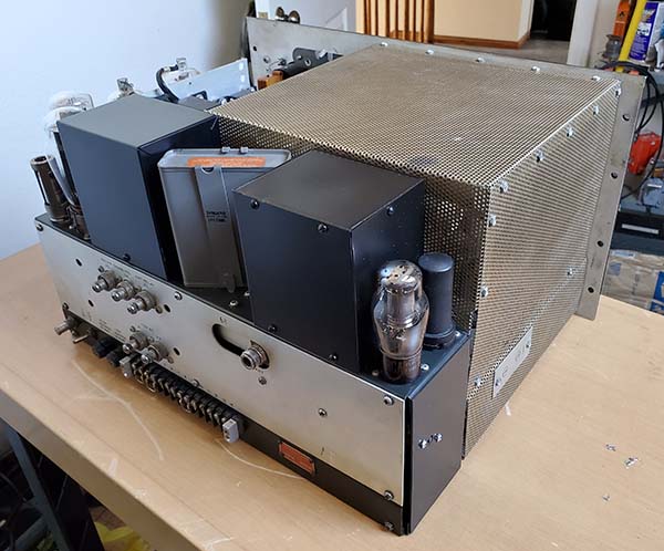
The TVI Issue - Introduced in 1952, the 32V-3 was the last of the 32V series of moderate-power, AM-CW transmitters produced by Collins. From the time that the 32V transmitters were first introduced in late-1946 up until the introduction of the 32V-3 version, television broadcasting had grown explosively. Everyone was trying to receive TV broadcasts "out of the air" via their roof-top antenna. Many of these TV-fans were in rural areas ("fringe areas" as it was called for TV reception) and "over-the-air" TV signals in those areas were very weak requiring a large TV-yagi antenna mounted on a tower in order to receive a fairly clear picture. In addition to the TV signal strength problem, many early television circuits used a 21mhz IF strip for the video. At the time of design, 15 meters wasn't an accessible ham band although it was designated to become one (in 1950.) Additionally, the 21mhz video IF was harmonically related to the 40 meter ham band. All of these potential TVI problems and their seeming insolvability seemed to restrict many hams from being able to operate in a neighborhood populated with roof-top TV antennas. As a result of this ever-increasing TVI problem, most of the commercially-built ham transmitters underwent considerable modifications in an effort to minimize harmonic radiation. Most manufacturers redesigned the mechanical housings of their transmitters providing complete RF-sealed containers that hopefully would eliminate (or at least reduce) the harmonic RF emissions. Pi-L network upgrades were incorporated to reduce harmonic emissions and 30mhz-cut-off, low pass filters were installed by most ham operators. Coaxial cables became the only accepted method to transfer RF energy from the rig to the antenna. As a result of the continuing TV-boom that had started in 1947 and was still rapidly growing in the early fifties, Collins redesigned much of the old 32V-2 mechanics and some of the circuits so that hopefully the new 32V-3 would be able to function in "TV-land" without causing interference (if the transmitter was set-up and operated correctly.) |
|
32V-3 Changes - There were a large number of changes incorporated into the 32V-3 and most (but not all) were specifically for reducing TVI. Full shielding of the PA and antenna matching network is accomplished with a two-piece, wrap-around, perf-metal shielded cage. Lots of mounting screws assures good grounding and certainly makes any routine tube checking in the PA and multiplier sections (six tubes plus two regulators) a task. The antenna matching network was extensively changed to provide a more durable and higher-Q Pi-L network that reduced the possibility of harmonics making it to the antenna. The fixed-value, individual mica capacitors with the 2500wvdc rating were changed to series pairs that increased the working voltage to 5000vdc. The cabinet was completely redesigned to be "RF-tight" by eliminating the access lid and, again, making any routine maintenance a "chassis-out-of-the-cabinet" job. Since RF harmonics had a tendency to radiate by getting into accessories, the Antenna T-R relay drive, receiver muting access and AC power inputs were all routed through capacitive bypass, feed-thru filters. Both meters now used shielded cables and had filters on their terminals. Other updates included the 70E-8B PTO change (32V-1 and V-2 used the 70E-8A, the "B" version floated the PTO tube filaments,) +LV power transformer, +HV input choke and the +HV transformer were changed to hermetically-sealed units (also found in late-production 32V-2 transmitters) and changes to the rear covers necessary because of the Antenna T-R relay power, receiver muting and AC input updates. The 32V-1 and V-2 had a built-in CW sidetone oscillator but since that required external connections to a reproducer that might contribute to harmonic radiation, the sidetone oscillator was eliminated in the 32V-3. The sidetone oscillator tube, V205 - 6SL7, was eliminated, leaving an empty tube socket mounting hole in very early 32V-3 transmitters (that's what pictured in the V-3 manual. Most production probably used new sheet metal without the V205 hole.) The changes mentioned so far were mainly for TVI reduction. A separate filament transformer for the PTO tube along with screen regulator tubes for the PTO tube were added to the 32V-3 that aren't present on the 32V-1 or V-2. However, the PTO tube filament transformer is actually connected up as a "hum bucker" by having the CT of the filament winding connected to the -75vdc bias voltage. Since the PTO tube filament is "floating" (not connected to chassis-ground) the -75vdc "swamps" the 6.3vac and it appears as DC voltage on the tube filament. This was to reduce any 60hz modulated hum on the PTO output. An additional electrolytic filter capacitor was added to the -75vdc bias voltage supply to further reduce any hum on that source of bias voltage.
|
|
|
| TVI and the 32V-3 Today - The 32V-3, the last of the 32V Series, had its ultimate mechanical and electronic design influenced by an environment that made ham radio operation almost impossible due to the public's "over-the-air" TV BC reception. This environment persisted until cable-TV came on the scene, providing TV-fans with very strong signals routed through shielded cables. Almost simultaneously with cable-TV's introduction, the popularity of SSB voice transmissions replacing AM voice also tended to greatly reduce TVI due to the lack of an AM carrier envelope that was easily rectified (detected) by just about anything related to TV reception. Much later, when HDTV moved the whole TV BC much higher in frequency, TVI became a "non-issue" - a thing of the past. Today, most vintage ham radio enthusiasts can operate either the 32V-1, 32V-2 or the 32V-3 without any TVI problems (other than perhaps fundamental overload - too much signal, too near too many TV receivers - like in an apartment building where you're running an "indoor" antenna.) So, maybe the 32V-3 can be considered a "relic from the past" that represents one of the most "difficult times" in ham radio. And, unfortunately, a time that to-this-day, has influenced how the ham radio operator is perceived and treated in his own neighborhood. |
|
Is the 32V-3 "The Best of the Lot?" |
| All of the final upgrades are in the 32V-3 but
does that mean it's the best transmitter of the 32V Series? If you're
interested in the most stable, best sounding, most reliable transmitter
of the 32V Series,...then the answer is yes. There were important
upgrades to the Pi-L network, to the voltage regulation for the PTO
screen voltage, DC voltage on the PTO tube filament,
better filtering for the bias supply. Those aren't found on the earlier
versions. But,...
If you're also interested in a transmitter that's easy to perform maintenance on,...well, hopefully the V-3's reliability will help prevent frequent disassembly. With the V-3, any checking, adjusting, minor maintenance like tube testing, all require removal of the chassis from the cabinet and many times the removal of the two perf-metal shields - lots of work that usually has the owner postponing necessary routine maintenance or any rework to the last possible moment. However, other than tube testing and shield removal, the earlier 32V versions will also require chassis removal from the cabinet for alignments, some adjustments and rework. The 32V-3 was in production from mid-1952 up into 1954, or about two years. While the 32V-3 isn't particularly rare, it certainly isn't encountered as often as the 32V-2, which is the most often found model of the 32V Series. In my opinion (and it's just that,...an opinion,) I'd rate the 32V-3 as the best operating and most reliable version of the 32V series of transmitters. The 32V-1 as the "next best" mainly because it's the initial version with all of the "interesting" quirks like the "under the lid" adjustment of the COURSE ANT LOADING that actually saves the Pi-network from damage and it still puts out a decent quality signal. Additionally, problems related to the V-1's tendency towards harmonically related TVI are a thing of the past since all television broadcasting is HDTV on much higher frequencies nowadays and most home-TV signals are routed with shielded coaxial cables and the origin is either a microwave signal from a satellite or a super-strong signal from a cable provider. Unfortunately, the upgrades to the 32V-2 caused as many problems as they tried to cure. It comes in last mainly because of the 32V-2 Pi-L network's vulnerability to damage from inattentive tuning and loading or unexpected high SWR encounters. However, on the positive side though,...V-2s are usually the most reasonably priced version and, if carefully matched to known antenna loads, will provide excellent signal quality and mostly reliable operation. |
|
32V Series Operational and Rework Caveats |
|
1. The Pi-L Network has a very high-Q so resonance is pretty sharp. Expect 10 meter resonance to be particularly sharp. Check the location of the tap on the smaller network coil (L404) for V-2 transmitters to see if it's on turn 11. It should have been moved to turn 8 if the service bulletin was ever read (SB 32V-2 #1, listed as "Filtering.") On the V-1, be sure the COARSE ANT LOAD is preset on position 6 to load on 10M. The V-1 originally came with a red paper-string tag attached to the COARSE ANT LOAD switch shaft warning the operator to only use position 6 from 26.5mc to 32mc. 2. Without a telegraph key inserted into the jack the transmitter will be always be "key down." This seems convenient if "AM-PH only" operation is of interest. Tuning up in the PH mode and in PA OPERATE can lead to accidental crossing between C-switch points using the ANT LOADING control while the transmitter is at full power. 32V-2 is the most vulnerable to damage. The use of a telegraph key, tuning up in the CW-TUNE mode and being cautious of the ANT LOADING C-switch points helps prevent damage to the Pi-L network in the V-2. 3. Audio Gain does have to be advanced pretty far if a non-amplified crystal mike is used. Expect about 50% to 75% advanced for near 100% modulation. To a certain extent it depends on the condition of the 6SL7 audio preamplifier. Try to use a NOS tube in that position. 32V transmitters have a powerful audio section that is fully capable of easily attaining full "cut-off" (what happens when the negative modulation level tries to go further than -100%.) This can damage the modulation transformer over time. Use an oscilloscope to monitor modulation levels. 4. Mechanical "buzz" when in transmit at full power with +700vdc plate voltage is caused by L-303 and also that the HV power supply filter is a choke input circuit - notorious for mechanical "buzz." Some transmitters are worse than others. Check value of C305 but it's probably okay. Usually, if the "buzz" is really annoying, a small cardboard wedge can be placed between L-303 and T-202 to reduce the vibrating and dampen the "buzz." The "buzz" is most often encountered in the 32V-3 because of the design of the fully enclosed cabinet and all of the extra shielding, screws and mounts for the shields tend to "amplify" any mechanical vibration. An easy thing to try is to loosen all eight of the front panel to cabinet mounting screws. If these screws are tight they tend to make the chassis vibration resonate more in the cabinet. Just have the front panel cabinet mounting screws barely touching the front panel. Also try lowering the input AC voltage to 115vac which reduces +HV and overall current draw which can help to reduce mechanical vibration. >>> |
>>> 5. Watch pin 2 on the Amphenol microphone connector. The voltage on this pin floats around +100vdc when PTT is not actuated. The voltage is routed through the auxiliary relay coil by grounding pin 2 with the PTT function so, when pin 2 isn't grounded, the voltage will be present on pin 2. The +100vdc is derived from +LV through a divider network so the voltage is present on pin 2 whenever the "LV" is on. Probably the safest approach is to connect up your microphone before you power-up the transmitter. Also, be sure that your mike's PTT is an actual mechanical switch contact that is rated for the voltage level and the current required to actuate the PTT relay. The Astatic TUG stands use mechanical switch contacts for PTT (as do most mikes from that time period.) 6. The 32V-1 doesn't have a SO-239 connector for the antenna connection but has two push terminal connections instead. This is not a balanced output - it is the unbalanced output from the Pi-network. Use 50Z ohm coax for the feed line from the transmitter to the antenna coupler (or direct coaxial-fed antenna.) You have to connect the shield of the coaxial cable to the "G" terminal and the center conductor to the "A" terminal. Don't worry about TVI as that's a thing of the past with modern HDTV (except for fundamental overload problems.) Don't change the original set up to install an unnecessary SO-239 coax fitting. Also, the 32V-3 uses a N-type connector for the RF output. Probably easiest to use a N-type to SO-239 UHF adapter unless you would like to try making up a coaxial cable that has an N-connector installed. 7. When planning rework, note that the 70E-8A used in the 32V-1 and V-2 is not directly interchangeable with the 70E-8B that's used in the 32V-3. The "A" version grounds one side of the PTO tube filament and operates the tube filament from the 6.3vac winding of the LV power transformer. The "B" version has "floating" tube heaters (not grounded) to allow the PTO tube to work with the separate filament transformer that's connected as a "hum-bucker." |
|
Operating the 32V on High Line AC There are many opinions about running any of the 32V Series transmitters on the modern elevated AC line voltages many of us are now provided by the local utilities. The 32V transmitters were designed for 115vac input and most home service now runs at least 120vac and most of the time even higher. The increased line voltage is usually at least 5% but still that does increase the tube heater voltage and +HV somewhat. Whether the "high line" voltage really causes any problems is most likely a subjective judgement but certainly the closer the AC line is the 125vac the more worry it will cause. An easy solution to the problem is to use a "bucking transformer" to lower the line voltage to the 32V transmitter AC input. A 6.3vac filament transformer is very easy to find and they are perfect since the resulting AC output is about 115vac (if your line is about 122vac, for instance.) If your AC line is 125vac, then two 5vac rectifier filament transformers can be used (these are a little more difficult to find.) All that's required is the appropriate filament transformer and an input and output socket to allow easy connections. Since only 6.3vac is in the AC input, the VA rating of the transformer can be relatively small. A 5A 6.3vac secondary (~600 watts at 115vac) would be more than adequate for a single transmitter. Although an autotransformer (a Variac or Powerstat) could be used, it does "tie up" a valuable and expensive piece of test equipment where the "bucking transformer" can be very inexpensive and does essentially the same thing (well, not adjustable though.) When connecting the secondary in series with the primary the "phasing" of the secondary determines if the resulting AC out "adds" or "bucks" so just reverse the secondary wires if you get an increase instead of the desired decrease in available AC voltage. Overall, the 32V transmitter does seem to operate more "to spec" when running at 115vac input and seems to mechanically "buzz" less when transmitting. The following are some "key-down" voltage comparisons: 122vac input 115vac input +HV +780vdc +715vdc +LV +240vdc +240vdc Tube Heaters 6.9vac 6.3vac Power Output 75M Phone 115 watts 115 watts Mod Idling I 55mA 25mA - the modulator idling current will have to be readjusted to 55mA with the transmitter operating on 115vac (because of the lower plate voltage.) Another quick solution would be to run the transmitter on +600vdc +HV which will probably be almost +700vdc with >120vac increased line voltage although this only affects the plate voltage on the PA and Mod tubes. The +LV (no load) and the tube heaters will still be slightly elevated in voltage. You will have to readjust the MOD idling current whenever the +HV is changed (easy on the V1 and V2, a PIA on the V3.) |
|
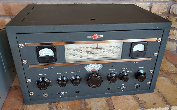
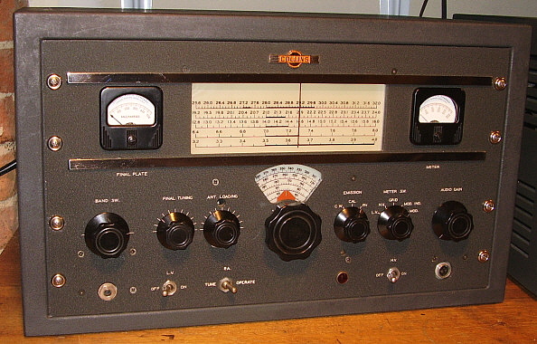
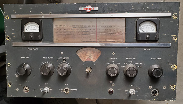
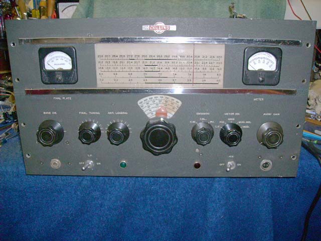
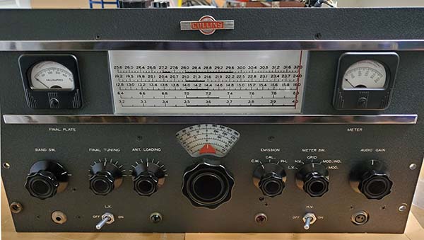
Quick Glance Identification of the 32V Series Transmitters: 32V-1 - Two toggle switches on front panel, two pilot lamps (green and red) on front panel, no grab handles. 32V-2 - Three toggle switches on the front panel, one pilot lamp (red) on front panel, no grab handles 32V-3 - No top lid on cabinet, two ART-13 grab handles on front panel |
|
Tube Line-up for 32V-1 1 - 6SJ7 - PTO, Oscillator For late versions add 2 - 0A2 - Screen Voltage Limiters |
Tube Line-up for 32V-2 1 - 6SJ7 - PTO, Oscillator For late versions add 1 - 0A2 and 1 - 0B2 - PTO Screen Voltage Regulators |
Tube Line-up for 32V-3 1 - 6SJ7 - PTO, Oscillator |
| The Different 15M and 20M Band Scales on the 32V Series - In 1946, the FCC was moving towards approving a proposal that gave amateurs a ham band in the 21 megacycle region of the spectrum. It wasn't known exactly how much spectrum was going to be available and the 15M band wasn't scheduled for actual amateur use until 1950 since the proposal had to also be approved by the IARU. As a result, Collins probably used what information they had during the design phase of the 32V-1 to produce a dial scale with 15M shown. It's noticeable that the 32V-1 and 32V-2 transmitters have 21.0mc to 21.5mc shown as the 15M band. The 32V-3, produced after 15M actually became a ham band, shows 15M as 21.0mc to 21.450mc which was correct. The 20M band had been 14.0mc to 14.4mc before WWII and apparently it was thought that no changes would be planned for that ham band. In 1950, probably a result of the same IARU meeting that approved the 15M band, the 20M band was reduced to 14.0mc to 14.350mc. The 32V-1 and 32V-2 show the 20M band as 14.0mc to 14.4mc while the 32V-3 shows 14.0mc to 14.350mc. The other ham bands on shown on the 32V Series dials are correct for band frequency limits used nowadays. |
|
32V Series - General Repair and Restoration Info |
|
|
|
What Can be Accomplished with Derelicts - Another Deplorable 32V-1 |
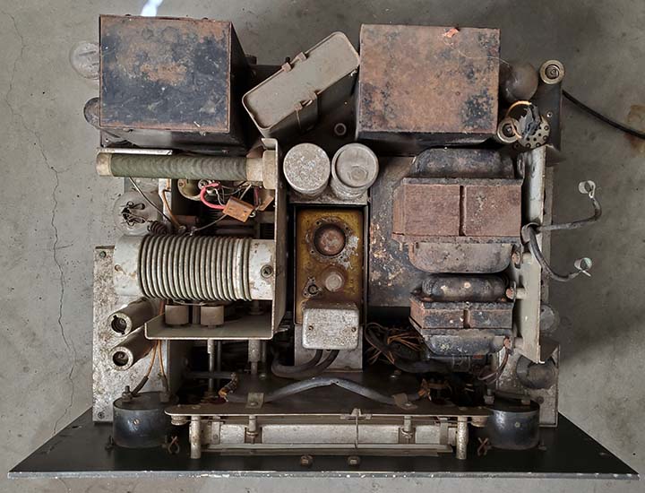
| The photos below show 32V-1 SN:373 recently restored by Steve Pazar W6SSP. This 32V-1 suffered from rodent infestation and a lot of corrosion. In addition, several components were defective. Steve did a complete "tear-down" of the V-1 into it's individual modular chassis components in order to better access parts, thoroughly clean, repaint and restore. Corrosion was removed with crocus cloth cleaning, scrubbing and lots of wire brushing. Some parts, like the silver-plated Multiplier and PA module chassis couldn't be cleaned in this manner since it would remove the plating. Each module was tested individually before reassembly. Although SN:373 was a very early version V-1, Steve added the two 0A2 Screen Voltage Limiters as used in the later V-1s. The 0A2s are located on the small chassis directly behind the PTO where the LV filters had been mounted. Other upgrades included replacement of the defective HV oil-filled filter capacitors using "plug-in" can replacements. The tube sockets for the plug-in caps mounted in the existing filter cap holes. Also, replacement of the vacuum tube rectifiers with SS replacements. Though this incredible restoration was time-consuming the results speak for themselves. In addition to this 32V-1, Steve also obtained a Collins 75A-1 in similar condition from the same source. This A-1 has also been restored. Thanks to Steve W6SSP for the photos |
|
|
|
|
|
|
|
More Restoration Information |
| Manuals - There are at least two different versions of the 32V-1 manual. If your 32V-1 has two 0A2 tubes next to the 5R4G tubes, then you need the later version of the V-1 manual. There are at least two different versions of the 32V-2 manual. If your 32V-2 has a 0A2 and 0B2 mounted on the metal cover of the Multiplier section (just behind the PA I meter,) then you need the later version of the V-2 manual. I've not seen the late version of the V-2 manual so it may not exist. A copy of the 32V-3 schematic would probably answer any questions about the PTO screen voltage regulators. There are at least two different versions of the 32V-3 manual. For some reason, the very early 32V-3 manuals don't have the 0A2/0B2 PTO regulators described in the text, however they are shown on the schematic. Any single manual might not provide complete information on your particular 32V transmitter. For late versions it might be necessary to have, for example, the 32V-1 and the 32V-2 manual since that will cover late upgrades to the V-1. All manuals are, for the most part, available either online or from vintage manual dealers. |
| Special Tools Required - Any serious rework on the 32V Series, or just about any piece of Collins equipment, will require the following special tools. First, a good set of Bristol wrenches. You will need the Xcelite Bristol Multiple Spline Screwdiver Set #99PS-60. This set is necessary because it has the extension required to access many of the set screws. This is an expensive set but an absolute necessity if you plan on working on Collins equipment. Next, you should have a 1/4" socket set that includes a phillips head fitting, a universal-joint and an extension of about 4" length. A fairly small phillips head right-angle ratcheting screwdriver has to be used when the 1/4" socket set won't fit into the area. Then, a small "C" clip removal tool will be handy to have - not a necessity - but handy. Of course the standards like a complete nut driver set, open-end/12 point wrenches, set of various size phillips screwdrivers and blade screwdrivers, quality wire side-cutters, various sizes needle nose pliers and a good quality wire stripper are always required tools. Additionally, an absolute necessity is a good soldering station - not a soldering gun - a good soldering station. Then only use high quality real SnPb solder (tin-lead solder, like Kestor.) Quality rework does require using the correct tools. Also, the proper tool will almost always make doing the particular task much easier. |
| Audio Modifications - None of the 32V Series transmitters require any type of modification in order to produce an excellent quality "ham" radio signal in either AM or CW. If you want your ham transmitter to sound like an AM Broadcast transmitter you won't be able to achieve that goal with any 100 watt ham transmitter. Most audio modifications might sound really great if you're receiving the transmitted signal via ground wave from a mile or so away. But, when that same flabby, bassy audio is modulating a little 100 watt carrier that is then propagated via skywave 500 miles or more, it becomes almost impossible to understand what is being said, even in good receiving conditions, let alone when there's QSB, QRN and QRM to contend with. The "communications grade" audio response was developed to allow relatively low-power transmitters the ability to produce an easy to copy signal that would be received in relatively poor conditions. And,...that's mostly what vintage ham gear operators have to listen to,...signals received in poor conditions. Leave the 32V audio alone. It's 200hz to 3000hz audio response sounds excellent and is easy to copy in poor conditions, which is what we have a lot of these days. |
| Capacitor Replacement - Most of the components used in the early 32V Series transmitters are WWII surplus parts. Generally, quality is first-rate, reliability is very good and seldom are capacitors a problem. The power supply filters are oil-filled paper capacitors and many of the other bypass capacitors are sealed, oil-filled units. Most resistors seem to be JAN types that usually don't drift in value. WWII surplus parts were around for quite a while, so even the 32V-3 seems to still be using many surplus components. I generally don't replace any of the WWII-vintage surplus components because they were "top quality" to begin with and seldom are defective. I did have one of the 4uf 600wvdc oil-filled filter capacitors in the LV supply in a 32V-3 leak oil. This was a mechanical problem and, while the capacitor still functioned as it should have, I replaced it because the seeping oil was creating a mess inside the transmitter. I replaced that "leaker" with a good condition, tested, WWII vintage 4uf 600wvdc oil-filled capacitor. The only 32V capacitors I've changed a few times have been the 2500wvdc micas in the Pi-L network in the 32V-2. The failure of these capacitors isn't the fault of the capacitor dielectric. The problem is caused by the Pi-L network and the ANT LOADING control design of the 32V-2. Other than those micas, I've never replaced any other capacitor in that 32V-2 in 25 years of casual operation (in other words, I didn't operate that V-2 everyday, just once in a while.) |
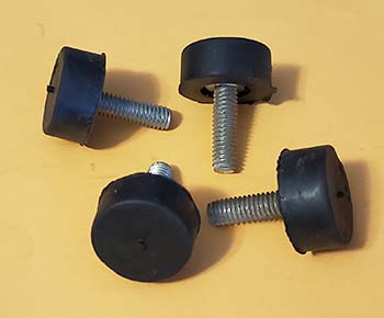
| Correct
Rubber Bumpers to Replace Missing 32V Cabinet Feet
- The correct rubber feet for the Collins 32V
transmitter cabinets were actually Threaded Stud Rubber
Bumpers that were 1" in diameter, 0.5" tall and had a
1/4x20 stud 1" long. The rubber bumpers were secured
using an external star locking washer and a 1/4x20 nut.
If you have to replace the rubber feet or you have a
missing foot, don't use the "hole mounted" type of
rubber feet. New correct rubber bumpers are available
from McMaster-Carr. They are listed as "Threaded Stud
Bumpers" but McMaster doesn't carry the exact
replacement. Although they carry the correct rubber head
size, the stud is too short. But, they do carry a 1"
diameter by 0.5" tall with a 5/16x18 stud 1" long. The
Collins cabinets are actually drilled for 5/16" studs,
so these work fine.
Replacement Rubber Bumpers for Collins 32V Cabinets |
|
|
Two Procedures for 32V Series Front Panel Removal |
| There's a procedure for
removal of the front panel in the 32V-3 manual. However,
there's no procedure for front panel removal in either
the 32V-1 or 32V-2 manuals. The 32V-3 procedure has you
note the position of the ANT LOADING and FINAL TUNING air
variables, the position of the turns counter wheel (only
used on the V-2 or V-3 versions) when
the associated coupler set screws are accessible and
related position of the associated knobs. This is
because the procedure has you leave the control shafts
in place since they used "C" clips on the
front panel side. Collins
assumed that most hams didn't have the proper tools to
remove the "C" clips but probably did have a screwdriver
(set screws are blade screws not the typical spline
socket set screws.) I hadn't seen the 32V-3 procedure when I first
worked on my old 32V-2. So, not knowing Collins' V-3
procedure and with the V-2 manual not having one, I came up
with my own way of removing the front panel. I did have
the correct tools for removing the "C" clips so I
removed them and left the shafts secured in the
couplers. That and the chrome strip removal is about the
only differences between the Collins procedure and how I
do it. Be
sure to check Pi-L network air variable C positions in
relation to the knob index positions before and after
panel removal. Collins Procedure with Two Slight Variations - Remove all knobs but be sure to note positions of ANT LOADING and FINAL TUNING knob index to panel index in regard to associated air variables in the Pi-network. Remove the two "C" clips on the ANT LOADING and FINAL TUNING shafts (use the correct type of removal tool.) Remove all panel screws including those under the lower trim strip. There are four panel screws located under the lower chrome strip. The strip doesn't normally have to be removed. Instead, just slide it to the right or to the left to access the panel screws. The upper chrome strip has two screws that normally have just enough clearance to remove without moving the chrome strip. NOTE: The Collins' procedure has you remove the chrome trim strips but I did break a spring clip doing this one time. Since then, I just slide the chrome strip to the side. Normally, the chrome strip has a very slight amount of clearance and doesn't contact the panel so no paint scratching occurs when sliding the chrome strip. Next, disconnect the wiring to the meter terminals (meters stay with the front panel.) Remove control mounting nuts on switches, controls and the key jack. Dismount the pilot lamp assembly or assemblies. The dial fiducial mechanism doesn't have to be dismounted. Front panel removal has to be done with care since there is a "snap-in" ceramic coupler between the VFO tuning and the tuned multiplier section. This coupler aligns with each shaft when the pto/dial assembly is bolted to the front panel. Since panel dismounting will allow misalignment of the shafts, it's best to remove the "snap-in" ceramic coupler while removing the panel (it will "pop" out of the clips anyway.) This necessitates having the transmitter on its side (RF output side up) while removing the front panel. This will require using spacer blocks between the chassis and the bench top so as to take the weight off of the front panel while its being removed. The multiplier slug rack is spring-loaded so it will drop to the high frequency end (slugs extended) when the "snap-in" coupler is removed. Be sure to have the VFO dial set to 4.0mc on the 80M band so a relatively correct slug position is maintained when the panel is remounted (the slug rack will only drop slightly if the VFO dial is set to 4.0mc on the 80M band.) You can mark where on the cam the slug rack rollers are positioned before you remove the front panel but if the dial is set to 4.0mc when the panel is removed then the correct orientation of the flex coupler will be obvious when doing the reinstallation. You'll have to manually move the multiplier slug rack slightly into the correct coupler engaging position when reinstalling the panel - do not change the VFO setting, only change the multiplier side to engage the coupler. When the coupler is in place then complete the panel installation. NOTE: You CAN'T remove or install the "snap-in" flex-coupler with the front panel mounted. This coupler has to be removed or installed as the front panel is either being dismounted or mounted. |
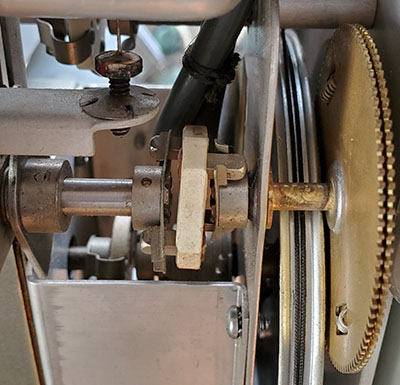
photo above: This shows the "snap-in" ceramic coupler (made by James Millen Mfg.) Note how the metal pegs fit into the clips of each shaft piece. Nothing holds this coupler in place except the spring tension of the clips and the front panel being mounted. With the front panel being mounted in position, the coupler can't be removed and it can't "fall out." Note that the shaft pieces are "pinned" to the shaft so they can't be moved. Also note at the top of the photo the hex head adjustment for the L, the slug for the first multiplier. |
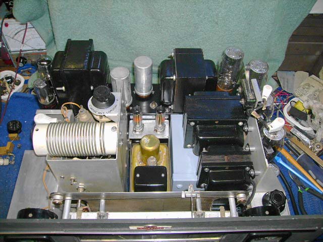
| Front Panel Removal and
Installation - Easier Alternate Procedure -
Steve Pazar W6SSP told me about his method of front
panel removal that might be prove easier since the PTO
and dial assembly
can be supported better in a vertical position. This
also allows the position of the "snap-in" coupler to be
worked with before the panel is actually mounted in
place. The procedure will require having the transmitter on its back and facing up. The rear chassis, the LV transformer and HV choke will have to have wooden blocks for spacers. Steve uses two 2x2s that are 12" long as the back blocks. When placing the rear support blocks be sure to avoid the terminal strip, the fuse holders, RF output connector and the toggle switch. Next, another short 2x2 with a thin foam pad is placed under the PTO to prop it up into position which allows easily inserting the "snap-in" coupler. Be sure to observe the proper positioning of the Multiplier slug rack and to have PTO frequency dial set to 4mc (as described in both procedures.) Then the coupler should align and "snap-in" the proper position. With the coupler installed, then the front panel can easily be placed in position and all of the mounting screws installed.
Steve sent me his complete, "step-by-step" procedure for complete tear-down of a 32V transmitter. It follows in the next section,...
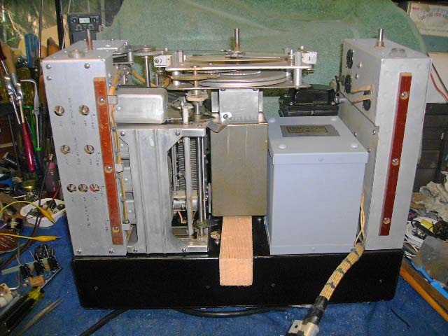
photo right: Steve's photo showing the 32V-1 in position ready for the front panel to be installed. |
 |
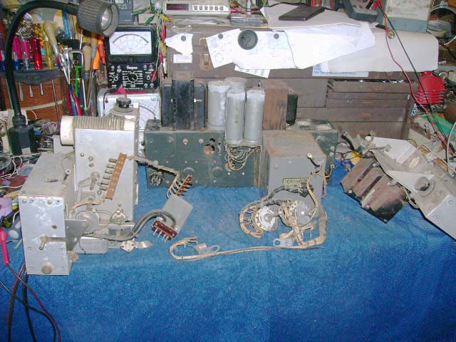
| Steve Pazar's
32V Step-by-Step Tear-down Procedure The 32V transmitters are made up of 5 subassemblies, front panel, power supply, PTO/dial, modulator and RF sections. The only way to disassembly these transmitters is to first remove the front panel. This is the most difficult part but once it's off, everything else is easy. Front Panel Removal * From the bottom
(place TX on its side), set dial to the highest freq
tick (right side) and mark the slug rack position to
help with reassembly > from the top (TX bottom down with front panel 1"
over edge of bench) |
PTO/dial removal * remove the octal plug going to mod chassis on right * remove the metal module on top of the PTO (2 screws and standoffs) - it unplugs from the PTO * locate string going to pulley as left (band pointer drive) remove the string at the bottom of the plate below the pointer (on dial assy) - it's threaded through two slots and just pulls loose, set it aside but leave connected to pulley end * remove the mode switch (ceramic, mounted on second plate behind dial) by removing the nut and lock washer, pull it loose with its harness,...can be set aside * at this point the PTO/dial assembly can be removed
Modulator removal RF Module removal At this point you will have the power supply, the RF module and the Modulator module separated as individual units. The PTO and tuning dial will be separated from the front panel and from each of the other modules. This will allow detailed rework because of much better access to all components. Thanks to Steve Pazar W6SSP for contributing his 32V Tear-down procedure I have another alternate procedure that was submitted by John Keating K7LY that I'll add. I have to convert the procedure from a word document to a HTML doc. Coming soon. |
|
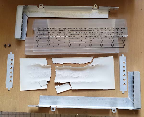
32V Series "Band-in-Use" MC Dial Repair When I purchased this 32V-1 it looked in excellent condition,...and it was,...for the most part. But, like almost all 32V transmitters, the slide rule dial had seen better days. Here is a detailed description of how to rebuild the slide rule dial on any of the 32V transmitters,...they're all basically the same. Part numbers for the velum and the white plastic material are from Michael's but there should be enough information provided to find similar products elsewhere. |
|
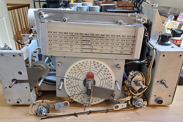
The "band-in-use" MC dial illumination and slide rule dial/band-in-use assembly is virtually identical for all of the 32V Series (and it's very similar for the 75A-1 dial.) Rebuilding the slide rule dial assembly will require its removal from the transmitter and that will require dismounting the front panel. The front panel removal procedure is covered in the section above this one. Once the slide rule dial assembly is dismounted from the chassis (four screws and nuts,) its disassembly can be started. The photo right shows the 32V-1 chassis with the front panel removed. Note that without its mounting to the front panel, the PTO-tuning assembly is just setting on the bench although the cables and connecting wires will keep it from moving too far. The dial fiducial actuation string and spring can be seen. It isn't necessary to dismount this mechanism but do observe the string placement as it can easily come off of the pulley. To remove the dial assembly from the chassis first remove the clip-in lamp fiberboard connectors. This might allow the #328 dial lamps to fall out of their holes. It doesn't matter too much but try to keep the lamps in place until the dial itself is dismounted. The two top screws and nuts that mount the dial also have cable clamps on the backside. The bottom screws and nuts have stand-offs associated with their positioning. The bottom screws are difficult to access. On the 32V-1 you can tilt the PTO-tuning assembly somewhat forward to have the screw heads in a better position to access. With the 32V-2 or V-3, due to the turns counter dial and shaft, you can't tilt the PTO-tuning assembly forward very much. On the V-2 and V-3 you have to use a right-angle phillips head screwdriver to access the bottom two screws. You can also use a 1/4" socket set with phillips head fitting, a universal joint fitting and extension. |
 |
| Once the dial assembly is dismounted it can be disassembled.
The slide rule dial assembly is held together with two aluminum extrusions that have
a right-angle bend so when the two pieces are together they form a
rectangle that will hold the remaining pieces. Eight plexiglass
square rods are transparent on three sides and on the ends while the fourth side is
frosted. The plexiglass pieces are stacked together with the frosted
sides facing forward. Next a piece of vellum placed between the
frosted-side of the plexiglass and the glass dial. Behind the plexiglass
stack (against the clear transparent back) is another piece of
vellum and then a piece of opaque white plastic sheet. On each side
is a metal mask that has holes for the light from each of the ten
#328 dial lamps. This series of components are held together in the
aluminum extrusion with the two aluminum pieces mounted together
with two small screws. The assembly shouldn't bind or put pressure
on the glass dial when assembled. You should actually be able to
move the glass dial slightly within the mounting. The dial assembly shown to the right was removed from the 32V-1 transmitter. Note that the vellum pieces are missing from the assembly. This is why when looking at the photo above it appears that there are "stripes" in the dial background. The darkish area in the center around 20M, 15M and 10M is caused by the warped white plastic back. Looking at the photo left, it can be seen that without the vellum spacer behind the plexiglass rods and in front of the plastic, the plastic will eventually stick to the plexiglass. That's why the white plastic broke into pieces when removed (also, it easily broke because of the warp and heat-induced brittleness.) The vellum in the front protects the dial nomenclature and also provides an even background when illuminated. It's obvious that this dial assembly has been apart before and that's probably why the vellum is missing. Also, probably why the next problem exists,... It probably can't be seen in the photo but one of the clips that retains the fiberboard dial lamp power connector is broken. There was a "hamster" lash-up involving a flat spring and wooden dowel spacer that kept minimal pressure on the connector so the lamps on that side would stay illuminated. At least no holes were drilled for this "hamsterepair." Fortunately, I do have a 32V "parts set" that can donate another aluminum extrusion piece when this dial assembly is put back together. |
 |
Each of the plexiglass square rods
has to be individually cleaned with Glass Plus to assure good
illumination. Replacements for the vellum and the white opaque
thin plastic can be found at any hobby store or any "arts and crafts"
store. My source was Michael's, which is a large "hobby-craft"
store-chain that has shops almost everywhere. You can also order "on
line" from them. Here are the Michael's part numbers:
Vellum Paper Sheet - 8.5" x 11.0" - Recollections Signature Especial
- PN: 10268562 Bar Code #86946
55305
White Plastic Sheet - 22" x 28" - CREATOLOGY - PN:
US-WI-1118-56475-0378146-01 Bar Code #86946
69254
WARNING: DO NOT USE
WATER OR ANY LIQUID when trying
to clean the nomenclature side of the glass dial. The dial scale is
applied to the glass as water-soluble ink silk-screen application. Clean
only by using a soft paint brush or soft dry cloth to remove the
dust. You can clean the front of the glass dial with a Glass Plus
dampened paper towel. If the backside of the glass dial is
carefully cleaned with a dry soft flannel cloth no damage to the
nomenclature will occur - don't scrub, just light rubbing motions
will remove most dust-film. Shown to the right are all of the pieces to assemble the dial. The new front vellum piece is behind the dial glass and the cleaned plexiglass square rods are behind the vellum. Above the dial is the new rear vellum piece and the new white opaque plastic piece. The dial lamp masks are the shown along with the two extrusion pieces and the two screws and lock washers. |
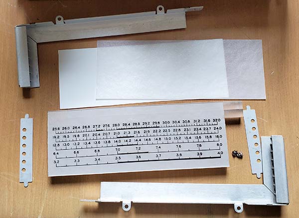 |
| When reassembling the dial, note that the metal lamp masks can be
installed two ways. The correct position is with the holes nearest
the front of the dial assembly. That way when the #328 lamps are
installed their filaments will just be visible through the hole and
will shine down the plexiglass square rods. If installed with the
mask holes nearest the backside of the assembly, the holes will
align where the glass envelope meets the top of the lamp metal base
and the light from the lamp will be scattered and not as bright as
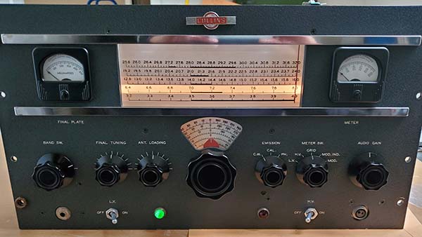
it should be. Be sure all contacts are clean on the #328 lamp conductive strips and the contact finger assemblies. I use a brass "toothbrush" to clean the contact fingers and the conductive strips. Once everything is clean and assembled with new pieces for the vellum and opaque white plastic then the dial assembly can be mounted in the transmitter chassis. It's easier to mount the dial assembly with the transmitter setting right-side-up on the bench. The bottom two screws and standoffs are difficult to get into position. Long needle nose pliers that are thin enough to fit between the back plate and the back of the dial will help get these two standoffs in position. Don't tighten the four mounting screws at this time, just snug is okay. Next, the ten new #328 lamps are "loaded" into their respective silver-plated conductive strips and then loaded into the dial assembly. Then, the two #328 dial lamp contact retainers can be snapped into place. The silver-plated conductive strips help the chassis ground return for the ten dial lamps and prevent "blinking" or intermittently illuminated lamps. The next step is to remount the front panel. Use the reverse of the procedure in the section above this one and observe the following details. Front panel installation has to be performed with the transmitter chassis on its side with the RF side up. This allows easy observation of the multiplier cam and slug rack rollers which is where the "snap-in" flex-coupler has to be inserted as the front panel is mounted. The clips in the multiplier side of the coupler will hold the ceramic "snap-in" piece which then allows the front panel to be guided into position and engage to flex coupler. The multiplier slug rack cam has to be hand-moved into position for the flex coupler to engage. With the VFO set to 4.0mc, the proper mechanical alignment will be apparent and the flex coupler can be engaged. It's easier if a temporary cardboard spacer is placed under the PTO (between the PTO and the HV transformer) to have it "resting" in the proper position for mechanical alignment. Once the flex coupler is installed, the rest of the front panel screws can be installed. Watch the mechanical alignment as the panel is tightened to make sure there's no binding taking place. Install all control and switch mounting nuts. Install the "C" clips on the FINAL TUNING and ANT. LOADING controls. When installing those knobs verify that, with the knob index at the left side panel index line, the respective air variable capacitor is at full mesh. Install the remaining knobs. Connect the meters. Once the panel is mounted, check that the dial scale base lines are parallel to the chrome trim pieces. If not, loosen the four screws that mount the dial assembly and move it to a position where the dial scale base lines are parallel with the trim pieces and then tighten the screws. After the rebuild and with the assembly reinstalled into the transmitter, the "band-in-use" MC dial illumination is bright and the dial background is all the same color with no "dark areas." The two photos to the right show the 32V-1 dial after the rebuild. Top photo with the rig OFF. Note that the dial background is even with no dark spots and the dial nomenclature is easily readable. Bottom photo with the rig ON. Obviously on 40M (although tuned to 8.0mc,) note that the illumination is even and bright. All bands are illuminated evenly at the same level of brilliance. |
|
|
32V Series Alignment |
| Before starting the alignment, test all of the tubes in the transmitter and replace any tubes that test low or are defective. Be sure to test the PTO tube (6SJ7) located under the shield cap on top of the PTO. The alignment procedure starts with checking the end-point error of the PTO. The adjustment is easily accessed on the 70E-8A or B PTO by removing the cinch-plug on top of the PTO on early models and by removing a triangular shaped cover secured with three screws on top of the later models. The procedure requires a receiver with an accurately calibrated frequency readout to monitor the PTO output frequency. The object is the have the PTO track from 3400kc to 4000kc in exactly 12 turns. The receiver monitors the PTO fundamental frequency of 1700kc and 2000kc. It's also very easy and accurate to use a digital frequency counter connected to the PTO output. Use the fundamental of 1700kc to 2000kc accomplished in exactly 12 turns. The 32V manuals provide a "quick" method for PTO adjustment that Collins used at the factory for end-point error reduction. It's very easy to use, works really well and eliminates the time-consuming "trial and error" approach to reducing the end-point-error. Once the end-point error is less than 1kc (preferably < 0.5kc) then the multiplier section can be peaked. There are .250" hex adjustments for the L and ceramic trimmers for the C. The manual's procedure is very easy to follow. Depending on how much adjustment is required, it might be necessary to adjust the two harmonic-spur C trimmers. These are very narrow adjustments that have the multiplier output monitored at a specific frequency on a receiver and then the trimmers are adjusted for minimum signal as measured on the receiver's S-meter. The procedure in any of the 32V manuals is easy to follow. |
|
32V Series - Restorations, Operational Characteristics and Critiques |
|
32V-2 SN: 1142 |
Purchased in 1993 - I've owned the 32V-2 transmitter shown in this write-up since 1993, about 27 years. It had been listed on the West Coast 40M Swap Net and the info was relayed to me by telephone from NU6AM. I called the owner who lived in Pahrump, Nevada. The price was $200, which I agreed to. We decided to meet halfway between Pahrump and Virginia City which happened to be Tonopah, Nevada. Our rendezvous point was in front of the famous Mizpah Hotel, a landmark in Tonopah. I took W7TC (SK now) along as co-pilot for the trip down to Tonopah. We left at 7AM, met up with the "V-2 seller" at the Mizpah at 10AM to complete the deal and, after a lunch break at the El Capitan in Hawthorne, Nevada, Tom and I were back at our respective homes by 4:00PM in the afternoon. The 32V-2 was operational but just barely. While it worked on 80M and 20M, it didn't work on 40M. The problem was a blown fixed value cap in the Pi-L network. The kilocycle dial was severely discolored (reproductions were available at that time) so a repro KC dial was installed. I rebuilt the slide-rule dial assembly with a new plastic back (but I didn't replace the velum - and I should have.) I touched up the cabinet paint. I probably replaced a tube or two. I then began using the V-2 on the old Saturday Morning 3870 AM Net. Since then, I've worked on the V-2 many times over the years. It is mostly original but has one capacitor "added" in the multiplier and I've had to replace the Pi-L network micas on a couple of occasions. I did have intermittent operation that was caused poor condition contacts on the auxiliary control relay. I used to have to clean the contacts about every three months. Finally, I found a good condition original 32V relay to replace the intermittent one. I've probably replaced the 4D32 PA a couple of times over the years. Once all of the problems were repaired the 32V-2 was a reliable, good sounding transmitter. It also looked pretty good (photo to the right.) Minor issue - The 32V-2 isn't as well regulated as the later 32V-3. Consequently, when initially actuated at full power with +700vdc plate voltage using the PTT, the carrier frequency will slightly drop a few hz and rapidly drift back up to the set frequency (kind of like a "bloop.") It's hardly noticeable and I've only had one contact in years of using the transmitter ever mention the "turn on" frequency bloop. You'd have to have the receiver BFO on or be looking at a panadaptor to notice the frequency drop since it isn't audible on AM. I've noticed the frequency drop for years but since it's only a few hz and quickly returns back to the set frequency in just a couple of seconds I was never concerned about it. It's more noticeable on CW but again it corrects itself within a couple of seconds so never any mention from contacts. >>> |
|
|
32V-3 SN: 1367 |
Purchased in Apr 2018 - I've owned this transmitter for only a couple of years. I only restored it last summer (2019) so I haven't operated it nearly as long as the 32V-2. I purchased the 32V-3 from Ham & Hi Fi in Sparks, Nevada. It was in superb cosmetic condition but its operational condition was unknown. The two 807 modulator tubes were missing so I checked the modulation transformer before purchasing the transmitter. When powered up the 32V-3 had a significant auditory "buzz" but the RF output had the correct meter readings and the carrier looked good on the 'scope. I had to replace the two 4uf 600vdc oil filled capacitors in the +LV supply because one of them was leaking oil,...quite a lot of oil judging from the residue that needed to be cleaned up. I used the 32V-3 a few times but the "buzzing" was annoying. Later, when moving the transmitter, my hand happened to bump into the slide rule dial "glass" and it actually bent. A couple of "knuckle thumps" to the dial cover convinced me it was thin plastic. I couldn't believe it,...nobody restoring a Collins transmitter is going to install thin plastic sheet where originally glass was installed,...but whoever worked on this V-3 did. This had me motivated to correct most of the problems that I had run across over the past year of ownership. I rebuilt the entire slide rule MC dial assembly with new velum, new white plastic sheet, cleaned plexiglass square rods and new #328 dial lamps (ten of them.) New glass was installed into the front panel to complete the slide rule dial transformation. Also, the dial pointer was devoid of any paint so I painted it the correct "dark red." The "buzzing" issue was caused by L303 which is the input choke on the +HV. A choke input filtering system will sometimes produce a mechanical buzz and a swamping capacitor (or resonator cap) is part of the circuit to reduce the buzz. But, this 32V-3 was a particularly loud "buzzer" that the capacitor only slightly muffled (the oil-filled cap was checked for correct value.) I removed L303 and tried various other 5H chokes (connected outboard with test leads) until I found one that didn't buzz (actually the second one I tested.) The old choke was melted out of the housing and the new choke installed with most of the black wax re-melted and poured back into the housing. The new choke is much quieter producing a "soft" buzz when the transmitter is at full output power. Since the front panel was dismounted for the dial rebuild, I had to touch-up the multiplier alignment. The 32V-3 is now a pleasure to look at and a real pleasure to operate. Always gets good audio reports and the stability is rock-solid. I've only operated it on 75M and 40M but those bands work great. 32V Series transmitters will always have powerful audio. It's very easy to "over-modulate" the carrier. An oscilloscope should always be used to monitor the signal to assure that the modulation level is not so high that "cut off" is happening. Meters can't respond fast enough to indicate modulation levels accurately. The 'scope gives an instant visual representation of the carrier and modulation level. |
|
SN: 1367 Back on the Bench - Apr 2020 - There were a few things on the 32V-3 that bothered me enough that I had been wanting to revisit the initial restoration for quite a while. I had just recently found a 32V-2 "parts set" that had been in the poorest storage possible for decades and that had relegated it to "parts set" status. It was a very late version V-2 so it had many parts that were identical to those used on the V-3. Having a good parts source was certainly the major factor in deciding to go ahead with the "revisit." The first problem with the 32V-3 was the 4kc error in the dial frequency readout on 80M. This must have been there all along but I hadn't noticed for some reason. After setting up the V-3 and actually trying to set up on a net frequency, the 4kc error became very apparent. The second problem really wasn't a serious problem but T301 was a replacement from an earlier version, probably a V-1, transmitter. It functioned fine but it was visually apparent that the transformer wasn't the correct vintage for the V-3. Additionally, the replacement T301 had the LV CT wired back to two unused pins on the rear terminal strip (pins 13 and 14) which then required a jumper to be installed on those pins for the LV to work. This mod used 14 ga plastic insulated wire and was probably to allow the use of a remote switch that allowed the tube heaters to be on but not the LV. When the transmitter was ready to use, then the remote switch was closed and LV was applied to the transmitter circuits. Some hams used to believe that tubes lasted longer if they weren't cycled "on and off." I do know of one ham who left his 32V-2 transmitter turned "on" 24/7 - that is, until a few months later when he had to replace several of the tubes and he had only been "on the air" a few times. This CT mod will be removed and the wiring returned to original. Another problem was the interlock switch which was damaged. I had removed the two interlock wires and soldered them together bypassing the interlock altogether. In checking the interlock switch it had merely broke one of the retaining rivets. It would function fine if the rivet was replaced and this would allow the interlock to be in place again. A very minor problem was the broken retaining clip for the upper chrome strip. I made a replacement that worked but didn't look original. Now, an original retaining clip can be installed for the chrome strip.
|
 |
 |
On the bench, out of the cabinet and with the perf-metal covers removed, I checked the PTO output and found that it tracked perfectly. All that was required was to set the kilocycle dial correctly. I just loosened the dial set screws to move the dial to the correct position. Retesting had the PTO tracking the entire 80M band with <1kc error. I did check to make sure the coupler set screws were tight also. Can't explain the 4kc error but it was easily corrected. The interlock switch was repaired by drilling a #49 drill hole down into the solid body of the broken rivet. Then a 2-56 tap threaded the hole and a 2-56 x 3/16" screw was installed to pull the switch back together. After testing, the switch was installed and wired back into the circuit. The chrome strip clip only required removal of the strip, removing the homemade clip and installing the original clip. Then the chrome strip was installed back onto the front panel.
T301 had to be harvested from the very late version 32V-2 parts set
that had the correct square housing (potted) version of T301. Upon removal,
this T301 had to be thoroughly tested since the condition of the
parts set was "challenged." I also removed L303 from the parts set
since it also was the correct square housing (potted) style and it was also
thoroughly tested for the same reasons. Both components tested good.
T301 was powered up and left on (no load) for about 20 minutes. No
heat build-up and the operation remained quiet. |
|
Next was to repaint these "new" T301 and L303 since they were in rough condition externally. The housings were prep'd for painting with matte black used for the color. The two units were ready to install but I let them set for a couple of days to let the paint cure. The next step was to identify with wrapped tape where all of the connecting wires went to as I removed the earlier version T301. Luckily, T301's terminals (on both styles) are mounted on a terminal board that is mounted to and under the transformer and these terminals are numbered on the board. Unfortunately, removing either T301 or L303 is a challenging job because two of the mounting screws are at the back of the chassis and buried behind other wiring harnesses or other components. The auxiliary relay has to be dismounted, the component board in the center of the chassis has to be dismounted, the 5Z4 and 0A3 have to be removed...even then harnesses and other wires have to be moved around to access the mounting hardware. A right angle phillips head ratcheting screwdriver works best for access the back screws but also a 1/4" socket wrench with a phillips socket might be needed. T301 can be tilted to the side and then the wires unsoldered with identifying tape installed as each wire is detached. There are 11 terminals but many terminals have several wires attached. To protect the chassis paint, install a couple of masking tape strips where T301 is resting on the chassis during the removal process. L-303 only has two wires, one to the rectifiers and the other to the filter capacitor. |
|
T301 and L303 replacements are installed first. I installed the mounting screws finger tight first (hint: put one drop of 3-in-1 oil on the screw threads and they'll screw in easily.) I then put the 32V-3 on its side (RF output side up) and then tightened the mounting screws. It's easier to see the fit of the screwdriver head with the transmitter on its side. Next, I reconditioned all of the wire ends. This is removing old solder, straightening the wire, twisting the end and tinning it. This assures a good connection and no broken wires. I soldered all of the wire connections to T301. I removed the ID tape as each wire was soldered so there was no confusion as to what wires went where. Since I had removed the CT mod wires (the 14ga plastic insulated wires) I connected the two CT wires to T301, as original. L303 was easy since there are only two wires. The wire ends were reconditioned, tinned and then soldered in place. The entire power supply chassis was cleaned inside removing all solder and wire pieces, cleaning all dust and dirt and checking all other wire connections. I found that the CT connection on the PTO tube filament transformer was only connected by one strand of wire. This wire end had to be reconditioned and resoldered. There was a non-original 14ga wire with plastic insulation (same as the CT mod wire) connecting the LV fuse to the AC line input. The original was 22ga with fabric type insulation. I removed the 14ga wire and replaced it with a more original type of wire. I then wrapped black lacing on that particular part of the harness so that the wires stayed in a bundle. The PTT relay, the component board, the PTO tube filament transformer and the rear bottom chassis piece were all remounted back in place. This completed the rework. Testing was going to check to make sure I connected T301 up without any errors. I pulled the HV rectifier tubes and the 5W4 LV rectifier tube. Then I attached the AC power cable and powered up the 32V-3. All lights and tube filaments came on indicating that the filament windings were correct. I checked the LV rectifier tube socket, pin 4 to pin 6 and measured about 900vac no load and about 450vac from chassis to each tube socket pin. This indicated that the high voltage winding of T301 was wired correctly (+240vdc under load for +LV.) The rectifier tubes were installed into their respective sockets and the 32V-3 powered up. I connected a dummy load. I had to hold the interlock switch closed and in the TUNE position I had about 125mA of plate current with the key down. In the OPERATE position I had about 200mA of plate current key down. Reassembly was completed and the 32V-3 was now ready to use. It also is now very nearly 100% original,...well, original Collins-type and correct vintage parts anyway. Photo right shows the 32V-3 chassis after completing the rework. I'm still missing the two rear terminal covers (which I'll probably have to fabricate.) |
|
|
32V-1 SN: Unknown |
Mar 2020 - After seeing several examples of 32V-1 transmitters over many years going to ham swap meets, all with varying degrees of "hamstering," parts salvaging or with condition problems resulting for storage outside, it was a nice surprise to run into this example at Ham & Hi Fi in Sparks, Nevada. Close examination revealed an all original, extremely nice condition transmitter that only had a couple of minor issues. Seeing that the two 0A2 regulator tubes weren't flanking the 5R4 rectifiers identified this V-1 as an early version. Even the red paper string tag was still on the ANT COARSE LOADING control. Unfortunately, when pulling it off the shelf for examination of the rear it was noted that the serial number tag had been removed. However, all of the rear covers were present which is rare. Of note was the fact that the antenna coaxial cable was still connected, the Dow Key relay was still connected to the rear terminals and the receiver standby wires were also still connected. It looked like this V-1 had been in use - recently. Considering the completeness and exceptionally nice condition of this V-1, a reasonable price was agreed upon and I took the transmitter home. Moving a hundred pound rig does take a bit of caution. When moving is required, I always take the transmitters out of the cabinet on any of the 32V series since that reduces the weight to about 80 pounds for the transmitter and about 20 pounds for the cabinet. Once upstairs on the bench, since the transmitter had the appearance of being recently in operation, a dummy load was connected and the 32V-1 powered up. I had the +HV set on +600vdc and since the V-1 doesn't have a "TUNE" position, I reduced the ANT COARSE LOADING to 1 to start off. I used a small "pinch" clamp to hold the interlock closed since the transmitter was out of the cabinet. I checked 80M, 40M and 20M and found the transmitter worked very well in CW. I did note that the calibration was close on 80M and 40M but 20M seemed to be quite a bit off leading me to believe that probably 10M and 15M would be even worse. I checked phone operation on 80M and the modulation level was good and the audio sounded fine in the monitoring receiver. Now, as to what work was required,... The slide rule MC dial looked sort of original but the white plastic backing has warped and distorted severely, which is typical for original dial assemblies. It turned out that the dial assembly had been worked on in the past and the vellum pieces removed. Also, a weird lash-up using a flat-spring and wooden dowel held the rightside dial lamp power connector in place since the original retaining clip was broken. I ended up replacing the lower extrusion piece (parts set harvest) so I would have a good condition retaining clip for the dial lamp power connector. So, the slide rule dial assembly was rebuilt. The kilocycle dial had a very slight discoloration that was barely noticeable. The dial was not replaced since repro KC dials aren't available (as far as I know - a source isn't listed on the Collins Collectors website.) When I had the front panel off, I cleaned the kilocycle dial which helped the discoloration almost to the point of invisibility. The transmitter chassis was fairly dirty - not like it had never been cleaned but certainly dirty enough to require cleaning, especially in the +HV areas. Multimeter switch was intermittent on +LV, so all switches and controls were cleaned with DeOxit. Since the front panel was off which affects the multiplier tracking a complete alignment had to be performed. The PTO checked out with < 1kc end-point-error so adjustment wasn't necessary (or so I thought.) The multiplier was fairly close on 80M and 40M but not very close on 20M and 15M didn't even work because the multiplier adjustments were off significantly. At least 10M functioned but was also pretty far off. Once the multiplier was aligned, the transmitter functioned on all bands and loaded up the dummy load to full power on all bands although, as would be expected, power output on 10M is less than on 80M. I switched to +700vdc HV and tried 80M with no problems. Checked modulator bias and found it set to 100mA which is about double where it should be. Reset the modulator bias to 50mA since I intended to run the V-1 in the +600vdc HV position. Power output (with NOS 4D32) was 80 watts at 180mA PA I. The 32V-1 was ready to put "on the air." >>> |
|
| 32V-1's Maiden Voyage Turns Up Problems
- Apr 5, 2020 - Nothing like "sea trials" to
actually see how a new rebuild is going to function. It wasn't long at
all before I discovered the same problem with the 32V-1 that I had had
with the 32V-3 which was the PTO frequency accuracy. This time it was a
7kc error. The problem was with how I was checking the accuracy. I was
using a Collins R-388 which wasn't the problem. The problem was that I
wasn't using the Crystal Filter to narrow the IF bandwidth. As a result
I was trying to find a peak signal response with an IF bandwidth of about 8kc.
Obviously accuracy suffered a lot. By switching the Crystal Filter to position 4
(narrowest position) and
narrowing the bandwidth to absolute minimum with the Phasing, I was able to
achieve <1kc bandwidth. Once I was able to tune the R-388 calibrator
in accurately, then I could also tune in the 32V-1 accurately. With all
of this "dead on" tuning, I discovered that the PTO had an
end-point-error of 3kc between 3.4kc and 4.0kc. I used the "Collins
method" and was able to achieve 0.3kc (300hz) end-point-error in one adjustment. The "Collins method"
is described in the manual (simple math involved and well worth the
effort.) I then adjusted the KC dial to show "0" on
4.0kc. Dial accuracy is now quite good. The next problem occurred when PTT was actuated. The "growl" heard actually showed up on the 'scope. It turned out to be the DowKey relay was "chattering" and that had the arm of the relay bouncing on the transmit contact of the DowKey which was what showed on the 'scope and was heard by the receiving stations on the net. I had a couple of other DowKey relays that I could try. One had a missing transmit contact on the internal arm so I couldn't use that one without rebuilding it. The second looked good and worked quite well. Another strange occurrence that really wasn't a problem, just kind of weird. I kept hearing a "ringing" sound that strangely sounded like a very quiet "bicycle bell" when the transmitter was at full power into the dummy load. Unbelievably, the two 5R4G rectifier tube envelopes were barely touching and the mechanical vibration of the transmitter under load somehow imparted enough vibration to the 5R4G tubes that their envelopes were barely bouncing together. The best description is that it sounded like a quiet bicycle bell ringing. With the two 5R4G tubes squarely installed in their sockets the two tube envelopes don't touch, though they are very close together (~ 1/8" clearance.) Just a weird one. |
| Wrap-up - The
Collins 32V Series was produced for about 8 years. During that time,
ham radio was changed forever by the introduction and massive growth of
television "over the air" VHF broadcasting. The problem that faced the
ham radio manufacturers was
how to build a transmitter that could be operated in a neighborhood
filled with "roof top" TV antennas. What's interesting about the
32V Series, as a whole, is seeing the evolution from the 1946 32V-1,
with its lack of effective shielding and a large harmonic output, up to
the 1953 32V-3, with its ability to operate, for the most part, in TV-land
without upsetting the already constantly complaining neighbors. Luckily, today's
HDTV broadcasting, microwave satellite signals and the almost universal
use of
cable TV providers have relegated TVI to something that is rarely, if ever,
experienced. However, that hasn't changed the TV-watching public's contemptuous view
of the ham radio operator one bit. One only has to look at the rules of most HOA-governed
neighborhoods. Ham antennas and, many times even "ham radio operation,"
is forbidden in all of these types of "group-controlled" housing developments. So, the
next time you're working on your 32V-3, with the two perf-metal shields
removed and that pile of 20 hex head self-tappers and seven 4-40 machine
screws setting on the corner your work bench, just remember that, back in 1953, all
of that extra sheet metal had to be installed just so the original ham owner
could operate that 32V-3 "on the air" in TV-land. Usually in the "wrap-up" I write about the particular piece of gear and not the how and why of its evolution (along with a tirade on TVI.) So,...what about the 32V transmitters? First, they were expensive,...priced from around $575 to start (the 32V-1) and increasing to an amazing $900 for the last list price for the 32V-3. Were the 32V Series better than any other commercially-built ham transmitter? When it came to the circuit design,...it was the most advanced medium power ham transmitter available. And, as for build quality, Collins was hard to beat. The materials used were the best (except for the photosensitive plastic KC dials,) the components were from the best companies (naturally, since many of the components were WWII surplus parts,) the wiring harnesses were beautifully routed and laced (which sometimes complicates reworking,) paints and finishes were excellent. But, what about performance? Most vintage gear operators seem to agree that the Collins 32V Series are excellent performers with advanced designs, dead-on frequency readout accuracy and great stability. They are easy to operate rigs with very powerful audio that can easily achieve 100% modulation levels while producing an excellent stock audio response. Where the collectors seem to have somewhat diverse opinions about the 32V Series is the mechanical design complexity that makes the transmitter very difficult to work on,...even for routine maintenance. There's no doubt that it will take a lot longer to rebuild any 32V transmitter if that rebuild time is compared to, e.g., a Viking I. But then, when comparing the end results, on the air, a stock Viking I doesn't sound anything like a stock 32V. I guess the conclusion is that for those vintage ham radio collectors that really, really (and I mean really) relish the disassembly, repair, rebuilding, fixing, adjusting, reassembling and aligning of vintage gear, the 32V Series will give you plenty of opportunities for lots of enjoyment. If using that gear to produce a first-class sounding signal (and looking great while doing it) is the ultimate goal, then the Collins 32V Series will also be appreciated and admired,...after the work is finished,...by someone else. |
photo above: W5AXI/HK1 QSL card from May 1950. Lots of photos on Hutch's QSL. Apparently, he sometimes operated Maritime Mobile from the S.S. Fullerton Hills but this QSL confirms his 10M contact from Covenas, Columbia, South America with W2YDU. Besides his photo "in uniform," the S.S. Fullerton Hills and his station are also shown. Of interest is Hutch's use of the Collins 32V-1 transmitter and the Collins 75A receiver. The QSL indicates his antenna was a "LONG WIRE." At least a good use for the Hallicrafters S-38 was to use it as a pedestal for the Collins 270G-1 loudspeaker. Also note the D-104 on a really tall stand and the bug looks like a Vibroplex Original. The book in front of the 32V-1 looks like a Call Book. Another bit of trivia,...the font used for the typewritten parts of the QSL indicate that a WWII "Mill" typewriter was used - all upper case and the characteristic "curled-top C." Unfortunately, no Ø anywhere on the QSL.
|
|
|
Radio Boulevard
Western Historic Radio Museum
Vintage Radio Communication Equipment Rebuilding & Restoration Articles,
Vintage Radio History and WHRM Radio Photo Galleries
1909 - 1969
- 60 years of Radio Technology -
This website created and maintained by: Henry Rogers - Radio Boulevard, Western Historic Radio Museum © 1997/2026