|
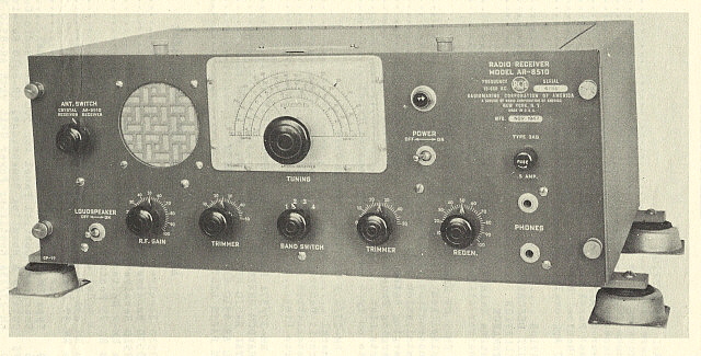
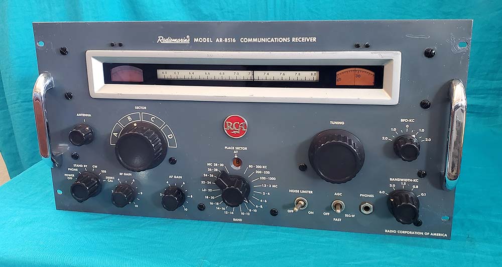
Radiomarine Corporation of
America - Model AR-8516
Circuit Description
- RMCA introduced the AR-8516 around 1958 and it was
available up into the mid-1960s. It was a
tremendous upgrade from the proceeding commercial shipboard receivers
that RMCA had been providing (those designs dated from the early part of WWII.) The AR-8516 was
a thoroughly modern, complex communications receiver that used 18
tubes in a single, double or triple conversion superheterodyne circuit. The
receiver used a variably-tuned IF covering 1.09 to 3.09mc or 2 to 4mc.
The fixed-frequency IFs were at 455kc and 45kc. Single conversion was
used in the first five bands covering 80kc up to 4mc. Bands 1-4 span
different widths of the LF and MF spectrum and, along with Band 5, these
single conversion bands tune from left to right being from high to low
in frequency. From 2mc up to 30mc is
covered in fourteen 2mc-wide bands. Band 5 (2-4mc) is single conversion
but Bands 6-18 are double conversion. The double conversion bands (Bands
6-18) tune left to right being low to high in frequency. The total frequency coverage is
from 80kc up to 30mc in 18 tuning ranges. Seven crystals are utilized in
the Crystal Oscillator with only two crystals used uniquely. The other
five crystals are used in various fundamentals and harmonics for a total of 13 crystal
oscillator frequencies. The RF amplifier, Crystal Oscillator and Mixer 1
circuit function as the RF input for bands 6 to 18 with the output going
to the Variable IF tuning that then provides a fixed 455kc output. The RF input section is
bypassed when using bands 1 to 5 and the incoming signal goes to the
Variable IF which combines with Mixer 2 and the selected VFO to provide
a 455kc output. Two separate VFOs are used with one
used for Bands 1, 2 and 3 and the second VFO used for Bands 4 to 18.
Main tuning gear reduction is 41.7 to 1 and the SECTOR gear reduction is
another 3.8 to 1. The resulting tuning is a constant "bandspread"
type at almost a vernier tuning rate.
The dial readout is "band-in-use"
and employs a rotating dial drum that is ball chain-coupled to the band switch.
The smaller dial to the right is the kilocycle-logging scale which for Bands 1-4
is a logging scale, but, since
the Bands 5-18 are 2mc linear scales for each band, if the receiver is
well-aligned, then the this dial will readout almost directly "to the kilocycle" for
these bands.
For example, if the slide-rule dial pointer is set in between 14.1 and 14.2 and the
logging dial reads 67, then the tuned frequency is 14.167mc. The
kilocycle dial
index is not adjustable. The accuracy of alignment will determine just
how usable the kilocycle dial ends up being. Spec from 4-30mc is "within
10kc." I was able to achieve an average tracking accuracy of between "dead on"
up to about 5kc off. Below 4mc the accuracy spec is 0.5% which is easily attained
during alignment (at 4mc the spec of 0.5% is 20kc.)
Bandwidth is selectable from 6kc
down to 100hz (five steps) in Bands 3 to 18 but in Bands 1 and 2 the
bandwidth is selectable only from 1.5kc down to 100hz in three steps
(6kc and 3.1kc, if selected, won't change from 1.5kc bandwidth.)
The selectable bandwidths provided are 6kc, 3kc, 1.5kc, 800hz and 100hz. The
3.0kc bandwidth utilizes a Collins 3.1kc mechanical filter. The 45kc IF is
utilized for two purposes. In Bands 1 and 2, 45kc is the IF. In Bands 3
to 18, the 45kc IF is utilized as part of the selectivity bandwidth
operation and results in triple conversion in the IF section if
1.5kc, 800hz or 100hz bandwidths are selected. Two types of
detectors are used with a standard vacuum tube diode detector used in Bands 3
to 18 and a crystal diode detector (heavy duty 1N34 germanium diode) utilized in
Bands 1 and 2. Two BFOs
are also used with the 455kc BFO being adjustable +/- 2kc but the BFO
for 45kc (which is used just for bands 1 and 2) utilizes a fixed-frequency
(adjusted for a 1kc heterodyne or 44kc.) When SSB is
selected the 455kc BFO output is increased (compared to the output in
CW) for better demodulation of suppressed-carrier signals. AGC has
selectable fast and slow time constants. The audio output frequency
response is 200hz to 3000hz (4db down) and the audio power available is
250mW with 3.2Z or 600Z impedance outputs provided. A 500kc Calibration
marker signal is available that functions from the 500kc Crystal
Oscillator that also provides mixing with 455kc IF for the 45kc IF. A carrier level meter (showing db above
1uv) is provided. The ANTENNA (trimmer) control is connected to RF/Mixer
1 and only functions when the receiver is on Bands 6-18 (4-30mc.)
Power Requirements
- Being a commercial shipboard receiver, the AR-8516 is
designed to be powered by various types of ship's power systems. It was expected
that the receiver would be powered by +115vdc. Using
accessories available from RMCA, operation on +230vdc was also possible.
It was also possible to operate the receiver direct on 115vac but the
receiver's power
input section only provides a half-wave rectifier if AC operation
is used. RMCA recommended that the MM-555140-B Isolation Transformer/DC supply be used to
convert the ship's 115vac (or 230vac) to +115vdc for operation of the receiver. In
fact, if the receiver was ordered with the matching table cabinet, then
the MM-555140-B was included and installed inside the cabinet. If the rack
mounted version of the receiver was ordered then the MM-555140-B was
separate and was installed externally (somewhere in the rack.) Since the
AR-8516 is AC-DC in concept, all tube filaments are wired in series.
Most of the tubes are 3-volt filament types, e.g., 3BZ6, 3BE6, 3CD6,
3AL5, etc. but
(2) 5U8, (3) 7AU7 and (1) 12CU5 tubes are also used.
The SECTOR Control
- The unfamiliar control on the AR-8516 is the SECTOR control
which is part of the RF and Mixer 1 tuning in combination with the
Crystal Oscillator. When the receiver is tuning
from 80kc up to 4mc (first five bands) the RF and Mixer 1 circuits are
bypassed and the Variable IF (acting as a RF amplifier, VFO and Mixer 2) tunes the receiver as a single conversion circuit.
When tuning above 4mc, double conversion is used and the SECTOR control
provides the correct tuning for the RF and Mixer 1 (and Crystal
Oscillator) for each of the 2mc wide bands (4mc to 30mc.) Four sets of
coils are used for ranges 4-12mc, 12-20mc, 20-28mc and 28-30mc. When
combined with the selected Crystal Oscillator frequency the result is
2mc wide tuning ranges from 4 to 30mc. The "sector" refers to
each 45 degree quadrant (A, B, C or D) of the RF/Mixer 1 variable tuning
condenser's 180 degree rotation range. Selecting A, B, C or D will
actuate a physical rotation of the RF/Mixer 1 tuning condenser rotor to
the correct 45 degree quadrant required for tuning (plus the Crystal
Oscillator) of the particular 2mc band range selected. The SECTOR
switching is roller-chain coupled to the band switch. The RF/Mixer 1 tuning is gear-coupled to the main tuning
control and the SECTOR selector knob will rotate as the TUNING knob is
rotated. Although the SECTOR knob and RF/Mixer 1 condenser rotate with the main
tuning, the correct quadrant selection is necessary and will require
that the SECTOR knob be set to the "detent" in the correct position. The
"PLACE SECTOR AT" indicator is illuminated and located in the
viewing hole above the band switch. The main tuning dial, logging scale
and meter illumination is also controlled by the SECTOR control in Bands
6 to 18. These lamps will only
illuminate when the correct SECTOR
position is selected.
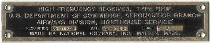
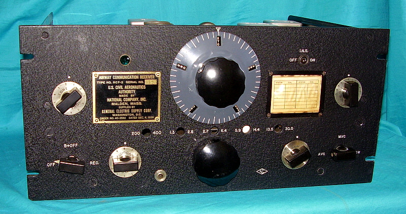
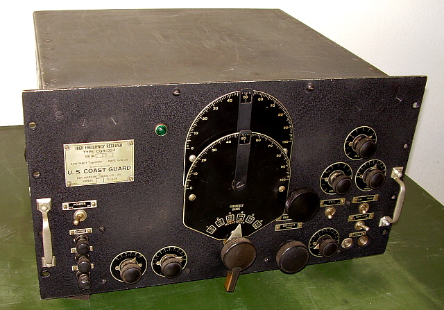
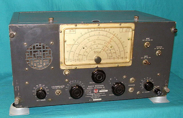
Serial Number and
Cabinet - The serial number of the AR-8516 shown is SN:5830. The
serial number incorporates the year of manufacture in the first two
digits, e.g., "58" is 1958 and the receiver number is "30." There is
also another tag mounted to the rear chassis that gives the month and
year of manufacture, in the case of SN:5830, the tag reads "JAN 1958."
The odd size panel height of 9.5" (rather than the standard 10.5") does
limit the receiver's installation into generic-type cabinets without an
obvious gap. Mounting the receiver in a rack will solve that issue. Of
course the proper RCA cabinet does fit the receiver panel correctly. As
stated in the manual, the AR-8516 was available as a table model
receiver with the cabinet (with the MM-555140-B installed) or it could
be ordered as a rack mount without cabinet (with the MM-555140-B as a
separate accessory.)
|
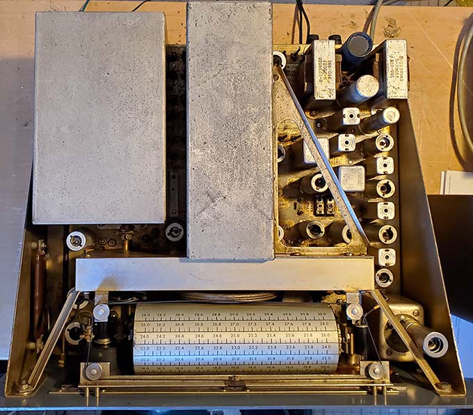
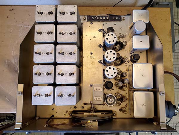
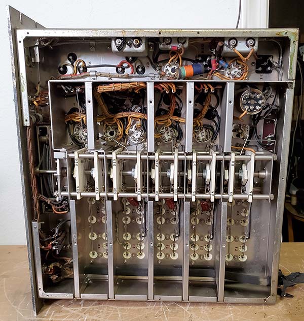
photo above: Top of the AR-8516
chassis |
>>>
Antenna Connections per the Manual - There are four antenna terminals
provided identified as A1, A2, GND and SHLD. The manual warns not to "ground" the SHLD
terminal. This is because in Bands 1-5, SHLD is connected as part of
the antenna input by essentially "shorting" the coax shield to the
center conductor of a coax feed line. This allows the receiver to have a
fairly efficient "T" antenna configuration in the LF and MW ranges. At Band 6, the band switch then connects SHLD to the
receiver chassis allowing the use of a resonant, coaxial fed antenna.
When using the typical unbalanced ham antenna, the center conductor of
the coax is connected to A1, then A2 is jumped to GND and then just the
shield of the coax is connected to SHLD. For the hook-up to work
correctly, the antenna shield can't be grounded anywhere and must only
be connected to the SHLD terminal. For hams the problem with this
hook-up is for 80M (Band 5) and 160M (Band 4) operation.
A More Practical Antenna
Hook-up - If you want to use a resonant unbalanced coaxial fed
antenna for much better reception on 80M or on 160M, then connect the coax shield to GND, A2 also
connects to GND and the coax center conductor to A1. Don't connect anything to SHLD.
If an antenna tuner and tuned dipole antenna combo is used with this
type of connection, then the tuner adjustments will "peak" normally. The
ANTENNA (trimmer) won't function on Bands 1 thru 5 because the antenna
signal is going to the Variable IF (the receiver is single
conversion in Bands 1-5.) |
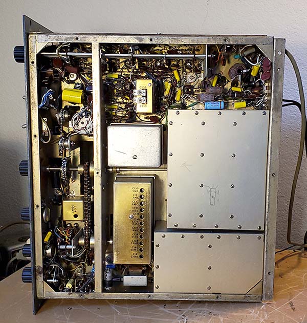
photo above: Underneath the AR-8516
chassis |
|
Building a Replica MM-555140-B |
|
The AR-8516 manual states that if a very low hum on the audio
output is desired or necessary then the receiver should be
operated on +115vdc. I decided to build a MM-555140-B since
finding an original would probably take a considerable amount of
time. Luckily, the AR-8516 manual has the schematic for the
MM-555140-B and there really aren't any unusual parts required
for its construction. In fact, everything to build my homebrew
version came from the various junk boxes I have around here.
I used a 150VA 1:1 Isolation Transformer as the main component.
The receiver requires about 80 watts for operation, so there's
lots of reserve capability in the transformer. Other components
were a full-wave bridge rectifier, two 40uf 300vdc electrolytic
capacitors, a 22K 2W CC resistor, a 25 ohm 50W WW resistor and a
6.5 ohm 60W WW resistor. The two large dissipation wire wound
resistors were made up of a parallel combo for the 6.5 ohm 60W
(15+15+75 ohms) and a parallel combo for the 25 ohm 50W (two 50
ohm 25W resistors.) >>>
|
|
 |
| >>> These dissipation values are much
higher than the original dissipation values called
out on the schematic but I found that those values
shown on the schematic did get very hot during
operation. This was probably because of the 122vac
line voltage I have. Actually, at the output of the
isolation transformer the voltage is 124vac, versus
the original MM-555140-B design for 115vac input.
Also, the 6.5 ohm value differed from original value
of 5 ohms but that again was due to the higher line
voltage versus the original 115vac design.
The + DC output has to be connected to the
receiver so +DC is routed through CR101 (the
half-wave rectifier in the receiver.) This would
correspond to the LINE (HOT) if the connection was
directly to the AC line. The
-DC corresponds to the AC NEUTRAL connection which is
internally connected to the power supply chassis
(transformer shield.) The B- inside the
receiver is isolated from chassis to allow -DC to be
connected to the power supply chassis The
chassis Ground of the receiver is connected just to
chassis of the DC supply. I used a three-wire power
cable so the power supply chassis and the receiver
chassis go to ground. >>>
|
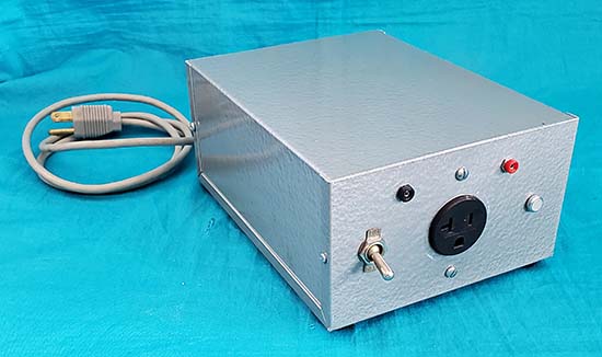 |
| >>> My version of the MM-555140-B was
installed into a 3.5" x 6" x 8" aluminum project
box. There is a standard single socket grounded AC
outlet on the front panel. Also, two pin jacks are
on the front panel that can be used for monitoring
the DC voltage to the receiver. Other power supply
features are an AC toggle switch and a 120vac neon
pilot lamp. The fuse holder is on the rear panel and
has a 2A SB fuse installed in the Line to primary.
When connected directly to my 122 volt AC line, the
DC voltage at the powered-up receiver is +115vdc +/-
1vac and the +115vdc remains very stable regardless
of the various functional adjustments made to the
receiver. DC voltage measured at the receiver at
initial power-up will start at about +112vdc, climb
to about +117vdc and then settle at +115vdc as the
receiver "warms-up" which takes about 30 seconds.
Hum is non-existent and the audio sounds very clean.
With no load, this power supply output voltage will
measure about +175vdc which isn't over the voltage
rating of the components used but the design output
voltage relies on an 80 watt load being connected
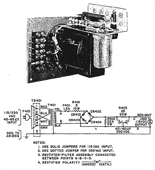
and that's where it operates correctly. The
upper-right photo shows my replica MM-555140-B. Shown to the left is the schematic of the MM-555140-B and also
the artwork of how the RMCA unit looked. |
|
|
AR-8516 SN:5830 Refurbishment |
| When acquired, SN:5830 did turn on and did receive some
signals, but it wasn't fully functional and really wasn't
performing at its design capabilities. Initial inspection found
five of the 18 tubes
were bad with two showing significant leakage (shorts.) The AF
gain pot was internally damaged and no amount of cleaning would
fix it since the carbon track was cracked in several places.
Luckily, I had a NOS 500K A-taper (audio taper) A-B pot to replace the bad original. De-Oxit
was used on the Bandwidth switch which helped it to function
correctly. The receiver was the rack-mount version so it didn't have
a cabinet and for some reason RMCA never offered a dust cover.
I guess they figured that the rack console would protect the
receiver chassis. However, decades of storage in a greasy
environment certainly had the chassis looking terrible. There
was a little minor corrosion but most of the contamination was
dirt, waxy-grease and probably tar-nicotine. The front panel had its share of
"battle-scars," "rack rash" and even some green paint
splatter. The knobs were just plain "grungy" with crud that
seemed waxy-like in all of the flutes and recesses. There was white residue
in the front panel screw slots implying
that the panel and knobs had been
rubbed-down with polish or wax in the distant past.
Thorough
cleaning required major disassembly. The knobs were soaked in
Dawn dish soap for two hours to loosen the waxy grunge after
which they were scrubbed with a short-bristle brush to
thoroughly clean. The knobs were then rubbed-down with a dry
cotton flannel cloth to slightly polish the surface finish. The
RCA meatball badge needed to be dismounted in order to remove
the pitting (600 grit AlOx paper,) cleaned with Glass Plus along
with a
wooden toothpick used to "dig-out" the wax in the
recesses between the letters and finally the badge was polished with Wenol's (British
equivalent of Semichrome.) The chrome handles had minor pitting
that was removed with Glass Plus and 600 grit AlOx paper
followed by polishing with Wenol's. The grunge on the chassis
was removed with WD-40 and an acid brush (with the bristles cut
short.) This was followed by Glass Plus to remove the WD-40
residue. In some stubborn places, isopropyl alcohol would cut
the grime better.
The plastic dial cover was removed, cleaned and polished. The meter
scale, the sector scale and the kilocycle/logging scale were
made of photosensitive phenolic that had darkened but careful
cleaning with Glass Plus brightened up the yellow-amber color
significantly without damaging the nomenclature. The dial scale
was a metalized over-lay applied to the drum. It cleaned up easily because the
material and the nomenclature were particularly durable and could be cleaned a bit more
aggressively than expected. I installed "matching" tube shields.
These were the standard flat aluminum type because the IERC-type
of heat-reducing tube shields are really only necessary when a receiver is going to be
operated 24/7. I matched the original paint on the front
panel (using 5 colors of Testor's model enamel - gray, black,
white, dark blue and brown) and touched up most of the "battle-scars."
The silver dial bezel was touched-up using thinned Testor's
silver paint. A
flat-razor blade was used to remove the green paint drops. The panel
mounting screws were cleaned and painted black before reinstallation.
After cleaning the tops of the two shield covers (RF-Sector
condenser and Variable IF condenser) they both look silver in
the photos. Actually, they appear slightly gold tint, though
much lighter than the chassis. The gold finish is called iridite
and it was a chemical bath that colored the sheet metal during
manufacture and before assembly.
| Disassembly issues not
mentioned in the manual: The BFO pointer is
dual set-screw mounted to the outer coaxial shaft of the vernier BFO
adjustment. To remove the front panel this pointer has
to be dismounted but you can't get at both set screws from the top. The
right side panel has to be removed to access the set screws to
dismount the pointer to allow front panel removal. All of the set
screws in the knobs and couplers are Bristol (spline) types. There
are four shaft bushings, two of which have "C" clips associated
with them (ANTENNA and TUNING.) The Antenna (trim) coupler set screws are easy to
access from the top. But, the TUNING shaft will require removal
of the "C" clip to be able to dismount the front panel. Also,
three of the bushings are standard size but one is much longer
than the others. The long bushing is used for the TUNING shaft for better support of the shaft which does have a large
counter-weight installed on it. The dial string assembly rail for the dial pointer
is mounted to the front panel. When the four screws are removed
this piece can then "flop around" and rub against and mar the
dial scale. Place several paper towels over the dial scale to
protect it during disassembly. Note that the PHONES jack is
isolated from the chassis and panel by two shouldered fiber insulating
washers. This jack should not be contacting the panel or
chassis (problems could result if using direct AC line operation.) Removal of the dial bezel requires removing the front
panel first, then plastic
dial cover piece is dismounted from the rear, then the bezel is dismounted from the
two retaining strips and then the two strips are dismounted from
the back of the panel. This assembly can't be installed or
removed if it is all put together, it has to be installed (or
removed) by dismounting each individual piece.
Sea Trials - Dec 12-15, 2020 -
After reassembly and completion of the DC power supply, I
operated the AR-8516 for a few days to get the "feel" of the
receiver. As acquired, this AR-8516 had already been
meticulously and carefully re-capped so I was pretty confident
that the receiver could operate for long time periods without
any serious problems. The receiver seemed to function pretty well but it was obvious
that some improvement should be possible.
The next day I found a very minor problem that had a significant
effect on reception. The jumper between A2
and GND had been a piece of solder (the lazy tech's jumper) and it
had broken at the A2 terminal. I replaced the solder with a TC
jumper. The signal reception level was greatly improved. I
tuned around 12.965mc and copied one of the Seoul, So. Korea coastal
beacon stations, HGW2. Also, a little lower in frequency and one of the
Chinese coastal beacon stations, XSQ was heard. The next morning, I tried
40M and some of the SSB signals were intensely strong. I tried
HGW2 on 12.965mc (should be at 12.915mc,...more on that problem
in the alignment section) and it was very strong. Fire Drake, the Chi-Comm
jamming signal on 9.85mc (it changes frequency all the time
since it's jamming Radio Taiwan which also changes frequency all
the time to avoid Fire Drake,) was very strong and showed
about 25db over 1uV on the carrier level meter. Trenton Military
Aviation Weather (Trenton, Ontario, Canada) on 15.031mc was
heard with a very strong signal. One other thing
noticed before, with the broken jumper, I couldn't seem to find
a good match with the antenna tuner. With a jumper installed,
now the tuner showed a very positive increase in reception when
the antenna match was "tuned." Also, the ANTENNA (trimmer) on
the receiver would "peak" now. It was also noted that
the best results on SSB or CW was to reduce the RF Gain and
advance the AF Gain which is typical of a receiver without a
product detector. If the RF gain is advanced too far it seems to
"mask" weaker CW signals with excessive background noise, again typical of a
standard diode detector. In AM Voice, the RF gain can be fully
advanced and the AVC allowed to control sensitivity. The RF
tracking is fairly close with the error at 15.000mc
being -6.0kc. The 500kc oscillator is off by about 400hz
and this affects 45kc IF and the 1.5kc-800-100hz
bandwidth performance (which barely worked) and the 500kc calibration marker
accuracy. Although performance seems pretty good, a full IF/RF
alignment will assure that the receiver is at its
design specs. |
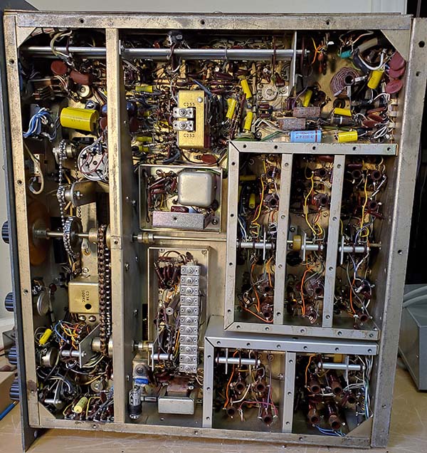
photo above: AR-8516 underneath with the
shield covers
removed from the Variable-IF bandswitch-coils, the RF
bandswitch-coils, the Crystal Oscillator bandswitch along with
the Xtal Osc trimmers and the Variable IF Mixer covers. |
|
| Return to the
Workbench - Dec 18, 2020 - It's pretty much standard procedure
to perform an initial refurbishment to get a set going, then use
it for a while to assess how it's going to work out and then plan what
else needs to be done to complete the rebuild. Although
performance was generally good and it seemed likely that the
AR-8516 could do a very good job as a station receiver there
were other mechanical and electronic things that had to be done
to enhance the receiver's functionality. Here's the list:
1. Mechanically aligned the slide rule dial to more accurately agree
with the kilocycle dial. Pre-alignment necessity.
2. Cleaned with DeOxit and a small paint brush all band switches.
RF sw, Vari-IF sw and Xtal Osc sw.
3. Cleaned rotor grounding contacts on both tuning condensers
with DeOxit and a brush. RF-Sector
and Vari-IF.
4. Cleaned (removed) dried Lubriplate grease from gear box gears
and made sure
backlash split gears were working. Lubriplate is designed for
sliding surfaces not for gears. It dries like concrete if it
isn't constantly in use and routinely cleaned off and reapplied.
This Lubriplate must have been decades old. Light oil
and an acid brush (bristles cut short) were used to remove the Lubriplate. Re-lubed split-gears and bushings with 10w
machine oil.
5. Cleaned and readjusted tuning shaft over-riding clutch. The clutch is a spring-loaded mechanism that had
been filled with Lubriplate - just what you need for a clutch -
it was locked in place!
Cleaned the Lubriplate off with light oil and a brush then washed the
mechanism with Isopropyl Alcohol to remove oil residue. Then
adjusted the clutch to "slip" at the dial end-stops.
6. All tube pins and sockets cleaned with DeOxit and a small
paint brush.
7. Adjustments for 2mc C to 3.9mc L Variable IF tracking had
GLPT lacquer "locking" them. Used lacquer thinner to remove the
GLPT so these two very important adjustments would be moveable.
Overall frequency readout accuracy depends on these two
adjustments. Pre-alignment necessity.
8. Replaced the 30" long power cord with a 72" long power cord.
AR-8516 Manual Alignment Procedure Critique
and Pre-Alignment Preparation - Normally,
pre-alignment preparation isn't necessary but the AR-8516 manual alignment
procedure is not written for "first timers" and assumes that the
alignment tech has been doing a lot of AR-8516 receivers before
and knows the locations of all of the components. I read through
the procedure before starting the alignment and found that I was constantly having to go to
chassis drawings and the schematic to physically locate key
connection points. For example, when aligning the 45kc IF,
the instructions indicate the VTVM should be connected to the
junction of R191 and R192 but no resistor values are mentioned.
There's no component location
drawing showing smaller parts (like resistors.) Small components
have to be located first on the schematic to find the values of these resistors so you
know what to look for under the chassis. You'll know generally
where to look from the schematic. First time is a hassle, that's
why the pre-alignment checkout.
To say the alignment procedure is
lacking details is an understatement. I found it necessary to
make lots and lots of pencil notations about important component values, test
point locations and even drawings of the IF transformer connections.
The 455kc IF transformers pin-outs are important because the
primaries or the secondaries or both have to be "loaded down"
with 10K resistors during alignment. Luckily, the IF transformer
pin-outs are vaguely mentioned in one of the schematic
notes,...no where else,...and even that information is
incomplete requiring a visual and continuity check to verify.
NOTE: IF
transformer pins viewed from
the bottom, green dot is pin 1, go clockwise for pins 2, 3 and 4.
Next, the RF signal generator
input for IF alignment is to the grid of V105 Mixer 1,...no problem,...except that the bottom of the V105 socket is located within a completely
shielded compartment (with more than thirty 4-40 screws mounting
the cover.) I used a seven-pin tube test extender
socket to input the signal to the V105 grid.
>>> |
|
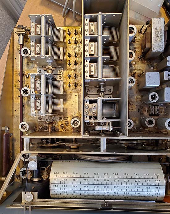
photo above:
Showing the RF/Mixer 1 tuning
condenser (left) and the Variable IF tuning condenser (center) with the shield covers removed.
Also, the gear box cover is removed showing the gear train. |
| >>> Another
complication in the IF and in the RF tracking alignment process is that the receiver has
to be on its side since there are adjustments both on top of and
underneath the chassis along with having to observe the front of
receiver for the dial readout. I had to use a 4"x6" hand mirror
to verify tuning dial readouts and sometimes the locations of
various trimmers to keep from bending over or leaning around the
side of the receiver for every adjustment. I guess I could have
turned the receiver around so the panel was in front but
then all of the difficult to see small chassis-located
adjustments would have to either require a mirror and
bending over and around the chassis or some other
uncomfortable contortions. I think that at
least a couple of days of reading, making notes,
visually locating the important component junctions and
getting all of the resistor loads, coupling caps and
alignment tools together will help to ease the alignment
process. |
|
| IF Alignment
- This starts with the 455kc fixed IF. The only unusual
requirement is the loading down of some of the IF transformers
primaries or secondaries
with 10K resistors. This pretty easy to accomplish if the 10K
resistors are on short flexible wires with small alligator clips
on the ends. The bottoms of the IF transformers are easy to
access for attaching the 10K loads. Two 10K loads are required
because T124 and T125 have both primary and secondary loaded
simultaneously when doing the adjustment. There is a trimmer
capacitor for the
mechanical filter that is adjusted for a relatively equal response between
the 6kc bandwidth and the 3kc MF bandwidth. The 455kc BFO is also
adjusted at this point in the procedure. The 45kc IF does require a signal
generator that will produce RF at that low of a frequency. I normally
use the HP 606B for alignments but its lower limit is 50kc. Luckily, I also
have an excellent General Radio Type 1001A RF generator that
will produce a RF signal as low as 5kc. For the 45kc IF, I had to
use the GR 1001A for the signal source. Four torriod type LCs
are adjusted with trimmer caps and one transformer L is
adjusted. The 45kc BFO is adjusted at this time.
The Variable IF is adjusted to track perfectly (or as close
as possible) from 2.0mc to 3.9mc. This is accomplished with
adjustable L and C and referenced to the kilocycle dial for
maximum accuracy.
This completes the IF alignment. |
RF Tracking -
The single conversion low frequency tuning is aligned first.
This requires adjusting six L and C adjustments per band for a
total of 30 adjustments. Only the 2-4mc single conversion band
(Band 5) can be aligned using the kilocycle dial. Bands 1-4 are
adjusted using the slide rule dial. After the tracking is adjusted on
Bands 1-5, then the 45kc wavetrap is adjusted at 80kc before proceeding
on to the double conversion RF tracking alignment. Bands 5-18
are double conversion and are aligned in four major divisions,
4-12mc, 12-20mc, 20-28mc and 28-30mc. Each Sector A, B, C and D
requires Crystal Oscillator peaking and RF-Mixer adjustments.
Seven crystals are utilized but six are doubled and used on harmonics to allow the
13 bands to operate. There are 23 adjustments plus peaking the
ANTENNA.
I couldn't get "to the kilocycle" accuracy using the
kilocycle dial. It's pretty close and does meet the
specification of dial accuracy of "within 10kc" which
seems to be pretty good (12-14mc is the exception - covered
in the next section below.) For frequencies below 4mc, dial accuracy spec is 0.5%
which is very easy to maintain.
The 500kc oscillator is adjusted using WWV and the beat note.
Since the BFO is on when in the 500kc CAL position, the BFO
should be set to zero so that only the 500kc oscillator and WWV
are heard when listening for the heterodyne zero beat.
There's also two adjustments for the AF feedback that are
adjusted for minimal "ringing" when in the narrow 100hz
bandwidth. Over 75 different adjustments are necessary for a complete
AR-8516 IF/RF alignment.
Errors and Suggestions - There are two obvious errors
or conflicting data in the manual's
alignment procedure. T121 is identified as a 12mc adjustment in
the manual's adjustment drawing. The receiver silk screening and
the manual written procedure are correct indicating that T121 is
for a 2.0mc adjustment. The second error is T115 is correctly
identified in the adjustment drawing as 220kc and the receiver
silk screening also shows the correct 220kc. The alignment
procedure "frequency table" incorrectly calls out 210kc for the
adjustment frequency. Some of the instructions are confusing in
the wording used and require further checking to confirm what
actually is required. The use of the IF 10K loads is a good
example of confusing language. As a matter of poor layout, the
manual has two chassis illustrations dividing the written
alignment instructions. My manual was in a binder and the pages
could be taken out as needed. If only a bound manual is
available then print copies of alignment instructions so the
book pages aren't worn out from flipping back and forth as the
alignment proceeds. |
| Post-Alignment
Performance and Issues - No doubt, the alignment
significantly improved sensitivity and certainly got the 45kc IF
working correctly along with the Bandwidth 1.5kc, 800hz and
100hz working very well. Listening on 20M quickly turned up a
ZS6 amateur from South
Africa. Trenton Military out of Ontario, Canada was easily
found at 15.035mc since their signal was very strong now and the
dial accuracy noticeably improved. WWV 15mc was about 1.5kc off frequency readout and WWV
10mc
was about 1kc off. However, WWV 5mc was off about 10kc (still
within the factory specs.) 40M hams required reducing the RF Gain down
to 4 for the very strong signals. 80M performance was quite good and the tracking on that
band (Band 5) was easily within the 0.5% spec. Just a
note,...there's no noticeable difference in using either a 3.2Z
or a 4.0Z speaker (as expected.) So, that was the good news,...but two problems were noted.
12-14mc Band Tracking
- For this problem I don't think there's any easy solution. The 12-14mc band tracking is off by about 45kc. Since all
other bands are very close in their tracking, I would think that
the Crystal Oscillator is the problem with the crystal being the
most likely suspect. The crystal is Y103, an 8.00mc crystal and
it is used twice, on 12-14mc and also on 28-30mc. A test on
29.0mc revealed an error of about 90kc which seems to confirm
that the crystal Y103 is the likely problem. From what I've
heard, there are virtually no companies that supply newly made crystals
anymore. I checked to see if the R-390A happened to use that
frequency crystal but it doesn't. In addition to finding an
8.00mc crystal there's also the physical access to the crystals
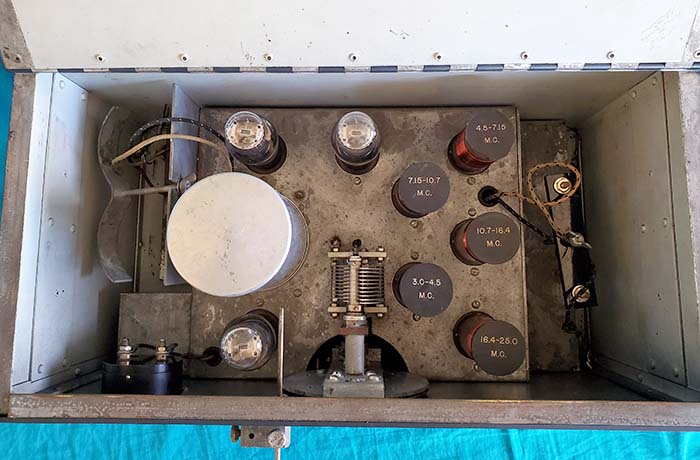
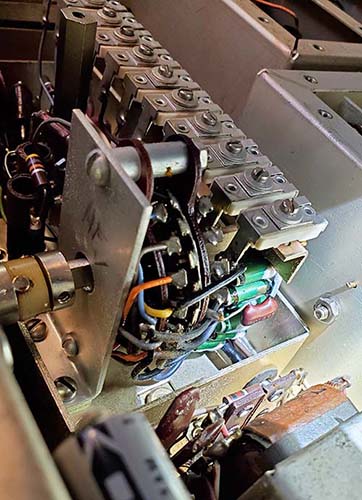
in the receiver which is beyond difficult. Looking at the photo
to the right, the crystals are soldered directly to the band
switch (they have a green coating on the metal housing.) I looks
like replacing a crystal requires extracting the entire Crystal
Oscillator as a unit. It's not a module but note in the photo
that the band switch shaft uses a slotted nylon Oldham-type
coupler which implies the Crystal Oscillator is removable. Since
performance on the 12-14mc band is excellent in all other areas,
I'll probably just have to accept that frequency readout on that band
(and on 28-30mc) is off. Even with a 45kc dial readout error,...at 12mc the
accuracy is still better than 0.5% (0.5% is 60kc at 12mc.)
Note: Used 8.000mc crystals are available from Alltechs in
California - seen on eBay - about $5 plus shipping.
200kc to 500kc Band
Sensitivity - The second issue was poor performance on the 200kc to 500kc band
(Band 2) and this was easily repaired. Low sensitivity on this
band was due to the misalignment of VFO at
220kc. I must have initially set the RF gen to
210kc as indicated in the manual alignment instructions
but actually had the receiver tuned at 220kc as indicated on the
receiver chassis silk screening (after all, I was looking at the receiver dial
in a mirror.) To correct the problem, obviously I realigned with the
receiver tuned to 220kc and the RF generator also tuned to
220kc. The other alignment adjustments (six adjustments, three
for 220kc and three for 500kc) were also peaked for Band 2 and
afterwards the sensitivity was quite good and the tracking was
excellent. In the evening, I set up the AR-8516 with the Pixel
Loop and tuned in several NDBs in the 300kc to 420kc part of the
spectrum. Best DX was LLD 352kc in Hawaii, several Canadian NDBs in
Manitoba and Saskatchewan along with several Mid-west 25W NDBs. With a wire antenna, signals were stronger but so was
the noise which is normal. Dial accuracy was good but the
dial's scaling is fairly vague.
Dec 23, 2020 |
 |
Performance as a Station
Receiver - I set up the AR-8516 with the Collins
32V-3 as a station to operate on 75M for the MRCG net and the
Vintage Military Radio Net. A Collins 270G-1 speaker was used as
the audio reproducer. The receiver doesn't have a remote standby
circuit so the front panel standby position of the operation
switch has to be used. Also, with the 32V-3 set up I use a
vacuum relay for the T-R operation for isolating the receiver
antenna input. Since 75M is tuned in on Band 5, the AR-8516 is
operating as a single conversion receiver and because the signal
routing is to the Variable IF, the ANTENNA (trimmer) isn't
functional. However, using a tuned antenna (~50Z for the transmitter) will
be a close match to the receiver input Z. Frequency readout is primarily on the
slide rule dial where the accuracy seems reasonable. Sensitivity
on 75M really isn't ever too much of a problem for just about
any receiver. Selectivity is much more important. 6kc bandwidth
can be used most of the time but it's nice to also have a 3kc
mechanical filter for tough QRM. I run the AR-8516 on +115vdc
and there's no hum at all on the audio output. It's very clean
sounding and voice articulation is reproduced quite well. The
result is easy-to-understand AM QSOs (most of the time.) The only
complaint would be the lack of remote standby that is actuated
with the PTT.
| For the most part, any shortwave transmissions
are easy to receive. CW also is reproduced nicely. SSB uses the
adjustable BFO position to select either USB or LSB and
selecting the "SSB" position
on the operation switch does provide a slight increase in BFO
injection. Stability in the CW or SSB mode is excellent. Using
the narrow Bandwidth will depend on how well the receiver is
aligned. When first tested, this AR-8516 hardly functioned in
the narrow Bandwidth positions since alignment of the 45kc is
crucial for these functions. After alignment, the narrow
Bandwidth selections function great and are a benefit for CW in
crowded band conditions. Also, the narrow bandwidth selections
utilize the 3.1kc mechanical filter at 455kc and then use the
45kc IF to provide 1.5kc, 800hz and 100hz bandwidths. When
properly aligned, the AR-8516 provides excellent selectivity
options. Update: May 2021
- I built a wooden cabinet for the AR-8516. Nothing
fancy. In fact, I built it out of "used plywood" and
from some of the edges, I guess that's pretty apparent.
But, it is square and it does a good job for having a
place for the loudspeaker and other accessories to set.
I painted the cabinet gray and I designed it to conform
to the dimensions of the front panel and the full depth
of the chassis. Overall, the gray paint finish helps to
disguise the fact that the cabinet is made out of wood
(well,...maybe a little, especially in average room
light,...with stuff piled on top.) I think it's a nice
improvement to the AR-8516 "looks" overall and certainly
provides more bench space than the open chassis did.
I've been
using the AR-8516 paired with an ART-13A transmitter and
have found it to be an excellent station receiver with
very nice audio and excellent selectivity. The lack of "remote standby"
can be compensated for by using the front
panel standby switch. With the
generous band and frequency over-lapping, the military radio nets - all being
at the upper end of 75M - can actually be tuned in on Band 6
(4-6mc) to take advantage of the double conversion.
Although not shown in the photo, I'm still using the
Collins 270G-1 loudspeaker with this receiver. |
 |
|
|