Radio Boulevard
Western Historic Radio Museum


NATIONAL  COMPANY,  INC.

 HRO  - COMMUNICATION RECEIVERS - "The Cream of the Crop"

   PART 2

Serial Numbering Analysis  ~  Dating by Serial Number 

   Engineering Changes  ~  HRO Coil Details, PS Details, Accessory Details 

 
by:  Henry Rogers WA7YBS

PART 2
 

HRO Serial Numbering System

The Charles Fisher Survey - At first glance, National's serial numbering system seems confusing. There was a rumor that the serial number system was designed to hide the actual production quantity of receivers being built but this seems unlikely. Several years ago, Charles Fisher performed a survey of about 70 early HRO receivers to determine the serial numbering method that National used. His article was published in the AWA OTB in 1989 (it is also currently on the web - link provided below.) The Fisher article contains a wealth of information for the HRO enthusiast.

The Production Runs - Fisher's survey determined that National used a combination letter prefix and number suffix for their serial numbers on the early HRO line, e.g. D-12 or G-115. Each production run of receivers were given a new letter prefix and the numbers are then sequentially assigned. The first HRO run begins with prefix "D" and was probably only about 100 units. Run "E" and most subsequent runs are made up of about 250 units. Sometimes runs overlapped each other. Letters "O" and "I" may not have been used due to their similarity to numerals. By about mid-1938, the letter prefix had gotten to the end of the alphabet and the serial numbers were changed to number prefix with a letter suffix but numbers up to 500 were used, e.g. 123-F or 434-H. By the beginning of WWII, this type of serializing had reached the "L" suffix and was halted. Fisher wrote that during WWII, the numbering again changed - this time back to the letter prefix but using number suffixes higher than 250 with the exception of prefixes A, B and C which, since they were not part of the original serial numbering sequence, used numbers beginning with 1. Also, during WWII the letters "O" and "I" were used in the serial number combinations. There are many exceptions and many variations to the WWII serial numbering, though. Read the section "More on WWII Serial Numbers."

Total production quantity from 1935 up to about the beginning of 1941 was around 8000 to 9000 receivers. Around 5500 to 6000 receivers comprise the letter prefix serial numbers with the remaining 3000 or so using the letter suffix serial numbers.

Western Historic Radio Museum Serial Number Log - WHRM started an HRO serial number log for ALL tube-type HRO receivers in 2007. Our serial number logs for other communications receivers have been very successful in determining production levels and other interesting manufacturing data. One of the first discoveries for the HRO receivers was the change of format for serial numbers on the HRO-5A1 receivers that continued on through the HRO-60 receivers. Additional serial number reporting has revealed the dual prefix letters used during WWII. Please keep reporting your HRO receiver serial numbers. As seen, important information can be found when enough numbers are gathered. Use the e-mail link below in "Dating Early HRO Receivers by Serial Numbers."

More on WWII Serial Numbers - After receiving several reported HRO serial numbers from enthusiasts, it has become apparent that several systems of serial numbering were used during WWII. Most of what Charles Fisher found is true but there are many exceptions turning up as more serial numbers are reported.

The HRO-5/W receivers seem to re-use older serial number sequences, note that the reported HRO-W receivers are all serialized with the "K" prefix. The serial numbers used for the HRO-W "K" run were certainly duplicates of earlier issues from the 1935-36 run. The same is true with HRO-5 sn J-39. Apparently, National believed that the HRO-5/W was a different receiver, or at least different enough that it couldn't possibly be confused with the earlier HRO Senior - after all, the 5/Ws used octal tubes.

Additionally, there have been several HRO-M receivers reported that were serialized with a two-letter prefix followed by up to three numerals,... AP-461, PC-67 and PP-988, for example (there are more.) It's possible that this double prefix was to avoid confusion with early HRO receivers built with the same number but with a single prefix, however PP-988 is much higher of a number than the earlier single P prefixes used so there might be another meaning to the double prefix. The two-letter prefix AP-461 is an exception since the single A prefixes were issued during WWII and had no special limitations since there weren't earlier "A" prefixes issued. One note is that nearly all two-letter prefix HROs are located outside the USA. Possibly, the two-letter prefix identifies production runs that were specifically for Lend-Lease sales. Additionally, it can be noted that only one "P" prefix serial number has been reported for an HRO Senior and only one HRO Junior has been reported with a "P" prefix number. This leads one to speculate that perhaps the "P" run in 1936 was a relatively small quantity allowing WWII use of the "P" prefix with numbers as low as 150 or so.

Certainly, WWII was a hectic time for National HRO production and variations in their serialization of receivers should be expected. Keeping the serial numbering format and sequences in order was probably very low on the "list of priorities" at National during WWII. Even post-war serializing was not consistent and variations should be expected until around mid-1946.

Post-WWII HRO Serial Numbering System - With the mid-1946 HRO-5A1, a completely different method of numbering was used consisting of two groups of numbers with no letters. The format is usually three numbers, a space followed by four numbers, e.g. 184 1054. This serial numbering format was used from the HRO-5A1 up through the HRO-60. It appears that the first three digits identify a production run and the four digits identify the particular receiver in that run. Note the reported HRO-5A1, HRO-50 and HRO-60 receivers and that the production run digits progress higher from the HRO-5A1 (184) to the HRO-60 receivers (345, 366, 393.) Also, note that all of the later receiver identification numbers consist of a zero followed by three digits (indicating that production run levels are seldom more than a few hundred receivers.)

Dating HRO Receivers by Serial Numbers

Charles Fisher's Survey

Charles Fisher compiled a list of serial numbers from 70 early HRO receivers during his survey for the AWA's OTB article. By using the serial numbers compared to the evolution of the example it was possible to extrapolate a logical sequence of serial numbers. To the right is Fisher's table of serial number prefixes and suffixes, which identify the specific production runs, tied to probable build-dates. Since the survey was only concerned with early HRO receivers the cut-off for entry into the survey was that the receiver had to use the plug-in crystal on top of the crystal filter unit. The dates only go up to the beginning of production of the HRO-M receiver which was the National designation for HRO receivers produced for WWII.

Charles Fisher didn't publish the complete serial numbers of the 70 HRO receivers reported in his survey. He reports quantity per production run letters only. Here is a link to the complete Charles Fisher article: FISHER: Dating the National HRO 


WHRM's National HRO Serial Number Log   

I have started a serial number log here for ALL tube-type National HRO receivers. The log will be divided up for each model of HRO and will include all tube-type models from the first HRO receivers up to the HRO-60. This log will eventually be an on-line source for dating any of the HRO receivers. The more serial numbers sent in, the more accurate the data will be. If you have several HRO receivers, be sure to designate which serial number goes with which model receiver.

To Send HRO serial numbers:  WHRM HRO SERIAL NUMBER LOG     


Serial Number Locations

On HRO receivers from 1935 to early WWII versions, the serial number is stamped next to the Antenna-Ground input terminals insulator block, between the insulator block and the left edge of the chassis. This allowed the serial number to be easily viewed by looking through the square hole for the antenna input located on the left side of the receiver. Late in WWII, the HRO-M, HRO-5 and HRO-W had the serial numbers stamped to the left side of the audio output tube between the tube socket, the meter zero pot and the left edge of the chassis. This required lifting the receiver's lid to see the serial number. Early post-WWII receivers use the same location next to the audio output tube. With the introduction of the HRO-5A1 and the new serial numbering system, the location was moved to the right side top edge of the chassis mid-way back. This location was used up through the HRO-60 production.


Pre-WWII HRO Production Runs and Build Dates
 

 SN / Letter Prefix                     Probable Build Dates                                     

             D, E                         January-March 1935                                         

             F, G                           April-July 1935                     

             H                              August-September 1935

             J                              October-November 1935

             K                           December 1935-January 1936

              L                              February-March 1936

             M                                  April-May 1936

              N                                     June-July 1936

           P, Q, R                       August 1936 - February 1937

           S, T, U                         March-September 1937

           V, W, X                       October 1937-April 1938

             Y, Z                              May -October 1938

       Letter Suffix  A                     Nov-Dec 1938

       Letter Suffix  B - L           Jan 1939 -  late-1941


 HRO Serial Number Log (Pre-war and Wartime)

HRO:  D-17, D-21, D-34, D-35, D-38(R), D-46, D-49 (R), D-52, D-65 (R), D-72, D-76, E-18, E-50, E-55, E-58, E-68,
E-76, E-159, E-167, E-169, E-170, E-172, E-178, F-09, F-16(R), F-51, F-58, F-146, G-63, G-113(Nat'lMod), G-126, G-193, G-217, G-235, H-7, H-20, H-103, H-121, H-146,

HRO Senior:  J-60, J-123(R), J-146, K-38, K-83(R), K-91(R-Grey Panel), K-104, L-36, L-73(R), L-114, L-175(R),
 L-178(mod'd), L-184, M-108, M-167(R), M-183, N-25, N-29, N-79, N-130, N-146, P-16, P-35, P-98, R-54, R-207, S-64, S-208, T-87, T-239, V-22, V-27 (Orig. Gray Wrinkle paint), V-35(scrapUSN), V-77, V-214, X-61, X-204, Y-53, 129-A, 7-C, 233-C, 231-D(CollinsSAF) 30-F, 197-F, 164-G, 170-H, 182-H, 41-K (RCAF rcvr), 463-K, 169-L(R), 434-L(R)

HRO Junior:  J-16, J-125, J-248(Am.Airlines Mod'd), L-58(R), N-224, P-116, O-250(R-WWII Mil.), Y-217, 326-K, 103-L,

HRO-M, HRO-MX, Canadian HRO:  A-67, A-69, A-117, A-181, AP-195, AP-461, AP-361(Blue-CAN),
AP-634(RCCS), AP-675(M), AP-1001, B-72, B-631(MX), C-262(MX), C-392(MX), C-638, C-737(MX), C-896(MX),
 D-656(MX), D-706(MX), E-239(MX), F-180(SC R-106), F-260(MX), F-363(MX), F-443, H-420, J-942(R-106), L-427(M), L-481, M-243, M-326, M-400, O-4, P-161, P-240, P-377, P-554, P-861(R106), PC-67, PC-83, PC-103, PI-I-742, PP-128, PP-229(R), PP-569, PP-808, PP-988, PP-1133, 0605 (no letter prefix, RCCS version), 32-F, 333-L (Blue-CAN), 99-W(Blue-CAN), 197-L(RCCS), 227(R-460/RC-105), 486(R-106),

HRO-5, HRO-W:  J-39, J-116(5), J-431, J-607, J-879, K-127(W-SC#85), K-184(W), K-461(W,R), K-650(W),
 K-724(W-SC#192)

U.S.N, - RAS, RAW, RBJ, etc:  119(RAS), 310(RAS-2)          

(R) = Rack Mount, otherwise receiver is a table version                    (Nat'lMod) = Receiver modified at National 
(R106) = British designation, (R-106) = Signal Corps designation       (scrap) = Receiver parted out
(W) = Signal Corps version, receiver is same as HRO-5                   (USN) = Receiver used by Navy  
(mod'd) = Receiver severely ham modified                                        (RC-105) = USCG HRO Sr. 
(Blue-CAN) = Canadian end-users, with blue panel & cabinet (if table,) may also apply for RCAF receivers 
(CollinsSAF) = French Importer Paris, special front panel label
(RCCS) = Royal Canadian Corps of Signals special mods to HRO-M                    

HRO Serial Number Log (Post-war)


HRO-5A, HRO-5A1:
K-557(TA), K-611(TA), K-785 (RA1), L-39(TA1), L-56(TA1), L-80(TA1),
184 0005(TA1), 184 0008(TA1), 184 0009(RA1/HRO-5C), 184 0122 (RA1), 184 0180(TA1),
184 0205, 184 0328(TA1), 184 0346(TA1), 184 513(TA1), 184 0781(TA1), 184 0805(TA1),
184 0833(TA1), 184 0883(RA1), 184 1001(RA1), 184 1052(TA1), 184 1054(TA1), 189 0081(TA1),

HRO-6: 184 0297, 184 0697

HRO-7:  189 0131, 189 0396(T,BWF), 196 0397, 196 0546, 205 0143, 232 0094, 232 0146, 232 0391, 232 0973,

HRO-50, HRO-50-1:  280 0194(T), 280 0224(R), 280 0455(T), 293 0036(T), 293 0213(T), 293 1067(T), 311 0101(T-1), 311 0136(R), 311 0186(T-1), 311 0324(R-1), 311 0378(T-1), 311 0506(T-1), 311 0909 (R-460/UR) 327 0183(T-1), 327 0337(T-1),

HRO-60:   345 0127(T), 345 0154(T), 345 0165(R), 345 0232(T), 345 0958(R), 366 0591(T), 366 0800(T), 393 0049(T), 393 0177(T), 393 0255(R), 425 0013(T), 425 0234(T), 459 0033(T), 505 0173(T)


(R) = Rack Mount   (T)= Table Version  (T-1)= HRO-50-1  (TA1)= HRO-5TA1 (RA1)=HRO-5RA1 (BWF)=Black Wrinkle Finish


NOTE: From late HRO-5A1 to HRO-60 all SNs are seven digits. First three are the production run followed by a space with the last four digits being the serial number of the specific receiver.


Current Owners of First and Second Production Run HRO Receivers

Recently, Jim Hanlon (W8KGI) wrote an interesting article published in Electric Radio (Oct.2014) that listed some of the original owners of the first 100 HRO receivers. I thought it might be interesting to list the current owners of the HROs from the first two production runs. I included the second production run receivers because they are almost identical in most respects to the first run receivers. Also, including the second run increases the "pool" to just under 300 receivers. I've listed the reported serial numbers below and have listed the owners (by their ham call, if they have one) that I have kept track of. If you're the owner of one of the HROs listed below and you're not shown as the current owner, please let me know (again) and I'll get your ham call logged with your receiver. If you own a "D" or "E" prefix SN HRO receiver that's not listed below, please report your SN and I'll get it listed above in the regular HRO SN log and also below.
Thanks, Henry Rogers WA7YBS   e-mail info to: 
WHRM HRO D & E SERIAL NUMBER LOG

First Production Run

D-17 - W3NLB
D-21 - E. Bourgougnon (France)
D-34 - WA1KBQ
D-35 - KN4R
D-38 - W7CG(SK), now KA7FIP & K7DVK
D-46 - KE7RD
D-49 - W9AC
D-52 - W4BZ
D-65 - WA7YBS
D-72 - W3NA
D-76 - on eBay - Dec 2018

Second Production Run

E-18 - W4BZ
E-50 - WA7YBS                      
E-55 -  W4BZ
E-58 - AB3L 
E-68 - WØLQJ                                    
E-76 -  W9AC                                     
E-159 - K6GLH
E-167 - N6FEG
E-169 - W6DJX
E-172 - W3PR
E-178 -


HRO Production and Engineering Changes from 1935 to 1941

1935 - Runs D, E, F, G & H

White "pearlized" push-button S-meter switch (D,E)   -  S-meter switch changed to black push-pull switch (F-on) - The push button switch was noisy in operation and "popped" through the audio when released. Additionally, the push button required the operator to hold the button down with one hand and tune in the station with the other hand - inconvenient at best.

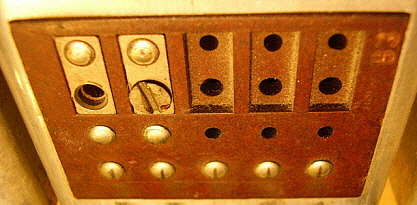
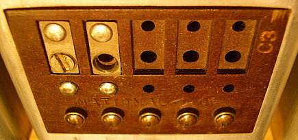
White coil graphs (D,E,early F)   -    Coil graphs changed to black (mid F-on) - black graphs did not show moisture stains or possibly glue stains. Coil shield boxes on 1RF, 2RF and Mixer have only one access hole for alignment. LO shield box has two holes. This is for runs D and E. From F-on two holes are found on all Coil shield boxes. Additionally, runs D and E will have very small contact buttons on each of the coil insulators. These buttons are the connections from the coil set to the receiver. F-on these contact buttons become a two-piece assembly that is larger and taller. Also, runs D and E have coil insulators with no embossed nomenclature. Coil insulators on runs F-on have "National Co." and pin numbers embossed into insulator. Paint on coil set panels will match the receiver panel. Crackle finish (leatherette finish) will be found on rack mount coil sets and wrinkle finish will be found on table model coil sets.

Metal case non-illuminated S-meter with 0-5 scale (D-H) - 0-5 scale conformed to early QSA signal reporting method. 5 is at half-scale with nothing indicated on the arc of the scale above 5 (except as noted below.) -  All E production run receivers seem to have the meter cases with a smooth "rounded" flange. The earlier D-runs and post-E runs have meters that have a slight indentation along the rim of the flange. The difference is subtle. Possibly component cost resulted in the use of a different style meters during the early production runs.     METER SCALES - D-run S-meters have a pinkish-gray colored NC diamond logo with white "NC" letters, "PLUS" is printed in black and located in the arc >5. This same scale was also used on most of the E-run but very late E-run meters may have the later "F-run type" 0-5 scale. F-run meters, the NC diamond is reddish-orange with black "NC" and the "PLUS" is no longer printed >5. For examples of each meter scale see photo C in "Features Found on Earliest HRO Receivers" in a section above. For F-run to H-run type of scale see photo of HRO SN: F-16 in the HRO section above.

Round IF cans (D-P) - hex adjustments of air trimmers required special tool (insulated .25" hex screw head driver) - these are actually "slotted" screw heads that have been soldered over so only a hex adjustment tool can be used. An early Millen article on the HRO in "Short Wave Craft" issue of March 1935 shows the HRO chassis. Interestingly, chassis photo also shows the BFO can with an adjustment knob on the top. Fisher reports this BFO knob is also seen in a rear page photo in first instruction manual. Doubtful this knob was on any production units.

Black chassis (D-L) - conformed with the SW-3 and FB-7 chassis paint use

Tuning condenser insulators are stamped out of sheet insulating material leaving rough edges used on D and E runs only. With run F, the tuning condenser insulators are molded bakelite with smooth edges and have a embossed spacer where it meets the metal spacers (F-on) -  the bakelite insulators were less hygroscopic than former material which tended to warp in excessively humid areas

"NC" in red background on the dial pointer mounting screw (D, E-partial, F-partial)   -  Dial pointer mounting screw changed to plain nickel-plated "raised diamond" (G-on) - cost reduction. Fisher indicates that the "raised diamond" first appears on the E runs but is intermixed with earlier "NC" pointer until G run. The "NC" pointer emblem mounting screw was also used earlier on the SW-5 escutcheon. Many D and E run HRO receivers no longer have the original "NC" mounting screw because this part was very fragile and tended to break after a few times of removing the upper rail (which was necessary for coil set alignment.) The replacement was naturally the later version part, the "raised diamond" mounting screw-nut assembly.

No pilot lamp (D,E)   -   Pilot lamp incorporated (F-on) - there was no visual "power on" indicator until the pilot lamp was installed

No external standby switch terminals (D-E-early F)   -   Stand-by terminals marked "BSW" (B+ SWitch) added to rear of chassis (mid F-on) - allowed for remote control of B+, typically with a T-R switch that controlled the transmitter and receiver operation. Initially, the "BSW" terminals allowed a parallel connection with the B+ "ON-OFF" panel switch. This required the receiver be operated with B+ "OFF" on the panel switch and then allowed the remote switch to control receiver operation. The parallel connection is shown in the 1936 manual. By 1937, the "BSW" terminals were then connected in series with the B+ "ON-OFF" switch. This allowed the B+ panel switch to remain in the "ON" position and still allow remote switching. Also, the panel B+ switch was functional as far as being able to remove (only) the B+ independent of the remote switch in the "receive" position. This function would be necessary when changing coils. If the 1937 or later HRO receiver was going to be operated without a remote T-R switch, as in a "receive only" installation, then a jumper had to be installed across the "BSW" terminals to allow B+ to be routed to the B+ "ON-OFF" panel switch and allow receiver operation using the panel B+ switch.

White ceramic resistors with hand written values in blue ink (D-E) - Black ink-stamped values  (F-~R)  - both types of resistors were built at National. By run R resistors are purchased from Centralab.     

Tubular paper dielectric capacitors used in the first few production runs appear to be Micamold manufacture. This is a departure from the Sprague capacitors that National used in the AGS and FB-7 receivers. It has been reported that HRO J-123 (from early 1936) has all original Aerovox capacitors installed. Also, it's been reported that HRO N-146 was equipped with paper capacitors that only had the values, a run number and a foil indicator band on each capacitor. By production run-V (as seen in V-35,) National had returned to using all Sprague manufacture capacitors (change probably happened much earlier.) A close examination of the under chassis photo used in the 1935 and 1936 manuals will show that the paper capacitors are Micamold manufacture. Note that the cathode bypass electrolytics are of Aerovox manufacture, however. It's likely that National was watching expenses due to the Depression and shopping around for the best prices from various capacitor companies.

German Silver plated PW-D micrometer dial (D-H) - the Index and Number dials are cast pot metal made by Doehler Co. Very fine castings on early dials since they were to be German Silver plated. Later castings used for Lacquer painted dial (J-on) are poorer finish casting since the paint acted as a "filler" and the final finish was smooth and even. Since white paint was used for the index lines, the engraved index lines are somewhat wider (to accommodate the paint fill) when compared to the plated dial (except for early painted dials which still have the narrow index lines - probably up to the end of 1936.) 

Antenna-Ground connector uses "push" connectors with insulated button on top, fiber insulated mount (D-~ suffix B) - buttons are always missing indicating that these pieces tended to break easily. First production run units (D-run) will have the A-G terminal insulator strip mounted further into the chassis leaving about a 0.5" space for the serial number. With run-E, the A-G terminal insulator is mounted much closer to the chassis edge leaving only about 0.25" for the serial number. Also, D-run receivers will have the ground lug and wire mounted with a screw and nut centrally in the blank area adjacent to the 1RF coil terminal block. Run E units and later have the ground lug and wire attached to the mounting screw for the audio output tube shield because holes for optional audio output transformer mounting. From run-E on, five 0.25" holes and four 0.125" holes are stamped into the chassis in this formerly "blank" area to allow mounting an audio output transformer, if requested. This was commonly requested by military users and some commercial users. The five larger holes are for the transformer leads and the four smaller holes were to mount the transformer.

S-meter potentiometer is located closer to the meter in the blank area of the chassis near the 1RF coil terminal insulator on first production run (D.) Pot moved to between the Ant.-Gnd. terminal insulator and the Audio Output tube shield for run-E on. Pot location moved to allow for mounting holes for optional audio output transformer.

The schematic and under chassis photo in early manuals shows the First Audio Amplifier tube grid biasing is accomplished with a 500K resistor directly to chassis. The audio is routed from through a coupling capacitor to the end of the Audio Gain control with the arm connected directly to the AF amp grid. Later manuals and under chassis photos show the biasing through the 500K is routed to the 2B7 cathode. The Audio Gain control is coupled to the 2B7 grid through a capacitor. This change was probably to reduce the noise created while adjusting the audio gain level on the early receivers. But, just how early this change was incorporated into production is unknown. The change appears to be an original installation in HRO F-16 (April 1935.) I found a good photo of D-76 under chassis appearance and it conforms to the early schematic. This indicates that run-D and probably most of run-E will match the early schematic. By run-F, it's likely that the 2B7 is wired like the later schematic. National apparently didn't think the change was very important since the schematic wasn't changed in the manuals until after run-N (mid-1936) and the under-chassis photo wasn't changed until after run-suffix K (1939.)

Around run-H, the value of the 2nd IF Amplifier cathode resistor (R-9) changed from 300 ohms to approximately 1500 ohms. The value of R-9 was selected during test. Later manuals specify the value range from 1000 ohms to 5000 ohms. Also, by run-H, the value of the S-meter bridge resistors (R-11 and R-30) changed from 2000 ohms to values selected during test. Later manuals specify the value range from 250 ohms to 2500 ohms for R-11 and 0 ohms to 2000 ohms for R-30.

Value of C7 erroneously shown in the parts list from the very first manual. Value shown as .1uf  200wvdc but actually a .01uf 400wvdc capacitor was always installed. Close examination of the under chassis photos used in manuals in 1935 and 1936 show that C7 was a .01uf 400wvdc cap (the value can be read in the photo) and that the error was in the parts list. Additionally, C-28 was sometimes listed as a .01uf 600wvdc tubular capacitor but nearly all receivers had a .01uf 400wvdc tubular capacitor installed.

National Co. decal added underneath the cabinet lid by G production run.

Cabinet has small 0.25" holes in the rear panel for ventilation - enlarged holes and louvers on the sides appear with J production run. Rack mount cabinets generally don't have the raised finger lift on the top lid. This was to allow clearance when mounting the receiver into a rack when another piece of equipment was mounted directly over the receiver.

Small skirted knobs have short round boss on lower part of square bakelite portion of knob grip (D-~N) - The later knob grips have a round boss that is much taller (after ~N.)  There are also changes to the skirt in thickness and depth of engraved nomenclature. Earlier skirts tend to be thinner with shallow engraving. Early short boss knobs had a tendency of cracking and that might have been the reason that National went to the taller boss knobs.

Early Crystal Filter shafts support bearing is screw-mounted to inside of the front panel (D-~F.) Later shaft supports are screw-mounted to Crystal Filter assembly (F-on.) 

TC wire connection from Crystal Filter housing to Tuning Condenser frame added for better ground connection of the tuning condenser shields (~G-on.) Appears sporadically on earlier production.

Early ceramic (Isolantite) sockets, National type XC, used for front-end and 2nd detector tubes (five sockets total.)  (D-~V)  XC sockets are replaced with later version National sockets (Steatite, ceramic similar to Isolantite,) type CIR, that have a metal mounting flange (by ~V, probably earlier.)

1936 - Runs J, K, L ,M, N, P & Q

S-meter scale changed to 0-9 (J-on) - the scale change was to follow amateur adoption of the RST method of signal reporting - scale remains white with black numbers, red NC diamond with black "NC"

S-meter case changed to a bakelite housing (J-on) - it was possible for B+ to appear on the metal zero adjusting screw, new design corrected this. At first this meter version was not illuminated. Illumination added to meters by mid-1937 which corresponds to the addition of this type of meter to the NC-101X receiver.

German Silver plated PW-D micrometer dial changed to "black" lacquer (J-on) - cost reduction because the paint can act as a filler. This allowed Doehler to use castings that were not as "fine" of a finish as was required for the German Silver plating. The new painted PW-D also conforms with introduction of NC-100 models (although the NC-100 dials are painted bluish-gray on the Index dial and red on the Number dial.) NC-100X receivers used the same bluish-gray Index dial but the Number dial was black instead of red. Airway Receivers used gray Index dials with black Number dials. NC-101X generally uses the same "black" dial as the HRO (although early versions may have the same PW-D as the NC-100X.) Paint color varies on HRO receiver's PW-D and generally is found in colors that vary from dark gun metal gray up to dark bronze. There is no chronology to the variability of the paint shadings so it's possible to find PW-D dials of any combination fitted to almost any National receiver. Perhaps this was intermixed stock or due to specific parts shortages - or maybe the subtle paint shading wasn't important to National. Unfortunately, it's very difficult to confirm authenticity of any PW-D fitted to any HRO since the PW-D could have been changed at anytime by contemporary collectors. One more note on PW-D paint,...it seems likely that Doehler supplied National with just the PW-D castings and the actual painting of the PW-D was done at National. This would allow National to use whatever colors they needed without requiring Doehler to stock various paints and keep track of what orders required what paint. Much easier if National handled all of the painting of the PW-D parts. This would then account for the many variations found in the PW-D color tints.

Holes top rear of cabinet enlarged (J-on) - better ventilation of cabinet.

Louvers added to side of cabinet (J-on) - better ventilation of cabinet

Chassis paint changed to gray (K-on) - probable cost reduction by conforming with NC-100 and newer models

HRO Junior introduction announced in February 1936, however earliest reported Junior is J-125 from Oct-Nov 1935 - The Junior is standard HRO construction but without Crystal Filter, S-meter or S-meter Switch. Only one coil set is included with the receiver although there are four specific coil sets for the Junior. All Junior coil sets do not "band spread" (general coverage only,) have only one frequency graph and are identified with a "J" prefix. Specific Junior coil sets are JD, JC, JB and JA. After the HRO Junior is introduced the standard HRO is referred to as "HRO Senior." National may have based the Junior on some versions of the HRO that they supplied to American Airlines. One of these AA-HRO receivers has turned up with a serial number prefix of "J" (sn J-245) which would be pre-date the February 1936 introduction date of the "civilian" HRO Junior. The story of James Millen coming up with the Junior because of ham requests for a less-expensive model HRO is from a QST open-letter by Millen explaining the origin of the Junior but Millen doesn't mention the American Airlines version in the letter.

Dec.1936 issue of QST, back inside cover National advertises a Gray "Leatherette" Finish HRO in a table rack MRR and speaker-coil storage panel SPC. Ad runs several times in 1937 and 1938. National would do special orders requiring special paint colors. RCAF Blue is probably the most often seen version. HRO V-27 is a 1937 table version with original gray wrinkle panel and cabinet. Also, HRO K-91, a rack mount version, has a smooth gray painted panel along with the same paint for the coil set panels. Other color variations are certainly possible since National did their own painting.

NOTE ON VINTAGE WRINKLE FINISH PAINT:  Why is the wrinkle is only on the outside of the cabinet? Originally, wrinkle finish paint was a two-part process that first used a nitrocellulose lacquer base coat that was in the color the cabinet was going to be - black, for instance. The base coat was allowed to dry for several minutes to several hours. The length of time the base coat dries will determine the intensity of the wrinkle (longer drying time results in finer wrinkles.) Then the cabinet was painted with a catalyst that was usually tinted the base color. The amount of catalyst sprayed also determines the intensity of the wrinkle. The cabinet was then put in an oven as the wrinkle effect had to be heat-induced. After removal from the oven and cooling down, the wrinkle was set. Sometimes an additional coat of base lacquer was applied over the wrinkle to protect the final finish. So, that is why today when looking at an original wrinkle finish paint job, the outside of the cabinet has the wrinkle effect and the inside of the cabinet is smooth finish. Unfortunately, this two-part wrinkle is no longer available and we are limited to the one-step finish from VHT for black. VHT is very close in color and fairly close in pattern. Like the original formula, VHT must be heated to wrinkle properly.

1937 - Runs R, S, T, U & V

S-meter changed to a new illuminated unit - made by Marion Electric Instrument Co. - scale is white-colored plastic - 0-9 S-units in black with black arc above S-9, red NC-diamond. Corresponds with the NC-101X S-meter.

IF cans changed to square units (P-on) - improvements to air tuning condenser design in square IF transformers, adjustable with insulated blade screw driver. The adjuster heads on these air condensers were round so a hex adjusting tool wouldn't have been useable, therefore National had to leave the slotted heads as the means of adjustment.

"BSW" terminals are changed from parallel connection with panel B+ switch to a series connection (~R-on.)  Requires a jumper across "BSW" terminals to operate receiver without a remote T-R switch.

Tuning condenser spacers are changed from "turned" hex stock to all round stock - cost cutting measure as the spacers didn't require machining now.

White ceramic resistors changed to standard purchased parts with BED code (resistors purchased from Centralab at that time)

Later receivers changed the type of capacitor used for C7 from a tubular type to a .01uf 600wvdc brown square bakelite (probably Aerovox) capacitor installed. WWII and post-WWII returned to tubular capacitors of .01uf 600wvdc. 

Ceramic tube sockets replaced with newer style "CIR" sockets made by National Co. - sockets have a metal mounting flange. (~V, possibly earlier)

Hex head screws used to assembly Crystal Filter unit. (~V, possibly earlier)

1938 - Runs W, X, Y, Z & Suffix A

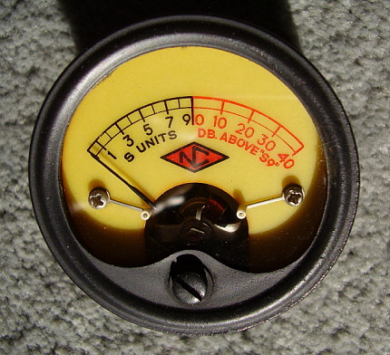
S-meter changed to an illuminated, yellow scale unit with 0-9 S-units in black and +10db to +40db arc scale in red and "DB OVER S-9" in red. Marion Electric meter. Installed by run-W. This corresponds with the change in the S-meter used in the NC-101X around the same time - early 1938.

ID tag added to upper right part of front panel - the uninformed would now know what kind of receiver they were looking at - mid-1938

Serial numbering system changed to numeral prefix with letter suffix - the "Z" prefix was used ~10/38  

1939 - Runs Suffix B to Suffix F

Antenna/ground terminal changed to polystyrene insulator and screw binding posts - the older "push" connector plastic top cap broke easily - new style connector by SN: 233-C

Model 697 power supply for 6.3vac tube HRO Sr. introduced ~3/39

2.5vac tube HRO not offered - only 6.3vac tubes used after ~4/39 - Millen recanted his opinion that the 6.3vac tubes caused modulated hum at 15MC in the receiver - improved tube quality sited

James Millen Resigns from National Company ~ 5/39  -  James Millen left National in May 1939, officially to form his own company, James Millen Mfg. Co., but here's what Millen himself had to say about his leaving, as told to John Nagel K4KJ and reported in his "Brief History of the National Company, Inc."

National had been successfully building its reputation as a top shortwave communication receiver company. The sales and designs coming out of National were at the cutting edge. Unfortunately, the majority share holder at National Company, one Warren Hopkins, wanted National to suddenly change directions. Hopkins wanted Millen to switch emphasis from shortwave communications equipment and go into the consumer "home radio market." Hopkins thought this change would expose more of the public to National products by supplying "Wards" or "Sears" with home radios. Millen was adamantly against National changing direction. He had worked for the past eleven years to put National as the leader in shortwave communication receivers and, to Millen's dismay, it seemed that Hopkins (and perhaps some others in the company) wanted to abandon this successful business position. Millen resigned but National never went into the home consumer radio market at that time. Demands from WWII in Europe resulted in huge orders for HRO receivers which rendered the argument for change moot. Years later, in retrospect, Millen believed that Hopkins' position stemmed from a desire to maximize his stock value because of his terminal health issues and had nothing to do with National's long-term success.

Another version was related to me by George Meier based on what some of Millen's close friends told him.

It seems that Millen had gone to Washington D.C. to discuss the use of the HRO receiver in the military. At the meeting, Millen supposedly represented himself as president of National. Millen's "high profile" at National (and in National's advertising) did seem to promote the belief that Millen was "in charge" so apparently the "Washington crowd" believed that they were dealing with National's CEO. Somehow word got back to William Ready (the actual president of National Company) who was livid. During the meeting at National (upon Millen's return) Millen was asked to resign, which he did. It seems like an over-reaction on Ready's part, especially since the National-Millen publicity promoted "Millen as CEO" through most of the thirties.

This Washington DC story has some problems however. Millen was de facto running National. If it had been a problem for William Ready, one would think he would have brought it to Millen's attention years earlier. Millen was "high profile" because he literally was the only one at National that communicated to the amateur public. Millen actually personally answered many of the letters that came into National from hams around the country. He had a monthly open letter to hams that ran in QST magazine. Millen personally traveled around the country visiting hams and gathering information on what hams wanted from National. According to John Nagel, Millen along with his personal assistant, Frances Bearse, really did "run" National in the thirties. If Millen had represented himself as National's president in Washington D.C., it doesn't seem like it would have been much of a problem since he was, in fact, running the company.

To leave the successful position that Millen had at National, with his very "high profile" personality, must have been the result of a serious internal conflict. However, one should remember that Millen was still a young man when he left National. Perhaps the conflict with Hopkins was enough to force Millen's resignation and allow him to become the CEO of his own company, James Millen Mfg.Co. and not have to deal with the "Hopkins" of the corporate-world.

1940-1941 - Runs Suffix G to L

Tuning condenser insulators redesigned, shield thickness increased, improved grounding contacts for rotor (Suffix G-on)  - better performance with cost reduction

HRO Production and Engineering Changes from 1942 to 1953

1942-1945 - General Information - Various Production Runs during WWII

Bandspread coil production is significantly reduced (eliminated?) as the military production requires "J" series coil sets for A, B ,C and D frequencies. Most of WWII coil sets are JA, JB, JC and JD coil sets along with E, F, G, H and J coil sets. Coil set C, LO inductance adjustment is changed to a moveable "loop" as coil sets A and B.

Many HRO receivers will have audio output transformers installed to remove B+ from the speaker terminals. Sometimes seen pre-WWII military units but becomes common during the war.

RBJ, RAW and RAS introduced in 1941 for USN. These are rack mount HRO Junior receivers with speaker, power supply and coil storage box included in rack. RAS has 175kc IF for uninterrupted coverage from 190kc up to 30mc using seven coil sets. RBJ coils are apparently for 456kc IF but have some differences because the individual coil are identified with numerals that are different than either the HRO or the RAS. Power cable from the RAS was a shielded cable even though it was cloth covered.

HRO-M designation used for HRO with plug-in crystal on top of the crystal filter assembly. HRO-MX designation used for an internally-mounted crystal inside the crystal filter assembly.

USCG designation of RC-105 used for HRO Senior version with GC coil sets. Coil sets have metal ID plate. Speaker was designated R-115 and was 8" PM in the MCS cabinet with metal ID plate on upper right front of the cabinet. R-106 designation used by US Army Signal Corps for some HRO-MX receivers. Reception Set R106 designation used by British for some HRO-M receivers depending on service requirements.

Plug-in coil sets - front panel changed from 3/16" thick aluminum to 1/8" thick steel

Many of the slotted head machine screws used in assembly of various parts are replaced with hex head screws with .25" hex heads.

The gear box is changed from a casting to a sheet metal assembly with square edges and corners. "NC" is stamped-embossed on the sheet metal cap. This incorporates a mounting change from four fillister head screws for mounting the molded cap to only two hex head screws to mount the new style cap. Additionally, the sheet metal housing requires that a bronze bearing be installed at the rear to act as a thrust bearing for the worm gear. Also, since the sheet metal housing isn't as thick as the old cast gearbox, the condenser supports are now integral to the assembly which limits the clearance for the thrust ball bearing assembly. This forced the assembly of the ball bearing thrust assembly on the worm gear shaft to now have the ball bearing at the front of the shaft rather than next to the worm gear flange as originally designed.

During WWII the wrinkle finish paint formula was changed and the "wrinkle" tends to be much finer than early model HROs.

During WWII there were many variations of the HRO, the coil sets, the power supplies, etc., built for the Signal Corps, the Navy and for Allied use - not all variations are covered in this article.

Later HRO-MX receivers will have ID rings for AVC and B+ toggle switches. Many HRO-MX receivers fitted with Marion Electric 0-1mA scaled, non-illuminated, white scale S-meter. Toggle switch replaces the "pull-switch" for the S-meter function.

HRO-5 introduced in 1945 with following changes:

Change over to mostly JAN parts, specifically most resistors are changed to JAN type

All coil sets now have an aluminum, silk-screened panel that is mounted on top of the coil set panel to provide coil identification and provide a frequency graph and a logging chart

All coil forms used in all coil sets are now made out of polystyrene plastic

Crystal filter changed to internal mounted crystal. This change may have been incorporated earlier in some receivers but it is consistently used in the HRO-5 and later receivers.

Serial Number location changed to near AF Output tube and meter zero adjustment. This location is sometimes used in earlier "Lend-Lease receivers" with two prefix serial numbers.

Hum-resistor eliminated from tube heater circuit and one side of the heaters then connected to chassis instead

All tubes changed to octal tubes, all metal octal tubes except 6V6GT AF Output tube

S-meter is almost always a Marion Electric 0-1mA meter with white scale and non-illuminated

Cabinet changed to have no ventilation holes in back and no louvers on the sides.

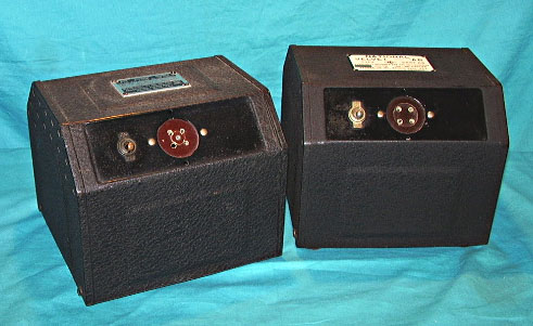
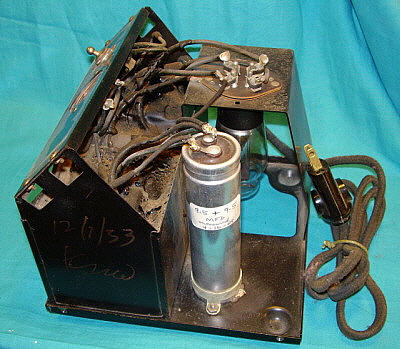
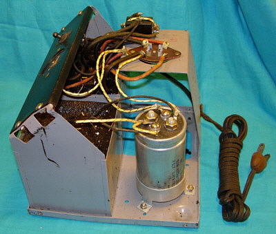
Heavy duty 697W power supply is introduced with square box type cabinet rather than the typical National "dog house" cabinet.

HRO-W produced for Signal Corps - mid-1945

Late-1945 - 1946 - General Information

Bandspread coil sets return to production. Possibly as early as September, 1945 - when civilian sales start up.

HRO-5 becomes HRO-5A when bandspread coils are supplied.

S-meter scale returns to a white scale with diamond "NC" logo installed in WWII Marion bakelite case. Some meters may be older Marion Electric types with round housing and yellow S-meter scale.

HRO-5A1 "early version" introduced around Feb or Mar 1946 - Features Noise Limiter built onto a small chassis. These receivers use many "left over" parts from WWII production and will be found with round Marion Electric S-meters from pre-WWII production, HRO-W front panels, National ID tag will be mounted above the NL control on receivers with WWII panels. When these panels run out, then the tag is returned to the upper right corner of the panel.

Meter Zero Pot location moved behind Audio Output tube socket

HRO-5A1 "last version" introduced July-Aug 1946 - Features an "improved" Noise Limiter circuit that is now built directly onto the chassis. NL circuit is slightly changed compared to earlier version. New "standard" circuit for Crystal Filter that uses a six-position Selectivity control and a variable capacitor Phasing control - end of the dual variable capacitor type Crystal Filter. Wider spacing between Selectivity and Phasing controls on new filter.

Also, for HRO-5A1 "last version" - New serial number location on rightside-top of chassis edge midway back

Also, for HRO-5A1 "last version" - New serial number format using three digits to identify the production run, a space and then four digits to identify the receiver

Also, for HRO-5A1 "last version" - Same cabinet as late WWII used with no ventilation holes in back or louvers on sides but "NC" decal now applied under lid (was discontinued during WWII)

Also, for HRO-5A1 "last version" - New S-meter with square shaped housing made by Marion Electric. Conformed with the S-meter used on the NC-240D

Also, for HRO-5A1 "last version" -  Cadmium-plated chassis replaces the gray-painted chassis

Also, for HRO-5A1 "last version" - Probable that almost all production of this version was on run 184. Run 184 uses serial numbers to over 1000 with 1054 highest reported. One reported HRO-5TA1 with SN: 189 0081 seems to indicate that the very first part of run 189, which was almost all HRO-7 receivers, did have some HRO-5TA1 receivers within it. The run 189 HRO-5TA1 receivers were probably using up as much of the surplus parts for the "black cabinet" HRO receivers as possible before the entire remainder of run 189 was just HRO-7 receivers.

Late 1946 - HRO-6 introduced with a supposedly "improved" Noise Limiter circuit, however this NL circuit is the same as that used in the "last version" HRO-5A1 - external and internal appearance of receiver remains unchanged from "last version" HRO-5A1. It's known that HRO-6s and last HRO-5TA1s were built with-in the same production run - run 184. See "HRO Serial Number Log" (above) -  the two reported SN for HRO-6 are production run 184 0297 and 184 0697 and eight of the HRO-5TA1 serial numbers are also production run 184. It's also interesting that four HRO-5TA1 receivers apparently have higher serial numbers than the highest HRO-6. It appears that the HRO-6 serial numbers are issued in a block between 184 02xx and 184 07xx but it's also possible that the serial number of HRO-6 and HRO-5A1 are intermixed on run-184. It's possible that National considered designating the "last version" HRO-5A1 as an HRO-6 since there were so many changes to that receiver from the proceeding versions. National probably stopped using the HRO-6 designation because of the developing design work for the HRO-7. From the serial numbers and known examples of the receiver it appears that only a small quantity of HRO-6s were so designated,...probably less than 100 receivers.

1947-1953 - General Information

HRO-7 introduced in Aug 1947 - major redesign of external appearance, coil graphs, coil removal levers (new,) voltage regulator added

HRO-50 introduced in 1950, followed by HRO-50-1 - major redesign of receiver with HRO-50 having built-in power supply, direct readout dial, push-pull audio - HRO-50-1 adds third IF amplifier and uses two dual-IF transformers

With HRO-50 or 60, coil mounting insulator blocks are changed to ceramic material. Switches are added to eliminate the need to move the four screws when changing to general coverage or bandspread

HRO-60 introduced in 1953, adds double conversion above 7mc. The 7mc coverage with double conversion requires that the user employ the B coil set in general coverage. If 40 meter bandspread coverage is desired then the C coil must be used and this coil operates in single conversion. Additional coil set offered  - 15M (BS only,) 10M (BS only) and 6M coil sets available


HRO Accessories

Most of the following items are actually necessities for operation of the receiver and some, like the four coil sets A, B, C & D, were included with the purchase. However, power supplies, speakers, coil boxes and extra frequency coverage coil sets were optional and added to the total cost of a receiver. I've also included National's Servicing and Upgrading as this was an option that many owners took advantage of.

HRO Coil Sets - Detailed Information


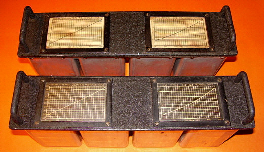
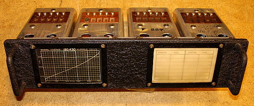
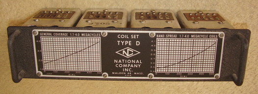
photo above: Top coil set is from HRO sn: F-13 and shows the white background graphs. Bottom coil set is from a later HRO Senior showing the black background graphs

General Information - Each of the HRO coil sets consist of four shielded coil assemblies that function in the receiver as the 1RF, 2RF, Mixer and Local Oscillator tuned circuits in conjunction with the HRO receiver's tuning condenser. The early coil sets were identified by the users by looking at the graphs and seeing what frequencies were covered, however, National identified each coil set with a letter. Coil sets A, B, C and D covered 30mc down to 1.7mc and could also be set to bandspread the 10M, 20M, 40M and 80M ham bands. Very early on, the E and F coil sets were added. These two coil sets allowed coverage of the AM BC band and provided the user with coil set E that would cover 160M and also allow leaving the D coil set covering 80M bandspread. Eventually, coil sets covering the long waves were provided with G, H and J coil sets allowing coverage from 430kc down to 50kc with a small section of the spectrum around the receiver's IF not covered (430kc - the upper frequency of the G coil to 480kc the lower frequency on the F coil.) During WWII, almost all A, B, C and D coil sets produced were of the "J" series, or HRO Junior coil sets that didn't provide the bandspread function. Many WWII coils sets had small aluminum tags installed between the frequency graph and the logging chart for coil set identification. Very late in WWII, a silk-screened panel was introduced that showed the tuning range graph with logging chart and the coil set identification by letter. These remained on the post-WWII HRO-5A and HRO-5A1 receivers with a bandspread graph added in place of the logging chart on sets A, B, C and D. The HRO-7 changed the metal tag to a rather long frequency graph for general coverage and bandspread with coil set identification. The HRO-50 and 60 use only a letter identification on the coil set panel. The HRO-50 letter ID is engraved while the HRO-60 uses a medium-sized rectangular metal silk-screened tag. Early coil panels are made out of 3/16" aluminum. During WWII, the panel material was changed to 1/16" thick steel.

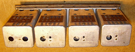
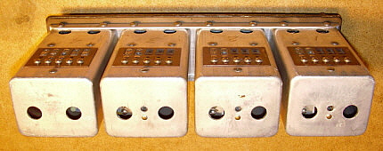
Early Production - The coils sets that were provided with the HRO receivers in the first two production runs are somewhat different from later production. The photo above shows the early white background frequency charts used on early coil sets compared to the black background charts used on most of pre-WWII production. To the right shows the alignment access holes used in early coils (photo A) versus the access holes in later coil sets (photo B.)

A

B

In the photos to the right, Photo A shows the contact insulators used on early coil sets from the first two production runs. Note the small contact buttons and the lack of any nomenclature except for the "B3" engraved coil identification. Photo B shows the type of contact insulator used on coil sets up to the change to ceramic insulators for the HRO-50 series. Note the larger, two piece contact buttons and the embossed nomenclature "NATIONAL CO." along with the "NC" diamond logo and contact button number identification, which is difficult to see but consists of a number below the contact.

A

B

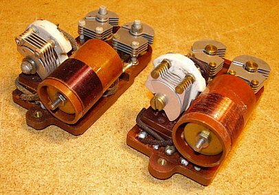
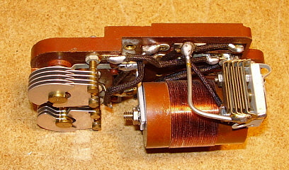
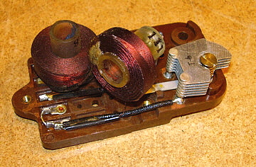
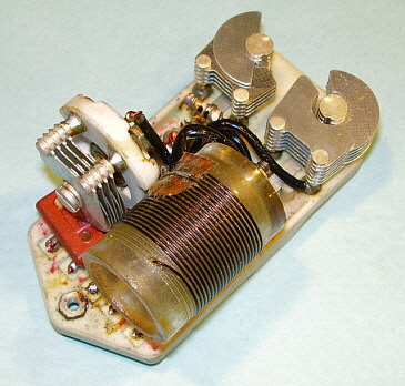
Coil Assembly Construction and Alignment - The two holes on the top of the coil shield allow access to the trimmer capacitors for general coverage or bandspread alignment. Coil sets E, F, G, H and J provide a padder adjustment on the LO coil that is accessible from the top of the coil set since the bandspread function is not provided on these coil sets. The holes in the rear of the coil shield allow access to the padding capacitor that is used for bandspread only or the LO inductance adjustment for general coverage. The LO inductance adjustments on coil sets C and D consist of the brass metal disk inside the coil form that rides on a threaded rod. The metal disk is spring-loaded to retain its adjustment and can be changed by rotating the disk on the threaded rod using the hex nut provided to move the disk further into or out of the coil form. Since the disk is made out of brass, the further into the coil the disk is moved the lower the inductance is adjusted. Note in the photo to the right the various adjustments provided on the Local Oscillator coil. It can be seen in the photo that both coil assemblies use the brass disk for general coverage inductance adjustment. Differences are that the coil assembly to the left is from a very early coil set (D-run) and has a hex head adjustment on the bandspread padder condenser. The newer coil assembly on the right is from a 1936 coil set (J-run) and it can be seen that by this time the bandspread padder is slotted for screwdriver adjustment. The upper air variable capacitors are general coverage and bandspread trimmer capacitors. It can be seen that the type of air variable was changed to a more "fixed" assembly by replacing the hex nut and threaded end on the rotor with a press-fit rotor plates into the brass rotor shaft assembly. This applies to the bandspread padder also.

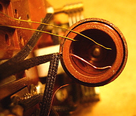
Since coil sets B and A are operating at a much higher frequency, a different LO inductance adjustment is utilized. This inductance adjustment consists of a loop of wire at the end of the coil wrap that is located inside the coil form. By moving this loop's position, the inductance of the coil is changed. The loop from an A coil can be seen in photo A to the right. During WWII, coil set C LO was changed to "loop" adjusted L.

In photo B to the right, note the compensation condenser behind the bandspread padder condenser. Note also that this padder adjustment is a compression capacitor. This is a Mixer coil assembly showing the difference in construction.

Nowadays when aligning the HRO coil sets, just adjusting the top trimmers will usually align the coil sets fairly well. See "Restoring and Aligning HRO Coil Sets" in the section below for more details on alignment. Also, all HRO manuals have the detailed procedure for full receiver alignment and owners should use that as a reference as well.

A

B

Individual Coil Assembly Identification - Looking closer at each individual HRO coil assembly, it will be noted that a number and a letter are engraved into the insulator block of each of the coil assemblies that make up the coil set. The letter will designate the frequency range and the number identifies the function of the particular coil. Thus coil assembly "C3" is the Mixer coil for the 3.5-7mc tuning range or coil assembly "A4" is the LO coil for 14-30mc. During WWII, the RAS version of the HRO Junior was built for the USN. To have this receiver tune uninterrupted from 180kc up to 30mc, it was necessary to move the IF down to 175kc. This will require slightly different coil assemblies and these were given a different identification code. A coil set for the RAS that has a coil assembly marked "G6" will indicate that the assembly is RAS RF2 for 180kc to 430kc. The only RBJ coil I've seen is a 50kc to 100kc LO coil that was identified as "J12." Also, on other J coils (50 to 100kc) the HRO-W RF1, RF2 and Mixer coils are marked J1A, J2A and J3A while the LO coil is marked as J4. The various codes are shown below. During WWII, the engraved coil ID was changed to an ink-stamped ID and remained ink-stamped through the HRO-60 production. Since it's very easy to remove the coil assemblies for cleaning and restoration, it convenient that each one can be easily identified for proper reassembly. 
 

Frequency Ranges 

A =  14mc to 30mc (BS 10M)

B =  7mc to 14mc (BS 20M)

C =  3.5mc to 7mc (BS 40M)

D =  1.7mc to 4mc (BS 80M)
E =   .9mc to 2.0mc

F =   .48 to .92mc(or.5mc to 1.0mc )

G =  180kc to 430kc

H =  100kc to 200kc

J =   50kc to 100kc
 

AA = 27.5mc to 30mc

AB = 25mc to 35mc 

AC = 21mc to 21.5mc

AD = 50mc to 54mc

ADX = 35mc to 50mc
 

Coil Function

Standard HRO with 456kc IF

1 = RF1      2 = RF2     3 = Mixer    4 = Oscillator

RAS version with 175kc IF

5 = RF1      6 = RF2     7 = Mixer     8 = Oscillator

                        RBJ version with 456kc IF (reason unknown)

                           9 = RF1     10 = RF2    11= Mixer   12 = Ocillator

Band Spread - On pre-WWII coil sets, the tuning range graphs can instantly identify a coil set as belonging to the bandspread types A, B, C and D by the fact that two different graphs are provided. The left side graph is for general coverage and the right graph is for bandspread. Switching this function is accomplished by moving a 4-40FH screw from threaded holes in each of the insulator blocks - see photos above. The screw position should correspond with the position of the proper graph to select either general coverage or bandspread, e.g., screw in left hole = general coverage, screw in right hole = bandspread. NOTE: Only the A, B, C and D coils sets can be set to bandspread the amateur bands 10M, 20M, 40M and 80M.

The bandspread option was eliminated from most of the WWII coil sets. When the bandspread option was eliminated from the A, B, C or D coils, a "J" was added as a prefix, thus a non-bandspread "C" coil would become a "JC" coil. The "J" prefix originally came from the pre-WWII HRO Junior coils that were non-bandspread coils but was later applied to many coil sets used during WWII. Some coil sets will have numerical identification with the various USN versions of the HRO Junior known as the RAS, RBJ or RAW having coil sets numbered 1 through 7. The HRO- 5 and the HRO-W (Signal Corps) were also provided with "J" prefix coil sets. Post-WWII coils return the bandspread function to the A, B, C and D coil sets.

Coils with "J" Prefix

"J" prefix on Frequency Range on A, B, C & D coil sets = Non-band spread version (HRO Jr. and most WWII coil sets)


Coil Set Serial Number Location - Since the coil set of four A, B, C & D were sold with the receiver, they are serialized with the same letter-number combination as the receiver. The original four coil sets were aligned to their specific receiver, thus the importance of having the "matched" original coil sets. If optional coil sets were ordered post-purchase of the receiver then coil sets were not serialized. If optional coil sets were ordered with the receiver then generally they were serialized since National aligned them before the complete order was shipped. Any of the coil sets, regardless of the serial number, can be used with any HRO but they must be aligned to the receiver that they are intended to be used with for best performance.

The coil serial numbers are usually stamped on the LO coil shield. Sometimes the serial number will be stamped on the Mixer coil shield or the upper rail of the coil support on the right side of the coil set. Any sort of cleaning, past or present, tends to remove the ink-stamped serial number so it's common to find coil sets that appear to be un-serialized. Depending on the cleaning, sometimes a "shadow" of the serial number can be discerned in certain light. By observing the various acceptance stamps and marks on the coil sets, it's possible to see a similar markings within a receiver's four coil sets that would tend to confirm that a complete set is matched to the receiver, even if the serial numbers have been removed by cleaning. Some of the acceptance markings were in wax crayon and other more resistant material and these usually survive moderate cleaning efforts.

Medium Wave & Low Frequency Coil Sets - Coil sets E, F, G, H and J cover the frequency range from 2000kc down to 50kc with a 50kc gap around the 456kc IF of the HRO. All of these coil sets had only one graph provided since band spread was not available. E and F provided a logging chart for favorite AM BC stations. MF and LF coil sets G, H, and J also provided logging charts for coastal station settings and other types of stations that were operating in that region of the spectrum. The plastic cover that was installed over the logging chart was a matte finish that allowed writing (in pencil) on its surface, thus stations could be logged without removing the frame and plastic cover to write on the paper logging chart. The "pencil on plastic" writing could be erased if station logging changed. Buying the E coil provided a ham with a way to have 160M coverage and then to have the D coil set to bandspread the 80M band. E and F coil sets were fairly popular sellers with the hams and it's not too unusual to find an HRO that has six original coil sets A through F.

photo right: G coil set showing the logging chart with matte finish plastic cover that could be written on with pencil

The G, H and J coil sets were more for commercial use at shore stations, airports and with other users that needed coverage of the lower medium frequency range and low frequency range. During WWII, most HRO receivers were equipped with full sets of coils, so it's not uncommon to find the military versions of the G, H and J coil sets. During the 1930s, 40s and 50s, most (if not all) ship to shore traffic, ship navigation, air navigation, weather forecasts for aviation and sea, time signals and the military (especially the Navy) were on the lower frequencies and the amount of interesting signals found there was incredible. Even LW Broadcasting was available in Europe and Asia (and some of the stations could be received in other areas of the world.) Listening on the lower frequencies was extremely popular. Of course, the use of the "long waves" has changed over the decades since then and nowadays almost all of the signals in that region of the spectrum are now using digital or data transmissions. If you listen below 530kc without the receiver's BFO turned on, you'll hear very little. This has led many casual listeners to believe that nothing can be found below the AM BC band. Additionally, this part of the radio spectrum is subjected to a lot of man-made noise along with considerable noise from solar activity. Special antennas are sometimes required for successful reception of signals below 530kc.

photo right: This is the "H2" coil (RF2) from an H coil that covers 100kc to 200kc showing the much larger inductances required to tune in the LF range. Since the H coil is a general coverage coil only one trimmer capacitor is required. This is a WWII vintage coil assembly showing the polystyrene coil forms.

Post-WWII Coil Sets - During WWII, probably with the HRO-5/W, all of the coil forms used in all of the coil sets were changed from the brown phenolic material to polystyrene. Polystyrene plastic was used up through the HRO-60 production. With the introduction of the HRO-7, levers were installed on the receiver to allow extracting the coil set and the coil set panels had guide pins that interfaced with the levers. This eliminated the grab handles on the coil set panels. This type of coil panel with guide pins was in use through the HRO-60 production. These later coils had ceramic insulator blocks that integrated switches that easily allowed selecting bandspread or general coverage. These switches eliminated the nuisance of moving the 4-40FH screws to go from general coverage to bandspread.    >>>

photo right: Post-WWII coil sets showing the HRO-5A1 coil set style with silk-screened panel that incorporates the graphs and coil set ID. The HRO-5A1 coil sets were the last type to use the grab handles.

>>>  With the HRO-60, double conversion was added to the receiver. The actuation of the switch to accomplish the conversion is provided by the particular coil set installed in the receiver. Since double conversion only affected coil sets A and B, along with the other "A" prefix coils sets, AA, AB, AC, AD and ADX, only these coils sets had a hole located in the LO coil shield between the two rear alignment access holes. This additional hole is a clearance hole for the double conversion switch. When coils sets are installed that don't have the clearance hole, the switch is kept from actuating, keeping the receiver in single conversion. When any A prefix, A or B coils were installed into the receiver, the double conversion switch was actuated by allowing a switch lever to protrude into the clearance hole.
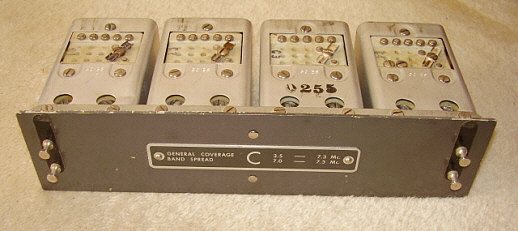
photo left: Close-up of the LO coil assembly from an HRO-60 C coil set. Note that the insulator base in now made out of ceramic. Note also that the coil form is polystyrene which had been in use since late WWII.

photo right: HRO-60 C coil set showing the metal ID tag, the locating pins, ceramic insulator blocks and the switches that allow selecting either general coverage or bandspread. The earlier HRO-50 coil sets will have the identification information engraved into the front panel of the coil set rather than the aluminum ID plate. Note that only the last four digits of the entire receiver serial number is stamped on the coil sets. In this case, located on the mixer coil shield is "0255" which is from HRO-60R sn 393 0255.

Restoring and Aligning HRO Coil Sets

Nearly all of the HRO receivers that are found today are missing most (if not all) of their original coil sets. This means that most HRO enthusiasts are always on the lookout for "orphan" coil sets, that is, coil sets that, for some reason, have become separated from their original receiver. These coils sets generally require a little work to have them "match" the intended HRO receiver. Additionally, every coil set that is going to actually be used in a receiver should be disassembled and thoroughly inspected, cleaned and then reassembled. After this procedure, the coil set will have to be aligned to the HRO receiver that it is going to be used with. This procedure assures that peak performance will result with the new coil set operating in its new "parent" HRO receiver.

Disassembly and Cleaning - All four of the coil assemblies are mounted inside aluminum coil shields that are mounted to the coil set front panel by four screws that "clamp" the coil shield to the rear panel. By loosening these screws (just loosen them) the entire coil assembly is pulled off of the rear coil panel. Now, remove the three screws on top of the coil shield that mount the coil insulator and slide the coil assembly out of the coil shield. You'll usually find spider webs, dead insects, dust and dirt, all depending on how and where the coil set was stored. Inside the aluminum coil shield will also have a lot of residue that should be removed. Clean by "dusting" - that is - use a soft bristle paint brush to dust off the dirt and insect debris. Be careful of the fine wires that connect the coils to the contacts. Carefully inspect all of the solder joints for cracks or poor soldering. Check the condition of the coil and dust off any residue. Check the trimmer capacitors for bent plates. If everything looks good, spray a very small amount of De-Oxit on the rotor contact and the adjuster screw plate and rotate the trimmer capacitor several turns to clean the contacts. Always use a 1/4" Nut Driver to do this operation as this will prevent damage to the slots on the trimmer adjustments. Be sure to return the trimmers approximately to their original position. Return the coil insulator assembly back into the coil shield and install the three mounting screws. Install the entire coil assembly back onto the coil panel. Repeat this procedure for each of the four coil assemblies. When reassembly is complete, the coil set is now ready for alignment in the intended "parent" HRO receiver.

Slotted Adjustment Screw Heads - These "domed shaped" adjustments for the trimmers on the coil sets were actually made at National. The original adjustment heads were hex shaped brass. National added the dome using solder and then slotted it so the trimmers could be adjusted by either a hex tool or with a blade screwdriver. Sometimes you'll find the domed heads so "gnarled" that the screwdriver blade won't move the trimmer and just slips out of the slot. You can resolder a new domed head on the bad trimmer and then slot it with a hack saw blade. Remove any residue afterwards. Also, shape the slot carefully so maximum blade contact is assured. This way the new slot will work fine. Be sure to re-lube the associated trimmer since the heat may have vaporized the old lube.

Cosmetic Restoration

Many times, the "orphan" coil sets we find are not specifically the type for the intended "parent" receiver. Maybe the coil set might be a military version with a steel panel but we want a pre-war coil set with an aluminum panel. Luckily, the coil assemblies themselves are interchangeable and can be interchanged from steel panels to aluminum panels with ease. All of the WWII production of A, B, C and D coil sets are non-bandspreading J-type coils. So, while electronically these coils certainly can be used, they wouldn't be proper in a pre-war HRO Senior. If everything is correct and only a coil assembly swap and chart-graph transfer is required the entire procedure can be accomplished in a few minutes.

Sometimes, the coil panels we have to use are painted incorrectly for the intended receiver. Sometimes, the charts-graphs coverings are in bad condition or missing. More than once, I've found coil panels where the grab handles were sawn off so the coil set could be used in an HRO-7 or later receiver. All of these conditions will require repainting the coil panel.

Strip the coil panel of coil assemblies and the charts-graphs. Use stripper to remove the old paint. Mask the rear of the coil panel. I use VHT Black Wrinkle Finish (BWF) paint which has a good pattern that is similar to the original. Apply a very heavy coat of BWF and apply heat, either using lamps or a hand-held heat gun. Let the finished paint set for several hours before moving the panel. Let the panel cure overnight before remounting the coil assemblies and charts.  

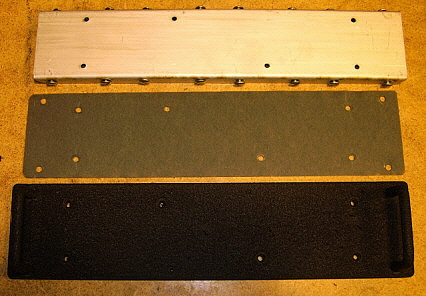
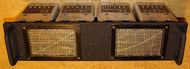
Where the handles have been sawn off you'll have to find a set of WWII HRO screw-on handles. The original handles used on the aluminum panels were swedge-mounted, which is why they were sawn off. You'll have to remove the rear panel by drilling out the rivets. What you end up with looks like the photo below-left, upper photo. Note there is a heavy paper gasket between the two panels. Mount the new handles using countersunk flat head screws. Then repaint the panel. Now, remount the rear panel using "fake rivets" made out of 6-32 FH screws. The screw heads will have to be turned down to fit into the small countersunk holes in the panel. Be sure that the screw doesn't protrude beyond the nut on the backside. If it does, it will interfere with the coil assembly insulator when mounting the coil assemblies. Mount the coil assemblies and then mount the charts and frames.  >>>

photo top: The three pieces that make up the coil panel. The handles are already mounted and the panel painted with VHT Black Wrinkle Finish paint. Note the center piece is the heavy paper gasket.

photo bottom: Completed A coil set that utilized the panel that had the handles sawn off.

>>>  If you need to repaint the metal chart-graph frames they should be semi-gloss black. I've found that many times the frames can be cleaned and polished using Wenol's chrome polish. This is the British version of Semi-chrome. The Wenol's polish will result in the frames looking in reasonably good original condition. When trying to match the coil set with an original finish HRO you don't want the coil set to look perfect - it wouldn't match.

Chart-Graph Plastic Covers - Nearly always these plastic covers have wrinkled and yellowed. I use them as original unless they are so bad that you can't read the graphs. If I have to replace a poor condition plastic cover I use the plastic material from the really cheap picture frames you find at the "Dollar Store." The plastic in these picture frames is just the right thickness and pliability of the original covers. Use the metal chart-graph frame as a template to cut the plastic to the same exterior size as the frame. Use a hot soldering iron with a "pencil tip" to make the mounting holes in the plastic. Just hold the plastic to the frame and push the hot soldering iron through the frame hole and you'll end up with proper size and location mounting holes. For the plastic cover on the logging charts, I use a slightly thicker and harder plastic found on other "not-so-cheap" picture frames. It's still very thin plastic but a little more rigid. This plastic can be sanded with 400 grit alu-oxide paper (go in just one direction when sanding) to make the surface look matte or semi-transparent. The mounting holes are done the same way with a soldering iron. When mounted, the logging chart is easy to read and the plastic cover can be written on with a pencil. If the "cheap-o" picture frames can't be located, check stationary stores like Office Depot for plastic dividers or plastic envelope document protectors. Also, some vacuum molded containers for pastry items can be used. There are lots of sources for thin flexible plastic material.

Chart-Graph Copies - If copies of original charts or graphs must be made to replace missing or damaged charts there are two methods. If you have original graphs to copy for the coil set you're restoring then be sure to copy them on to Manila-color or light tan color paper. Copy in black only - not color. This way the charts will look "aged" and original. Some HRO charts are available as scans on the Internet and if these are your source for the graphs then still print out on Manila or light tan color paper for best results. Also, don't buy an entire ream of colored paper. Stores like Office Depot will sell you individual sheets of colored paper (two cents a sheet last time I bought some.) The individual pieces of colored paper are available at the "self-serve copy" section of the store.

Coil Sets - Basic Alignment

Once the coil set has been thoroughly inspected, cleaned (if necessary) and has had the adjustments lubed, it can then be aligned to a specific receiver. Each of the top holes are assigned numbers 1 through 8 with 1 being the hole on the left. All General Coverage adjustments are made with even number holes and all Band Spread adjustments are made with odd number holes. The adjustments are as follows:

2 = 1RF      4 = 2RF     6 = Mixer     8 = LO    -   General Coverage Adjustments

1 = 1RF      3 = 2RF     5 = Mixer     7 = LO    -    Band Spread Adjustments

On the back of the shield/can of the LO coil there are two holes. The hole directly behind 8 is the inductance adjustment for General Coverage. The hole that is directly behind 7 is the padder for the low end of the Band Spread coverage. There are padders for the Mixer and the two RF stages for Band Spread adjustment and coil loops for General Coverage inductance adjustment but these very seldom require adjustment. If, after completing the full alignment of the coil set, it doesn't have consistent gain across the entire tuning range, in either General Coverage or Band spread (exclusive of antenna resonance changes) then possibly these adjustments have been tampered with. They are adjusted at the low end of the tuning range for maximum response. Again, these seldom need any adjustment. To check the low end alignment on the Mixer and two RF stages you can use a pencil's eraser end and push the outer plate of the tuning condenser section for the stage being tested. If the gain drops by moving the condenser plate in either direction - that is, either away or towards the adjacent plate, then that stage is "in tune." If you get an increase in gain as you move the outer plate as described then that stage needs to be adjusted on the low end inductance (or padder.)

For J Series Coils and the other non-band spreading coils (E, F, G, H and J) these are the adjustments:

2 = 1RF     4 = 2RF     6 = Mixer    7 = LO padder    8 = LO trimmer

8 is adjusted at the high end of the range while 7 is adjusted for the low end of the range. 2, 4 and 6 are adjusted at the high end of the range.

Coils sets must be adjusted in the General Coverage range first. So, install the 4-40FH screws in each of the coil insulator blocks into the left side screw hole (this selects General Coverage.) Install the coil into the receiver. Let the receiver warm up at least 15 minutes along with the test gear. You can do so quick trim adjustments but the final settings should have the coil in operation in the receiver for about 15 minutes minimum. 

Tune the receiver to the high end of the range and check the graph for the proper PW-D setting versus the frequency tuned. Most of the coil sets tune to 490 on the PW-D at the highest marked frequency on the graph. Not all coils sets are the same so check each graph to be sure of the correct frequency. Input that frequency into the Antenna input of the receiver. Be sure the signal generator is accurately set by using a digital frequency counter to check the actual frequency input. Keep the amplitude of the signal generator as low as possible and yet still have a signal that can be heard in the receiver and measures about mid-scale on the S-meter. You'll have to use a 400Hz modulated signal from the generator and then have the receiver in AVC with the BFO off for the S-meter to function. Now, adjust 8, 6, 4 and 2 for peak. Then tune the receiver to the low end of the graph frequency. This will be around 20 or so on the PW-D. Again, not all of the ranges are the same so check the graph to be sure. Adjust the inductance adjustment that is directly behind 8 for the low end. This will require removing the coil set from the receiver, making a slight change in the adjustment and then returning the coil set to test. You will have to turn off the B+ each time you remove the coil set and turn on the B+ after the coil set is reinstalled in the receiver. Remember that this inductance adjustment will affect the trimmer adjustment (8) so you will have to go back and forth a few times to get the coil to track correctly. Once the tracking is correct, then re-peak 6 and 4 at the high end of the dial. Now with the receiver connected to a tuned antenna for the high end ham band of this specific coil set, adjust 2 for the highest reading on the S-meter. Return the signal generator to the receiver Antenna Input for the next set of adjustments.  >>>

>>>  Once the General Coverage is tracking correct remove the coil set and move the 4-40FH screws to the right side hole for Band Spread coverage. Return the coil set to the receiver and tune to 450 on the PW-D. On coils sets D, C, B and A the ham band spread coverage is 450 to 50 on the PW-D. Check the graph for the proper high frequency input. Remember, some of the ham bands are different today then they were pre-WWII. For example, 20 meters' high end was 14.4mc then instead of the 14.350mc that it is today. Set the receiver to correspond to the graph. Adjust 7, 5, 3 and 1 to peak. Now tune the PW-D to 50 and input the correct low frequency and adjust the padder that is directly behind 7 for peak. Again, you'll have to remove the coil set each time to make the adjustment and then return the coil set to the receiver to check. Again, the adjustments do interact so both trimmer 7 and the padder adjustment will require a back and forth procedure until correct tracking is achieved. Once correct tracking is set now adjust the PW-D to 450 and peak trimmer 6 and 4. Now connect the receiver to a antenna that is tuned for the amateur band that is the Band Spread coverage and adjust trimmer 1 for a peak reading on the S-meter.

This completes the alignment of this coil set. Remember, since there isn't an Antenna Trim control on the HRO you must set the 1RF for peak S-meter reading on the ambient noise using the intended antenna for that band. You have to do this in both General Coverage and in Band Spread.

Images While Aligning Coil Set A - The A coil set is the most prone to misalignment due to peaking the adjustment response on an image. About half of the A coils I've tested were found aligned to an image. To avoid this always use the lowest possible signal level input from the signal generator. The image response is usually at a lower amplitude level than the proper signal response. On the A coil set only, the image will be below the proper signal by 912kc. This is one way to check to make sure that the LO section is set correctly. Also, when checking the tracking, if you're aligned to a image, the tuning will not correspond to graphs. When checking General Coverage, check 20mc WWV and 15mc WWV to be sure they are tuned at the proper PW-D reading (~ 230 for 20mc WWV and ~ 60 for 15mc WWV.) When checking the Band Spread (which can also be adjusted to an image independently from the General Coverage) test the tuning at 29mc and 28mc to see that those check points are correct.

When the tracking is correct on both GC and BS test the output response of the receiver across the tuning range in both GC and BS. If in GC it is consistent and maintains good sensitivity across the entire range then the Mixer and RF stages are aligned properly. If you find that the sensitivity falls off in the center of the tuning range or dramatically changes from one end to the other then it's likely that the Mixer is aligned to an image. Try aligning the Mixer to the other peak and recheck the coil tracking. If the improvement is noticeable then you were aligned to an image.

Without a doubt, the A coil set is the most difficult to get aligned correctly. It will take time and a lot of rechecking of the settings. When it is aligned correctly, the HRO performance is incredible on 14mc to 30mc. Since so many A coils are aligned to the image rather than the proper settings the performance of the HRO on the higher frequencies is sometimes thought to be rather poor. This isn't the case. With a properly tuned antenna (not an un-tuned random length wire) 10M performance will be surprisingly good. Also, the stability of the frequency is very good when the A coil set is cleaned and aligned properly.

Poor performing A coils should be checked thoroughly, cleaned carefully and then lubricate the trimmer contacts. Be sure to clean the contact buttons with De-Oxit. Follow this with a careful alignment and your HRO should perform very well up to 30mc. Be sure to consider though, you are using a mid-1930s designed receiver, so don't expect 21st century performance. However, you should be very pleased at the high frequency ability of the HRO.


The Various National Co., Inc. Power Supplies

Initially, there was only one of the smaller power packs ( the "Dog House" style) that could be used with the early 2.5vac HRO - the 5897. The 5897 was originally designed for the SW-5 receivers in 1930 but was later redesigned for the FB-7 receiver in 1933 and designated 5897AB. It had enough current carrying ability to operate the HRO. In fact, many early HRO receivers were paired with 5897AB supplies that have printed on the top ID label "Especially Designed for the FB-7." Under full load, the 5897AB will provide 2.5vac heater voltage at the receiver and +230vdc B+. All of the National power supplies have an increased tube heater voltage at the transformer to compensate for the IR drop across the power cable to the HRO (or other receiver.) There were also rack mounted power supplies, the GRSPU to operate a single receiver and the GRDPU for operating two receivers. Either rack supply could be ordered for either 2.5vac, 6.3vac (or a combination of the two) heater voltages. All of the power supplies used an 80 type rectifier and were a pi-type filtering system consisting of two filter capacitors (generally 8ufd) and a filter choke. A bleeder resistor wasn't used.

Be aware that there are a few of other "dog house" power supplies that look just like the HRO types but do not have the current carrying ability to operate the receiver properly. For instance, the 5887 was another FB-7 power supply but its B+ rating is for +180vdc. The 5886 was designed to operate the National SRR and later the 1-10 receiver. Although it will seem to operate a 6.3vac HRO Senior, actual measurement of the B+ will show that the B+ is around +170vdc. National did publish that the HRO would operate on B+ as low as +135vdc but added "at some sacrifice in performance" (which was mostly audio output related.) There is also the 5880 power supply that was advertised for the SW-3 or FB-7 receivers, though similar in appearance, it also has low B+ voltage of around +175vdc. Many HRO enthusiasts do use the 5880, 5886 or 5887 to operate their HRO receivers because they feel that the stability and sensitivity is improved at the lower B+ voltages. Even James Millen recommended +180vdc B+ at one time in one of his QST letters. I've tried operating the HRO receivers from +175vdc up to +240vdc and haven't noted any significant changes in performance within that range of voltages. Only the audio output is slightly less at the lower B+ voltages. Stability and sensitivity changes would require actual measurements to for comparison but I would expect that lower B+ voltages would benefit these two areas of performance.

photo above:  Power Supply Model 697 on the left and the earlier "Velvet AB" 5897AB Power Supply on the right.

The later (1939) Model 697 "Dog House" was designed to operate the 6.3vac HRO Senior receivers and provides the correct voltages under load. During WWII, a heavy-duty 697 was produced, the 697W. It is has a square housing, plug-in electrolytic can capacitor and is usually fungus proofed. The later 697 power supplies will have a switch to select the primary voltage, 115vac or 230vac. There were also two DC versions, the 686 for 6vdc operation and the 1286 for 12vdc operation. Both were vibrator-type power supplies with the 686 powering a standard six-volt HRO while the 1286 powered a special HRO, the HRO-12S that used 12 volt tubes. The 686 used a 6X5 rectifier and the 1286 used an 0Z4 rectifier. Post-WWII HRO-5C receivers used a chassis-built 697 power supply with 5Y3 rectifier and potted power transformer. It mounted on top of the coil box in the rack.

The internal construction of the "Dog House" power supplies are all similar in that two sheet metal boxes contain the power transformer in one box and the filter choke in the other box. Both boxes are filled with a black tar-like wax to keep moisture out and to prevent noisy operation. Typically, a dual or triple filter capacitor is mounted to the inside base using a clamp-type holder. Triple capacitors had two sections connected in parallel for the output capacitance of the pi-filter.


photo above: The 5897AB "FB-7" power supply showing the construction of the chassis and how the choke and power transformer are encased in tar. Note the date written in orange crayon, Dec 1, 1933.


photo above: This shows the 697 power supply from 1946. Note that the construction of the chassis hasn't changed much, only it is now painted gray. The filter capacitor is now a three capacitor unit (8+8+8) but the output cap is actually tied in parallel (see jump on cap terminals.)

The power switch and the four-pin output socket are mounted to the angled panel. The power cord is routed through a grommet that is mounted to the chassis. The black wrinkle finished housing slips over the chassis and is mounted with four sheet metal screws.

Generally, to be able to safely use any of the "Dog House" power supplies it will be necessary to replace the filter capacitors. The original dual or triple capacitor can be left in place and modern tubular electrolytic capacitors connected to the wire lugs after they have been disconnected from the original capacitor's terminals. For a more original appearance, it's also possible to rebuild the old filter capacitor by installing new electrolytic capacitors inside.

I've tried re-forming the originals and have had fairly good luck doing so but make sure that the current drawn by the individual capacitors doesn't exceed 100uA at full voltage after reforming. Most original capacitors will end up with about 10 to 100 times that current draw at full voltage and while they may work okay for awhile, they should be replaced as a safety measure.

National Co., Inc. Power Supply Data

  PS TYPE                     INPUT/OUTPUT VOLTAGES                          RECEIVER

5897, 5897AB         115vac in, 2.5vac 10A, 230vdc 70mA                   SW-5, FB-7, HRO
GRSPU                     115vac in, 2.5vac or 6vac, 230vdc 70mA                    HRO, HRO SR.
GRDPU                     115vac in, 2.5vac or 6vac, 230vdc 70mA               (2) HRO, HRO SR.
697 (early)               115vac in, 6.3vac 3.5A, 230vdc 70mA                          HRO SR.
697 (late)                115/230vac in, 6.3vac 3.5A, 230vdc 70mA              HRO-5, HRO-5A, A1
697 (late-chassis)    115/230vac in, 6.3vac 3.5A, 230vdc 70mA             SPC unit for HRO-5C
697W (MIL)            115/230vac in, 6.3vac 3.5A, 230vdc 70mA                 HRO-5, HRO-W
686                           Battery, 6vdc in, vibrator type, 230vdc 70mA             HRO SR., HRO-5
1286                        Battery, 12vdc in, vibrator type, 230vdc 70mA             HRO-12S only
5886                        115vac in, 6vac 3.5A, 180vdc ~ 70mA                       SRR, 1-10, AGS
5887                        115vac in, 2.5vac 10A, 180vdc 70mA                         alternate FB-7 ps
5880                        115vac in, 2.5vac ~5A, 180vdc ~ 40mA                              SW-3

If the choke is open or if there is a power transformer problem then the black wax will have to be melted out. This is messy and difficult to accomplish requiring some way to heat up the entire chassis. Heat guns and propane torches don't apply enough heat evenly to remove all of the wax. Larger toaster ovens may work. I usually buy them at the "thrift stores" for a few bucks and then throw them away after they have served their purpose. Low heat, 200º to 250º F, is sufficient to melt out the wax since the heat is even and continuous but it will take an hour or so for all the of wax to run out. Replacement chokes aren't too much of a problem but a defective power transformer might be difficult to replace since the heater voltage is somewhat higher than standard to compensate for the IR drop across the power cable of the HRO receiver. Sometimes vintage power transformers from late-twenties or early-thirties console radios could work. These transformers were originally designed for 110vac input and at today's higher line voltages (115-120vac) the 2.5vac filament would be about right and the older B+ of around +180vdc used on this vintage tubes is about right for the HRO (probably around +200vdc with today's line voltages. A custom-built transformer would be an expensive solution since it would probably cost more than just buying another "Dog House" power supply. Fortunately, the choke and the power transformer seem to be pretty robust and are seldom a problem.

Pin Outs - The schematics were always vague about the four pin socket connections. Some schematics had a drawing of the plug but many early schematics didn't even show the plug. Anyway, all of the power cable plugs and the power supply sockets are wired the same.

Pin 1 = FIL AC (10 gauge wire with red insulation in Cable)    

Pin 2 = B+ (18 gauge wire with blue insulation in Cable)    

Pin 3 = B-/Chassis (18 gauge wire with green [early] or yellow [late] insulation in Cable)    

Pin 4 = FIL AC (10 gauge wire with black insulation in Cable) .

The power supply internal wires are always black in early versions and various colors in later supplies. The pin outs are always the same.

Home Brew Power Supplies - Since the HRO was usually offered with the power supply as an optional purchase, there are some home brew power supplies around that range from crude efforts to nicely designed and built units. It isn't difficult to build a better power supply than the one that National offered. After all, it was being built during the Depression, so the use of pi-filtering provided adequate hum reduction and kept the cost low. It's easy to install a second choke and another filter capacitor for a dual section filter that would provide a very smooth B+ and no noticeable hum. When considering building an HRO power supply the main drawback is the IR drop across the power cable on the 2.5 volt heater receivers. To compensate for the drop, National increased the heater voltage about 20 percent. Nowadays most power transformers available don't have a 2.5vac 10A winding, let alone one that has 20% higher voltage output on the filament winding. This requires using a filament transformer with 2.5vac 10A ratings (they are easily available) and actually the 2.5vac will measure slightly higher in voltage, usually around 2.7vac. Depending on when the 2.5vac filament transformer was built it may have been designed to work with a 110vac primary or a 115vac primary. Today's line voltage runs 120vac up to 125vac. These lower primary voltage designs will present about 3.0vac on some of the high line voltages that are found in our houses today. Check around, these somewhat vintage 2.5vac filament transformers will work fine with the 2.5volt HROs. 

As mentioned above, late-twenties console radios may supply a transformer with a 2.5vac winding designed for 110vac line which today would produce somewhat higher, probably 2.9vac or 3.0vac with 120vac line input. Console radios are mentioned because most of that style cabinets had nine or ten tube radios that had lots of current requirements and the 2.5vac tubes were used up to around 1932-33. Check the radio schematics though as it was popular to use separate windings with one 2.5vac winding for the RF/IF/DET requirements and separate 2.5vac winding for the P-P audio tubes. You want a power transformer that has all of the tubes running on a single 2.5vac winding. But, you can also parallel the two 2.5vac windings. You'll have to watch the phasing but other than that you'll end up with 2.5vac at a current rating that's equivalent to the current demand of the total 2.5vac tubes used in the radio.

With the 6 volt heater receivers, the IR drop is minimal and a standard 6.3vac heater winding will function fine. In fact, if you measure most of the 6.3vac heater windings you'll find they are up around 6.7vac or even a bit higher which will work great with the 6 volt HROs. Certainly voltage regulation can be added to the B+ which will help with receiver stability. Other improvements could be to add a B+ voltage meter or a power ON pilot lamp, etc. I home brewed a dual supply built into one box that allowed operating either a 6 volt HRO or a 2.5 volt HRO. A switch on the front panel allowed selecting either the standard 6.3vac power transformer winding or a 2.5vac 10A filament transformer winding. With a little thought, it's pretty easy to design and build a better power supply than the National "Dog House."  If you want to build your new power supply into a housing that resembles the original "Dog House" cabinet, here's a rough sketch that gives the overall dimensions of the outer cabinet. DOG HOUSE SKETCH   

Other Power Supplies - There are some "bench-type" power supplies that function quite well as power sources for the HRO. These can be used for troubleshooting purposes or temporary power sources until either a home-brew is built or original Dog House is located. These supplies were mostly from the 1950s and 1960s. Two that I know about are the Lambda 25 and the HP 712B. The Lambda 25 has a 6.3vac 3A supply with binding post access and a regulated-adjustable +180vdc to +275vdc at 100mA supply with binding post access. The size of the Lambda 25 is relatively small at about 15"W x 7"D x 9"T. Weight is about 20 lbs. The HP 712B is a "monster" power supply featuring a 6.3vac at 10A supply with binding post access. The B+ supply is regulated and adjustable from about 0 up to +500vdc at 250mA with binding post access. The HP also has and adjustable C bias supply that can provide a negative voltage adjustable from 0 up to -150vdc. The 712B is rack mountable so it's 19" wide by about 15" deep and 10.5" tall. Weight is around 60 lbs. I'm sure there are several other types of "bench" power supplies around. In the "vacuum tube" era, these supplies were used for proto-typing and troubleshooting. Although you might not want to use one as your permanent HRO power supply, they can provide power for the 6-volt HROs for testing and troubleshooting.


photo above
: The 10" speaker for the NC-100 series on the left and the 8" speaker, MCS, for the HRO on the right. Note: the hole plug installed in the upper right corner of the MCS speaker box is not original.

National Co. Speakers

National was a little vague about speakers when the HRO finally became available in March 1935, saying only that one could be supplied if desired. The rack mounted speaker was the first to be shown in an advertising photograph. It looks very much like the rack speaker that was supplied with the AGS receivers. These panel mounted speakers are designated as RFS or sometimes RFSH. Early table top HROs were probably supplied with the speaker box that was available for the FB-7 receiver. These are wooden boxes with a metal covering painted black wrinkle. The grille cloth has no bars and the "NC" emblem is embossed into the metal at the top of the speaker opening. These early boxes are usually for 8" speakers. I've seen one of the metal covered wooden box cabinets with a 10" Rola PM speaker that was the correct vintage to be used with the HRO.

The later and more commonly encountered National black box speaker with the cloisonné "NC diamond" emblem (shown in photo left) was available by 1936 and is listed (no photo) in the 1936 HRO Instruction Manual as MCS, selling for $23.50. The MCS photos were not used in National advertising until much later. The MCS National box supplied for the HRO contains an 8" Jensen PM speaker with audio output transformer mounted inside the box. Today, most the the grille clothes will have faded to a gold color but originally the cloth was very dark, almost black. >>>

>>>  National also built a large "NC" black box speaker that used a 10" diameter Rola Electrodynamic speaker. This speaker was designed for the NC-100, NC-101X family of receivers that had push-pull audio and provisions to excite the field coil of the speaker (the HRO didn't have that capability.) As with the HRO, these cloisonné "NC" boxes are later versions. The earliest NC-100 speakers had no bars and were wooden boxes covered with metal painted black wrinkle with embossed "NC." There was also an optional large wooden speaker enclosure sold by National for the NC-100 family that contained a 12" electrodynamic speaker.

After WWII (and probably before,) empty speaker cabinets were available from National as NDC-8 and NDC-10, so it might be possible to find an original large National speaker cabinet with a post-WWII 10" PM speaker installed. In fact, that is what I use with my HRO-W. A proper audio output transformer must be used, e.g., the Triad S-53X or similar. The bass response from the 10" speaker box is quite superior to the 8" speaker box.

The loudspeaker cabinet was redesigned in 1947 to have a large horizontal bar across the grille cloth. The center of the bar had a circular area where the National <NC> diamond emblem was mounted. Grille cloth was generally a coarse brown weave. The 8" MCR was intended for the HRO-7 and was painted light gray with a slightly silver undertone. The MCR speakers will have an output transformer installed on the speaker. A similar looking loudspeaker, NC-173TS, will not have the output transformer mounted on the speaker. There was also a 10" version that was intended for the NC-183 but could also be used with the HRO-50T and HRO-60T. 


HRO Coil Boxes

National offered at least two types of wooden coil boxes for storage of unused coils. The smaller coil box allowed for storage of three coils and assumed that HRO owner had the four coils that came standard with each receiver. One coil would be installed in the receiver and the remaining three would be in the small coil box. Also offered was the large coil box that would allow storage of five coils. It was for the HRO owner who had opted for the .5-1.0MC coil (F) and the .9-2.0MC coil (E.) These two coils provided coverage of the Standard AM BC band and also allowed the user to bandspread coil D (80M) and still cover 160M with coil E.

The wooden boxes are assembled with finger joints and the rear strips are mounted with nails as are the small blocks that hold and space the coils. The wood used is boxwood or poplar and the finish is just a light stain, though sometimes they are found with a black stain. Boxes have also turned up painted gray and some have metal front covers, though these variations are probably for the later HRO receivers. Also, there are different depths of boxes with early boxes having a shallow depth that has the coil set panel flush with the front edge of the box. Later boxes are deeper and the coil set panels set back about one inch from the front edge of the box. Very simple construction - but the boxes really made storage of the unused coils convenient. There was a rumor that National utilized the wood from their "used" shipping crates to build their coil boxes. It's probably more accurate to say that National used the same wood to build the coil boxes that they used to build their shipping crates.


Yellow Scale Marion Electric S-Meters

From mid-1938 into WWII, the HRO Senior was equipped with a Marion Electric S-Meter that had a light-yellow scale with black and red nomenclature. After WWII, this same meter scale was used on the HRO-5A and HRO-5A1 S-Meters. All of these yellow scale S-meters encountered today will have darkened significantly. Most of the time the red lettering is almost invisible. Exposure to bright light, especially UV light, had a tendency to change the color of many types of plastics. Some types of inks also would change color or fade with exposure to UV light. There is also some thought that the lamp that was installed into the rear mounting hole of the meter back to provide illumination had a tendency to darken the plastic. This was especially true if a high-current lamp was installed (.250A lamps were too "hot" for this application but are often found installed in the S-meter.) Whatever the cause, all of the yellow scale S-meters are considerably darker today than they were when new.

To provide an example of what the original HRO Marion Electric S-meter scale looked like when new, take a look at the photo to the right. This is about as close as one can get to the original color. This Marion Electric meter is NOS and was always kept in its original box. The meter never was exposed to any kind of light and the meter never had any lamp illuminated behind the scale. This has preserved the original color of not only the plastic but the inks used for the nomenclature of the scale. Note that the red is vibrant and easy to read.

Note that this meter, while a Marion Electric meter that is using the same scale as the HRO receivers used, is actually a replacement S-meter for a National NC-100A receiver version. For scale color comparison, just look at the HRO G-113 in the next section below and note its S-meter scale color. 


National's Receiver Upgrades and Services

More than any other radio manufacturer, National advertised their willingness and ability to do rework, upgrades and general service to their receivers. It was well known that National would upgrade their HRO Junior to an HRO Senior for about $20 - probably the cost of the parts. However, National would also upgrade earlier receivers to the latest specs (if practical.) Shown in the photos below is the HRO receiver originally owned by F.E. Handy, W1BMI, the well known Communications Manager for the ARRL in the twenties, thirties and forties. Copious notes in Handy's original HRO manual reveal that he sent the receiver to National in March of 1946 for a new S-meter and alignment. In November 1946, he sent it in for upgrades that included a Noise Limiter circuit, polystyrene antenna terminals, new style IF transformers and changing the cabinet to the later style with improved ventilation. The workmanship is first class, including the small chassis that was added to house the noise limiter circuitry. Serial Number is G-113. The F.E.Handy HRO is owned by: Dale Sanford

Note: Apparently, this "upgrading" service was very popular. Several HRO receivers have been found and reported as having conflicting date-origins for various components and/or options leading to confusion regarding the particular receiver's "correctness." However, if National did the rework then that workmanship will be first-class and very difficult to distinguish from the original workmanship.

The F.E.Handy HRO Receiver G-113 - Handy was Communications Manager for the ARRL in the 1920s,30s&40s


Vacuum Tube Types Used in the HRO Receivers

HRO, HRO Senior 2.5vac - 1RF=58, 2RF=58, Mixer=57, LO=57, 1IF=58, 2IF=58, Det/AVC=2B7, BFO=57, AF Output=2A5, Rectifier (in power supply)=80

HRO Senior 6.3vac version, HRO-M - 1RF=6D6, 2RF=6D6, Mixer=6C6, LO=6C6, 1IF=6D6, 2IF=6D6, Det/AVC=6B7, BFO=6C6, AF Output=42, Rectifier (in power supply)=80

HRO Junior - Uses same tube line up as HRO or HRO Senior depending on whether the receiver is the 2.5vac or 6.3vac version

HRO-5/W - 1RF=6K7, 2RF=6K7, Mixer=6J7, LO=6J7, 1IF=6K7, 2IF=6K7, Det/AVC/1st AF=6SQ7, BFO=6J7, AF Output=6V6, Rectifier (in power supply)=80

HRO-5A-1 - Same as HRO-5/W except add Noise Limiter Amp=6J5, Noise Limiter Rectifier= 6H6

HRO-6 - Same as HRO-5A1

HRO-7 - 1RF=6K7, 2RF=6K7, Mixer=6J7, LO=6C4, 1IF=6K7, 2IF=6K7, Det/AVC=6H6, BFO=6J7, NL=6H6, 1AF=6SJ7, AF Output=6V6, Voltage Regulator=0A2, Rect (in PS)=80

HRO-50 - 1,2RF=6BA6, Mixer=6BE6, LO=6C4, 1,2IF=6K7, Det/AVC=6H6, NL=6H6, 1AF=6SJ7, Phase Inv/S-meter Amp=6SN7, BFO=6J7, P-P AF Output=6V6(2), Rect=5V4, VR=0B2

HRO-50-1 - Same as HRO-50 except change 2IF to 6SG7 and add 3IF=6SG7

HRO-60 - 1,2RF=6BA6, Mixer=6BE6, LO=6C4, 2ndConverter=6BE6, 1,2,3IF=6SG7, Det/AVC=6H6, NL=6H6, Phase Inv/S-meter Amp=6SN7, BFO=6SJ7, 1AF=6SJ7, P-P AF=6V6(2), Rect=5V4, VR=0B2, Filament Current Regulator=4H4

A Note on Vacuum Tubes - Although any receiver will function fairly well with marginal tubes, best performance will be obtained by installing tested-good NOS tubes or tubes that test "as new" on a quality mutual conductance tube tester. Tube testers aren't the final word on a tube functionability however. The tube must operate correctly in the intended device. Sometimes tubes will "test good" but won't function in a receiver. Substitution can be used as a test method in that case.

CONTINUE TO PART 3


HRO Part 1                      HRO Part 4                    Return to Home Index


Radio Boulevard
Western Historic Radio Museum

 Vintage Radio Communication Equipment Rebuilding & Restoration Articles,

 Vintage Radio History and WHRM Radio Photo Galleries

1909 - 1969

- 60 years of Radio Technology -


This website created and maintained by: Henry Rogers - Radio Boulevard, Western Historic Radio Museum © 1997/2024