Radio Boulevard
Western Historic Radio Museum
 

NAVY DEPARTMENT

BUREAU OF ENGINEERING

MODEL  RAA-3
1935 Shipboard or Shore Station
Longwave Superheterodyne Receiver


built by: RCA Manufacturing Company, Inc.


History of RCA and its Relationship with the Navy,
RAA Circuit and Construction
A Restoration Journal for the Earliest Navy LW Superhet


by: Henry Rogers WA7YBS


photo right: B&W artwork - frontispiece "Typical Model RAA Equipment" - from original manual

A "cost no object" relationship existed between RCA and the U.S. Navy. Maybe it was because RCA was created at the request of the Navy in November, 1919. At any rate, many of the early Navy-RCA receivers are "over-the-top" in heavy-duty construction, sheer-size and weight, circuit design and performance. The RAA receivers were the first longwave superheterodynes built for the Navy. Even though produced during the depths of the Great Depression, RCA's extravagance when designing for the Navy is evidenced by the RAA. This article is mostly a restoration log that is written as the work progresses rather than trying to remember all of the details after the project is finished. This format allows those interested in the process and problem solutions to follow along as the restoration evolves. This restoration log-web article will be updated at least once a month as the project progresses.   H. Rogers - June 2017      I've included a detailed history of the 1919 creation of RCA that shows just how involved the U.S. Navy was with "The Radio Corporation." Also, some further details on RCA history up to WWII. - May 2019
 

History of Radio Corporation of America's Creation and Its Relationship with the US Navy

When looking at WWII and earlier US Navy radio equipment that was built by RCA, one always has the impression that literally anything the Navy wanted, RCA would build for them and it didn't matter how much the end-cost was going to be. Only the highest quality, the most elaborate designs and the most substantial construction was acceptable. This relationship had it beginnings when the Navy insisted that General Electric create an exclusively "radio company" for the Navy's needs and for American interests in wireless development.

In 1919, GE was working on a sale of their important wireless patents, including the Alexanderson Alternator, to the British Marconi Company. When the Navy "got wind" of this intended sale, they were livid. Especially since the information had come to them through "ordinary trade channels." The Navy had just spent the past few years (WWI) securing and protecting US wireless stations along with protecting the transatlantic communication cables which were the sole communications between the US and Britain during WWI*. Developing reliable maritime radio communications was a top priority for the Navy and, here was GE, ready to sell the major wireless licenses and patents to the Brits.

The Navy sent their top brass, headed by Commander Stanford Hooper and Rear-Admiral William H.G. Bullard, to GE to persuade them to not sell USA wireless patents to a foreign nation, even if they were a longtime ally. The Navy wanted GE to create a "radio company" that would "do everything in radio." That would include building equipment for the Navy, operating and maintaining commercial wireless stations, building and selling radios and parts and, generally, be the exclusive manufacturer of "all things radio" for the United States and especially for the Navy.

Admiral Bullard, who was the newly appointed Director of  Naval Communications for the Navy Department, was able to convince GE's chief console and vice-president Owen Young that this "radio company" was not only a patriotic response to British Marconi's intent to purchase the USA wireless technology but that such a "radio company" could be a very lucrative arrangement for the GE. Owen Young convinced the other GE board members that the sale to British Marconi should be cancelled. In October 1919, GE set up the preliminary version of "the Radio Corporation" using just their own assets. This didn't seem to be enough since no manufacturing facilities were included, especially for the type of company the Navy (and now GE) had in mind.

GE knew that the American Marconi Company had long been concerned that the majority of their ownership was in British hands. Ed Nally Jr, vice-president of American Marconi and A. G. Davis (of GE) were sent to Britain to first, cancel the GE-British Marconi deal and to second, negotiate a new deal to buy American Marconi. Davis and Nally were successful and were able to have GE buy the entire American Marconi company, including their manufacturing plant in Adelaide, New Jersey. >>>

photo right: Owen Young (left,) Guglielmo Marconi (center) and Ed Nally Jr. (right) aboard Marconi's yacht, Elettra, in 1922.     
Photo from: "Radio Journal" Sept, 1922

>>>  In November 1919, RCA was officially formed and announced to the wireless world. Ed Nally Jr. was the new president of RCA with Owen Young becoming a powerful RCA board member. The RCA formation seemed set to launch the "Radio Corporation" into the wireless business, but, at the last moment, General Electric decided that too much strategic economic power would be in the hands of RCA and that GE would have little control of RCA operations. To have and maintain control over RCA, GE retained the American Marconi plant for themselves and essentially took all of RCA's ability to function as a manufacturer away from them. RCA became what was essentially a sales agent for all of the members of the "Radio Group,"  an unofficial name for the patent-sharing and cross-licensed radio companies headed by GE. These companies were RCA, AT&T, United Fruit Company and Westinghouse. RCA sold radios and parts built by these companies (but, in most cases, with the RCA name on them) through most of the twenties.

However, many of the old American Marconi responsibilities became new RCA duties. The old Marconi Institute for training radiomen became the RCA Institute performing the same function. Many of the commercial wireless stations had to be maintained by RCA and, in some cases, operated by RCA. This was how RCA operated through the early-1920s. However, RCA was determined to become more than just a sales-agent for the Radio Group and throughout the 1920s was slowly purchasing various patents, developing the radio business and growing into what the Navy had first envisioned. It would take a decade of time and the Federal Government to make it happen, though.


photo left:  Rear-Admiral William H.G. Bullard was Director of Communications for the Navy Department. Bullard was instrumental in convincing GE to form RCA.      
Photo from: "Keeping the Stars and Stripes in the Ether" - "Radio Broadcast" -  June, 1922


* During WWI, Britain had laws in-place that prevented using wireless for wartime transatlantic communications therefore all of these important communications between Britain and the US went by wire telegraph over the transatlantic cable. The US Navy feared German submarines could have the ability to destroy these cables and seriously delay wartime communications. Thus the Navy spent considerable effort to defend these cables against attack.

 
RCA during the 1920s - Through most of the 1920s, almost all consumer-entertainment radio manufacturing business for RCA was controlled by GE and to a certain extent by Westinghouse. These two companies continued to build all of the consumer radios that RCA sold during the twenties. RCA, though, continued to buy other radio interests, radio patents and create other businesses related to radio. In 1925, RCA bought a New York radio station and from that created the first network broadcasting entity, National Broadcasting Company, or NBC. In 1927, RCA was able to purchase the TRF patent (not the Neutrodyne TRF,...that belonged to Hazeltine and the Independent Radio Manufacturers.) In 1928, RCA got involved in the movie industry as part of RKO. RCA's first president Ed Nally Jr. was president from 1919 up to late-1922, at which time he retired. Looking at the photo above (taken aboard Marconi's yacht) one would think that Nally died but he lived on quite a long time after retiring from RCA and died well-into his nineties (in the early 1950s).

RCA's second president was a retired military man, James G. Harbord and he ran RCA from late-1922 up until he retired in January 1930. Harbord viewed radio as a powerful medium that was destined to grow and become an essential resource for the business world and for daily human life. Most of his "radio predictions" did become reality.
Harbord's retirement was to allow general manager David Sarnoff, age 39, to become president of RCA. David Sarnoff had been with American Marconi before it became RCA and had worked his way up through the company. He was head of RCA up into the 1960s. Sarnoff is usually credited with starting NBC and with developing the idea of broadcasting via networks of radio stations.

Photo left shows James Harbord (left) and David Sarnoff (right) apparently depicting Harbord handing Sarnoff the "RCA reins."


photo from:  www.sweetliberty.com

  RCA-Victor Beginnings and the 1930 Anti-Trust Suit  - Around 1927, RCA was approached by the owners of the Victor Talking Machine Company. It seemed that VTM Co's CEO Eldridge Johnson had been in declining health and had sold his Victor interests to a banking syndicate in 1926. The bankers now needed someone to run the failing Victor company, or to buy it outright. RCA initially took over operation of VTM Co manufacturing and began to incorporate GE or Westinghouse-built radios into elaborate combinations with Victor phonographs. VTM Co. under Eldridge Johnson had viewed radio as a competitor but now Victor created a few radios using the RCA held TRF patent. These became the Victor Microsynchronous Radios found in many VTM Radiola-Electrolas. These machines were moderately successful but RCA really needed to "own" VTM Co to expand and develop their radio business and become independent of GE. To purchase VTM Co was going to require a substantial amount of cash - $15 million along with an additional $15 million to convert Victor, essentially an old "victrola" manufacturer, into a modern, up-to-date radio manufacturing company. Amazingly, RCA made a deal with General Electric and Westinghouse to have them supply the needed cash "up front" in trade for RCA stock to be transferred later down the road. Sarnoff was running RCA at this time because James Harbord had taken a leave-of-absence through most of 1928 to campaign for Herbert Hoover in the presidential elections of 1928. Harbord retired in January 1930 to allow 39 year old David Sarnoff to then become president of RCA.

The Victor factory in Camden, New Jersey was converted to a radio factory by late-1929. RCA created a couple of small companies, "Radio-Victor" and "Audio-Vision Appliance" to operate VTM Co. This cumbersome arrangement was quickly changed to one company called "The Victor Division of Radio Corporation of America" better known as "RCA-Victor." Almost immediately, the federal government stepped in and served up an Anti-trust suit against everyone that was left in the old "Radio Group." At the time the suit was filed, that included GE, Westinghouse, RCA and AT&T. The government singled-out GE and Westinghouse for punishment. RCA was singled-out for rewards.

The settlement turned literally everything "radio" over to RCA. The superheterodyne patent that had been owned by Westinghouse was now RCA's. Additionally, all of RCA's debt to GE and Westinghouse (involving the VTM Co. deal) was cancelled. Also, GE and Westinghouse couldn't compete in radio with RCA for two years. RCA came out of the settlement not powerful in radio,...they were OMNIPOTENT in radio. They owned or controlled almost all aspects of radio. All "legal" radio manufacturing in the US required a license from RCA. In essence, the government had stepped in and re-created RCA into the "all-powerful" entity that the US Navy had wanted eleven years earlier.

 
Radiomarine Corp. - Origin - Radiomarine Corporation had its beginnings with Wireless Specialty Apparatus Company. United Fruit Company was in the Radio Group (along with RCA) because they owned Wireless Specialty Apparatus Company. WSA origins started with John Firth and Greenleaf Pickard. Pickard had discovered over 1500 minerals that could be used as detectors and held several patents on crystal detectors. Due to the Pickard connection, Wireless Specialty owned all of the crystal detector patents (which is why they were in the Radio Group.) The United Fruit Company owned WSA but was only slightly interested in radio. UFC's initial interest in WSA was to have the ability to supply their own shipboard radio equipment and to operate a communications network through the Tropical Radio Company (also owned by UFC.) In reality, bananas, pineapples and commercial maritime shipping were UFC's primary interests so they apparently sold WSA to RCA around 1923-4. With this sale, RCA then had the ability to produce specific types of non-consumer radios that, because of the former United Fruit Company ties, were for maritime applications onboard commercial ships. This market was far less competitive than the consumer-entertainment radio market, so the Radio Group probably had few objections to RCA's acquisition. RCA continued to build WSA receivers using WSA parts and using the WSA manufacturing plant. It's not clear what name RCA used to identify the builder of these receivers. Certainly the parts still were labeled as "Faradon" which was the WSA trade-mark. Even after the formation of Radiomarine Corporation, the components used in the equipment still used the "Faradon" name. In 1927, RCA formally organized Radiomarine Corporation of America by combining their maritime interests (essentially WSA) with Independent Wireless Company to officially handle the maritime business. Chas. Pennill from Independent Wireless became the vice-president of RMCA and J.P. Duffy of RCA became Superintendent of Operations. Radiomarine also continued to operate the many coastal ship-to-shore stations and handle RCA Radiograms for decades.

RCA Manufacturing Company, Inc. - As RCA-Victor continued to grow in the early thirties, various divisions were created to handle specific types of work. RCA-Victor handled most of the consumer radio business, vacuum tube manufacturing, broadcasting, recording and entertainment parts of the company. Radiomarine Corp handled all of the shipboard equipment building and sales along with operation of specific coastal ship-to-shore stations and RCA Radiograms. Commercial and military equipment was initially part of RCA-Victor's responsibility but as this demand continued to grow and become a significant amount of the manufacturing business another division was necessary. RCA Manufacturing Company, Inc. was created around 1934 to handle all of the commercial building that included broadcast transmitters and other commercial equipment. Also, most military contracts after 1934 were usually built by RCA Manufacturing Company, Inc.

RCA-US Navy Equipment up to WWII - In the early twenties, the most popular receiver for commercial ships was the IP-501-A built by Radiomarine Corporation. These were rugged, reliable, high performance receivers (for the time) and almost all ships used the IP-501-A or a variant of that receiver. The military had several different designations for these variants that were usually based on the IP-501-A's predecessor, the SE-1420. Contracts run into the late-twenties and manuals were available until the late-thirties. The Navy wanted more modern receivers by the late-twenties, after all, the SE-1420 was designed in 1918. Some of the first Navy receivers were the RA, RE, RG, RO, RQ and other variants. These receivers were somewhat more advanced and some variants used plug-in coils, RF amplifiers and metal cabinets. In 1931, the Navy had RCA design and build the ultimate shipboard receivers for both longwave and shortwave coverage. The RAA and the RAB were gigantic, 450 pound superheterodyne receivers that each had four separate, switchable IFs that provided the best conversion frequency for the particular tuning range selected. The four, two-stage IF sections needed twelve IF transformers and each IF section needed a specific BFO resulting in four more coils. No expense was spared on these behemoths that were built entirely on nickel-plated brass chassis with the three cabinets that comprised the entire receiver-power supply also being built from nickel-plated sheet brass (painted black wrinkle, of course.) The RAA receiver tuned from 10kc up to 1000kc and the RAB tuned from 1000kc up to 20mc.

The RAA and the RAB were the top-of-the-line, Navy shipboard receivers through most of the 1930s. They were found on most large USN ships. However, these receivers were complex and difficult to work on. The Navy needed other types of radio gear that was simple to operate and reliable. To supplement the RAA and RAB, smaller, easier to maintain receivers were developed. The RAG and RAH were small TRF receivers that had "tracking BFOs" built by Sylvania in 1933. The successful RAK and RAL receivers were being developed in the mid-thirties. The RAK and RAL were TRF receivers with regenerative detectors. The RAK and RAL receivers had a long life being built up thru WWII.


photo above: The Wireless Specialty Apparatus Co./RCA version of the IP-501A from about 1923. The later Radiomarine versions have bakelite capped binding posts and no "Telephone Condenser" switch. These robust receivers were in use from the early-1920s up into the late-1930s.


photo above: The USN Type "RE" from the late-twenties. The design similarity to its predecessor, the SE-1420, is apparent. Also, as with the earlier models, individual units for antenna tuner, RF amplifier, regenerative tuner and AF amplifier comprise the entire receiver.   photo from: KN4R, taken at the Charlotte Radio Meet, March 2018  RE owner: S. Brown


RAA - 1930s Navy Long Wave Superheterodyne Receiver

RAA History - The U.S. Navy RAA receiver was first produced in 1931. The initial versions, RAA up to RAA-2 (1934) were built by RCA-Victor Corporation but, by the RAA-3 (1935,) RCA Manufacturing Company, Inc., a division of RCA that handled most of the commercial and military contracts, was the builder. As RCA expanded their radio-dominance in the thirties, they created several divisions within the corporation to handle specific parts of the business. Radiomarine Corporation of America had been created in the mid-twenties from Wireless Specialty Apparatus Company after their acquisition by RCA. Radiomarine Corporation was a powerful subsidiary of RCA that handled all of the commercial shipboard radio equipment sales and service and also ran many of the coastal ship-to-shore stations that sent RCA Radiograms to-and-from commercial ships at sea around the world. RCA Manufacturing Company, Inc. was created in the thirties after the 1930 anti-trust suit settlement essentially recreated RCA into the "Radio Corporation" that the Navy had originally envisioned in 1919. Since commercial and military contracts were becoming a large part of the radio business, RCA internally separated the primary business, RCA-Victor, as the entertainment radio-phonograph-recording-broadcasting division and RCA Manufacturing Company for commercial and military radio equipment building. The 1931 RAA was the first longwave receiver that utilized the superheterodyne circuit. Prior to the RAA, the most commonly used commercial shipboard receiver was the Radiomarine Corp. IP-501A.
Also found on ships and at shore stations were the many SE-1420/IP-501A versions along with the many variations of these models of receiver. The SE-1420 receiver design dated from late-WWI but the performance was so good that contracts were still being issued and built-on even into the late-twenties. The Navy was also using SE-1420/IP-501A types of receivers in the twenties. By the late-twenties, more modern RA, RE, RG and their variations were used by the Navy. These receivers were somewhat more advanced but used plug-in coils and had regenerative detectors with audio amplifier stages. Regenerative detector receivers were considered by shipboard radio ops to be the most sensitive yet simple receivers for use at sea where simplicity equated to reliability or ease of repair.

Most Navy radio ops didn't really want a complicated to operate superheterodyne (that was possibly difficult to maintain) unless the performance was going to be superior. The primary concern with the superhet circuit operating in the longwave part of the spectrum was due to the received frequency conversion to an intermediate frequency. Any of the commonly used IFs would interrupt the continuous coverage necessary for shipboard receiver operation. While some late-twenties broadcast superhets used very high IFs (the Infra-Dyne used 3.5mc for its IF) most engineers realized that the advantage of the superhet frequency conversion was high levels of amplification and selectivity that could be accomplished at lower intermediate frequencies. The RAA solved the problem by using four separate, two-stage IF amplifiers. The proper IF amplifier was selected via of the band switch. The four separate IFs operated at 20kc, 37.8kc (used twice,) 95.5kc and 238kc. The twelve IF transformers used fixed-value capacitors in parallel with the transformer coils which are adjustable for total inductance to resonate the IF transformer at the desired frequency. In addition to the four separate IFs, the circuit had to supply four different BFOs, also adjustable in the same manner as the IF transformers to a "fixed frequency" of 1kc above the appropriate IF. All of this allowed continuous coverage from 10kc up to 1000kc in five tuning ranges.

To further increase reliability, the use of steel was reduced as much as possible to help reduce corrosion. Nickel-plated brass was used for most of the construction including the cabinet (even though it was painted black wrinkle.) The front panels were aluminum. The power supply provided all AC and DC voltages required along with regulated +90 for the oscillators. A total of fourteen tubes were used in the three sections that comprise the total receiver.

The entire design of the RAA was to produce the "ultimate" longwave receiver and thereby eliminate or reduce any of the complaints that radio ops had about the superhet on longwave at sea. Was it successful? Since there were five RAA versions (RAA, RAA-1 thru 4) produced with contracts spanning from 1931 up to the late-thirties (RAA-4 contract was Dec. 16, 1937,) one could say that there was general acceptance of the superhet on longwave at sea. The superhet longwave receiver probably had more acceptance at coastal shore stations where maintenance was less of a problem.


photo above: RAA-2 onboard the U.S.S. Texas battleship museum. Note that this version has black on silver data plates but the nomenclature panels are silver on black. It appears that a coaxial fitting was added at the antenna input sometime in the past. The B+ meter is missing. This RAA-2 receiver is with a number of transmitters located in Radio Room No.2 lower down in the ship.        
                                                photo: www.navy-radio.com

photo above: This is an August 1941 photo of Radio Room No.2 onboard the U.S.S. North Carolina battleship. Note the RAA (foremost) and RAB receivers on the left. Radio Room No. 2 would have been located in the lower interior of the ship.               photo: www.navy-radio.com
The enormous size and weight of the complete RAA must have limited its installations to large ships (although RAA-3 SN:64 seems to have been installed on a Destroyer.) In coastal stations, the size and weight wouldn't have been as much of a problem. By 1933, the Navy's new receivers were the much smaller RAG and the RAH. The RAG was 15kc to 600kc TRF receiver with non-regenerative detector and a tracking BFO. The RAH was the HF companion receiver tuning up to 23mc. By the end of the 1930s, the Navy was looking for replacements for the RAA and the RAB (the HF version.) If the Navy had a replacement in mind for the RAA, it was probably the RBA, a TRF longwave receiver with a non-regenerative detector and tracking BFO. The RBA was also "over-built" and expensive but its impressive performance kept it in-use well into the 1950s. Likewise, the RAB's replacements were the fabulous 1940 RBB and RBC receivers that also were in use for two decades after WWII.

For "dedicated" longwave receivers there was the Navy RAZ that dated from just before WWII and was a Navy version of the Radiomarine Corp. (RMCA) AR-8503 regenerative LW receiver (from 1938.) If the Navy had a replacement for the RAG and RGH it was probably the RAK and RAL. The RAK used TRF stages ahead a regenerative detector and tuned 15kc to 600kc. The RAK, and its 300kc to 23mc coverage partner receiver, the RAL, date from about 1935 but were produced thru WWII (the RAL was initially designated as the TBR.) The RMCA AR-8510 was an updated version of the RAZ regenerative LW receiver used during WWII with commercial versions produced into the 1950s. The National Co. RBL Series was yet another TRF with regenerative detector longwave receiver but it had a built-in power supply and only required a set of 600Z ohm 'phones, 115vac power and an antenna to become a functional receiver. So, while the superhet for HF coverage was well-accepted by the Navy, there seemed to have been some reluctance to continue with the superhet for longwave coverage after the RAA. While there were several superhets available that had limited longwave coverage, the "dedicated longwave receiver" that offered complete longwave coverage (15kc to 600kc typical) was to remain a non-superhet for the next decade or so after the RAA production ended.

 
Recent History of RAA-3 SN:64 - I received an e-mail from Robert Goff W7MKA in Grants Pass, Oregon wanting to know if I'd be interested in restoring an early Navy LW receiver, the RAA. Robert wanted to donate the RAA if I would perform the much needed restoration. During the course of our e-mail exchanges, it was suggested that Bob Welch W6AQU, who is a mutual friend and who happened to live not very far from Robert, bring the RAA down to the upcoming N7RCA Minden, Nevada swap meet in June. Actually, the swap meet was several months away but that was just one of a couple of options suggested for transportation. A few days before the June 17th 2017 N7RCA swap, Robert transported the RAA to Bob's QTH and the two of them loaded it into Bob's truck. At the N7RCA swap on Saturday, I met up with Bob who had actually driven the six-hour trek Friday afternoon. After the swap meet was winding down, KØDWC and I unloaded the RAA from Bob's truck and loaded it into my Toyota FJ (with the rear seats folded down.) Later that afternoon, Chuck KØDWC came over to my QTH in Dayton and we moved the RAA from the FJ into the shop. As a thanks to Bob W6AQU for bringing the RAA over to the N7RCA swap, I gave him a restored Hallicrafters SX-28 receiver.
Robert W7MKA told me that the RAA had been up in Eugene, Oregon for years. It seemed that a retired professor from SOU had purchased a large piece of property off of the Loraine Highway in Eugene. The property had lots of old growth trees, one trailer and piles of stuff scattered around the property, including the RAA. It seems that the RAA had been wrapped up in a tarp and was stored outside. Robert obtained the RAA from the professor who only wanted a "scrap metal" price for it. How the RAA originally got to Eugene and why it was stored on the property there was unknown to Robert.

Circulating around the Internet on the website "radiobanter.com" was a blurb from Glenn Harden posted on February 23, 2010. The posting was trying to find a home for a RAA-3 located in central Oregon. The photo left is from the 2010 posting. No doubt, this is the same SN:64 RAA-3. I don't know how Glenn Harden fits into the recent history but he must have known the owner (or was the owner) before Robert. Maybe he was the retired SOU professor, I don't know. But, the photo shows RAA-3 SN: 64 in 2010. Note that it's in the cabinet and setting on top of a blue tarp or blanket.


photo right: The RAA-3 in the FJ. Chuck KØDWC is on the right. I'm on the left.      photo:  KK7EI

 
WWII History of RAA-3 SN:64 - When pulling the tubes to begin major disassembly, I discovered two important clues as to the SN: 64 location and use, at least during WWII. The RF Amplifier tube is well-protected, double shielded with a standard aluminum tube shield and the threaded cap shield that's on the Tuner band switch box shield. When pulling the Type 58 tube, I noticed that there was a label on the tube that read "U.S.S. WHITNEY" with tube test data and two dates. The first date was ink-stamped "7 OCT 1941" and the second date was in pencil " 7 / 6 / 44" with penciled test data. There is an early label under the Whitney label that has pencil written test data but no date. This label though must date from before October 1941 indicating that the tube, a Sylvania 58, is a pre-WWII installed tube.

Loose in the tube shield was another tag (very faded) that read "U.S.S. DIXIE, RADIO SHOP, Tested, Date." If there was any data written after Tested or Date it was faded beyond reading. So what do these labels indicate? All of the other tubes in the RAA-3 were WWII issue USN tubes with no labels. Only the pre-war Sylvania had a label.

The Ships - The U.S.S. Whitney and the U.S.S. Dixie were both Destroyer Tenders. Destroyer Tenders were large "repair" ships that were assigned to a flotilla of Destroyers. Since Destroyers were small ships with limited crew facilities, the Tenders not only provided most types of repairs but also provided dining facilities, electrical power when needed, refueling when needed, water desalination (showers and flushing needs,) Destroyer crew quarters when needed and many other support duties for the Destroyers in the flotilla. Both the Whitney and the Dixie had radio repair shops and stores of spare tubes and spare parts. Since both labels indicate radio repairs (or servicing) by the Whitney and the Dixie, it seems possible that RAA-3 SN:64 was used onboard a Destroyer before and during WWII.   


photo above: U.S.S. WHITNEY label on the Type 58 tube RF Amplifier. Note there is a label under the top label indicating this lower label dates from before October 1941. Unfortunately, this lower label isn't dated and only has pencil written tube test data.


photo above: This label is very faded but the top line is "U.S.S. DIXIE," the second line is "RADIO SHOP," the third line is "Tested" and the fourth line is "Date."

No other tubes in the receiver had tube test labels left on them (but the Power Supply does.) All of the other tubes were WWII USN tubes. The RF Amplifier tube was the only pre-war tube and its early date is actually before Pearl Harbor was attacked.

More Tube Labels - I started to disassemble the Power Supply on July 8, 2017. There are three tubes used, two Type 5Z3 and one Type 874. All three tubes have test labels and all three are from the Repair Ship AR-1 U.S.S. MEDUSA. Two labels have easily readable dates. One 5Z3 had two labels one on top of the other. Both labels had readable dates and both were from the MEDUSA. The two labels are shown to the right. Note the the early label is dated 5/2/42. The later label is dated 6-20-45, almost at the end of WWII. The other readable label is on the 874 tube and it is dated 6-28-45, indicating that probably all of tubes were tested as part of servicing. However, since the Power Supply doesn't have a matching serial number to the RAA-3 SN:64, we can't be sure that this power supply was actually used with the RAA-3 during that time period (WWII.) It's probable that while servicing or repairing the receivers, power supplies were interchanged since the power supply is specified for use with either the RAA or the RAB receivers and can also be used with all versions of either receiver. If used with the RAB-1 there's a toggle switch inside the power supply that must be switched to the RAB-1 position. In the opposite position, the power supply works with all versions of the RAA or the RAB, RAB-2 thru 4. Suffice it to say, although the power supply tube labels are certainly interesting, their direct connection to the RAA-3 SN:64 receiver cannot be confirmed.

The Ship - The U.S.S. MEDUSA was a Repair Ship. These ships were like Destroyer Tenders but a little larger and not specifically assigned to Destroyers. The Medusa would do repairs on any type of ship. The same type of repair facilities were on Repair Ships and the Radio Repair Shop was well-stocked with repairmen, tubes and parts. The Medusa was assigned to the South Pacific in 1944 and 1945. Likewise, the Whitney and the Dixie were Pacific ships. In fact, the Whitney was docked at Pearl Harbor on December 7, 1941 but came thru the attack undamaged. It seems likely that RAA-3 SN:64 was in the Pacific, probably for all of its service life and certainly just before and during WWII.


RAA-3 Inspection and Condition Assessment
RAA-3  Circuitry and Construction

All of the photos in the following section are of RAA-3 SN: 64 before any restoration started. Some minor cleaning was done as part of the inspection process.


The Radio Frequency Tuner - CRV-46034-A

The RAA receiver uses a Tuner Section that employs an Antenna Input section that has selectable coupling (close or loose) to the RF amplifier stage that uses a type 58 tube. The Mixer is a type 24-A tube and the LO is a type 56 tube. The impressive tuning condenser consists of ten sections that are paired together to provide a five-gang air variable that is 27 inches long. Each of the five sections are located in its own shielded compartment. The tuning condenser is driven by a brass worm gear and a fiber wheel gear. Each coil used in the tuner is housed in a shielded compartment or is shielded with a screw-on shield can. The Tuner covers from 10kc up to 1000kc in five bands. Power to the tuner comes from the Power Supply and is routed via a cable that connects to a terminal strip located on the right side of the chassis (viewed from rear.) The IF-AF Unit is connected to the Tuner via a shielded cable that is connected to a terminal strip located in the LO section of the tuner. The output signal (at the proper IF) is routed down this cable to the IF-AF Unit where the proper (matching) band is selected by the IF-AF bandswitch to provide the correct IF section where then the Tuner IF signal is amplified, detected and audio amplified..

Since four separate IF stages are used for the five tuning ranges, the Tuner LO has to combine with the incoming tuned RF signal in the Mixer stage to output 37.8kc for bands one and three, 20kc for band two, 95.5kc for band four and 238kc for band five. The band switch uses a set of 90 degree gears to drive the multi-section band switch that has each switch-section within a shielded compartment.

The chassis, the shielded compartments, the brackets, the cabinet and most hardware is made of nickel-plated brass. The front panel is made of .25" thick aluminum that measures 27.5" wide and 20.5" tall. These non-ferrous metals were used to reduce corrosion from salt-air environments found onboard ships at sea or at shore stations.


photo above: The RAA-3 Radio Frequency Tuner

photo above: Not many receivers have a tuning condenser that's 27" long with ten air variables set up in pairs for a five gang tuning condenser.

photo above right: The data plate of the RAA-3 is mounted on the Tuner front panel. Note the contract date of 2 Nov, 1935. Serial number is 64.

photo lower right: The tuning dial is miniscule and not illuminated. It uses the 0-100 vernier and the 0-10 course dials. The chart frame holds the tuning chart. I have the original tuning chart, a penciled chart and a "blank" chart.


photo above: The Tuner data plate. Note the weight - 220 lbs! Of course, this is the weight of the Tuner installed in its cabinet.   SN:64

photo right:   Nomenclature plates for the Antenna input. Note the large studs for connecting antenna and ground. The broken shaft operates a switch for changing the Coupling from Close to Loose. I have the rest of the fiber shaft and the original knob. The control on the right is the band switch. This control operates a right-angle gear that drives the multi-section band switch that is mounted parallel to the front panel. The tuning range is shown in kilocycles for each band.

photo left: Back view of the RAA Tuner showing the band switch compartments towards the front panel. The shield for the Antenna Input section is missing. The three threaded cylindrical shields on top of the shielded compartment are for the three tubes in the Tuner section. Nine coils are on top of the chassis and are located under the cylindrical shields. Seven coils are under the chassis and are located in individual compartments. The five compartments of the shielded band switch also have coils. Power is applied to the Tuner from the Power Unit cable harness that connects to a terminal strip located at the front right side of the chassis (as viewed from the rear.) There is also a shielded cable that comes from the IF-AF Unit that connects to the terminal strip at the LO section of the band switch compartment. The terminal strip can been seen as an opening in the shield near the front panel. There is a metal shielded housing that covers the terminal strip that is missing. Fortunately, the IF-AF unit also has the same type of metal cover so a replica can be made for the Tuner.


Frequency Coverage for each Tuning Range

Band 1  =  10kc  to  25kc

Band 2  =  25kc  to  63kc

Band 3  =  63kc  to  158kc

Band 4  =  158kc  to  400kc

Band 5  =  400kc  to  1000kc
 

The Original Tuning Chart and Navy Radio Stations - The original tuning chart has survived with this RAA-3 receiver and is shown to the right. NSS was "radio central" for the U.S. Navy  and was located at Annapolis, Maryland near Washington D.C. NPL was at Point Loma near San Diego, California. NPG was at Mare Island Naval Shipyard located in the northern part of San Francisco Bay. WGG was located at Truckerton Island, NJ and was mainly used as a backup station for the North Atlantic. NBA was located at Balboa, Canal Zone (Panama.) NPM was located at Pearl Harbor, Hawaii.

These Navy stations were monitored by Navy ships because many orders and other important information originated at the Navy Department in Washington D.C. where it was usually transmitted by NSS to NPL or NPG and then relayed by NPL or NPG to NPM where the orders or info were then transmitted to the Navy ships in the Pacific.

Shown to the right is the original tuning chart from RAA-3 SN:64. The number immediately after the station call is the station's frequency in kilocycles. The TUNING column shows where to set the tuning dial with the band switches set to the proper kilocycle tuning range. I haven't been able to find out what "CCT TIMES" means. Various other kilocycle frequencies versus tuning dial readouts are also provided. 

To see the photo-edited replica of this chart used in the restoration go to "Finishing Front Panel Work" further down this webpage.

Scrap Test Log - Another interesting scrap of paper was in the same envelope with the original tuning charts and is shown to the left. It's likely that this is a note of some stations that were tuned in while the RAA-3 was either being tested or repaired. Unfortunately, since it was just  a scrap of paper, it wasn't dated. However, it's possible to estimate an approximate time period from the stations listed.

CMX from Havana was on 900kc from the late-twenties to the early forties. CMX was affiliated with NBC in the thirties. In June 1943, Cuban Socialists bought CMX and it became Radio Mil Diez using the call letters CMX for their 1010kc broadcast station. Radio Mil Diez was on the air from 1943 to 1948.  Tuned on 9-48, Band 5 (approximately 990kc on tuning chart - see NOTE below)

WIBW in Topeka, KS was on 580kc (and still is.) The station ran 5000 watts in the forties. Tuned on 4-20, Band 5 (580kc on tuning chart)

KFAB was on 780kc before 1948 and was located in Lincoln, NE from the late-twenties until 1948. KFAB moved to Omaha in 1948 and changed frequency to 1110kc. Tuned on 7-30, Band 5 (approximately 790kc on tuning chart)  

NOTE: KFAB is tuned in 10kc higher than assigned frequency. This is slightly more than a 1% error in the middle of the tuning range for that band. CMX 900kc tuning in at 990kc would be a 10% tracking error showing higher. For CMX to be Radio Mil Diez, which would have been higher than the RAA-3 tuned (1010kc versus 1000kc upper limit for the RAA-3 tuning) would have the error going a lot lower which isn't likely. The 10% tracking error (at the top of the frequency coverage) would not be uncommon. No doubt that CMX tuned is the 900kc pre-June 1943 station. The stations listed date from before June 1943. 

The Intermediate and Audio Frequency Amplifier  -  CRV-50022-A

photo above: The front panel of the Intermediate and Audio Frequency Amplifier. The hole in the panel is for the Plate Voltage meter (which is missing.)


There are four separate IF amplifiers that are selected with the band switch on the front panel. When setting up the Tuner a particular tuning range will be selected. The same range must be selected on the IF-AF Unit which provides the Tuner-Mixer with the proper IF for its output frequency. Two IF amplifier stages are employed but, since there are four separate IF sections, there are twelve IF transformers in the IF-AF unit. Since there are four different IFs, there must be four different BFOs also. Total of sixteen transformers that are mounted under the chassis in individual compartments.

The Automatic Volume control is actually an audio output limiter that provides some protection from heavy static or nearby lightning discharges. The Sensitivity control adjusts the level of RF and IF amplification. The toggle switches are top, AVC - ON - OFF. The  middle switch is C.W. or I.C.W., indicating continuous wave or interrupted continuous wave. I.C.W. was a mechanical way to use a "chopper" (a rotating wheel that had alternating conductive and non-conductive segments) which would break the CW at a rate that produced an audio frequency interruption. This was to allow reception of CW without a heterodyne generator at the receiving end (a BFO or an oscillating regenerative detector.) Generally, I.C.W. will have the "chop" produce a frequency shift of the carrier (usually several hundred kilocycles shift.) I.C.W. was replaced with MCW or modulated CW which essentially is a transmitted carrier wave modulated by an audio tone oscillator. MCW used a much narrower slice of the spectrum than I.C.W. did. If an AM Voice signal was to be received, then the switch was placed in the I.C.W. position which turned off the BFO. The bottom toggle switch is the Audio Filter - Broad or Sharp. This is a 1000hz audio bandpass filter that was used to limit interference by reducing the bandwidth audio frequency response specifically for CW tone. The Sharp bandwidth is about 100hz.

The RAA receivers were primarily used for CW (or ICW-MCW) reception. Although it would easily receive AM-Voice signals and was specified to do so in the manual, the typical shipboard use was for CW (nearly all Navy radio operation was CW until after WWII.) The audio output response is 200hz to 4000hz in Broad and about 950hz to 1050hz in Sharp. The audio output impedance is nominally 600Z ohms and intended for 'phones since the audio power is only about 500mW. The meter monitored the +200vdc plate voltage and also served as a power-on indicator. The circuit uses eight tubes which when combined with the three tubes in the tuner and the three tubes in the power supply brings the total tube count to 14.

photo right: The Intermediate and Audio Frequency Amplifier data plate. Note the serial number of 64. Also note the weight at 135 lbs, however this is the weight of the unit installed in its cabinet. Both the Tuner and IF-AF have separate cabinets that are bolted together so the units can operate side-by-side. Total weight of both cabinets with the Tuner and IF-AF unit installed and the Power Supply weight added is around 460 pounds!

photo above: The IF-AF nomenclature plates. The Automatic Volume control is actually an output limiter control. Sensitivity controls the grid bias on the RF amplifer tube and the IF amplifiers. Note the Frequency Band switch for selecting the proper IF section.

photo right: Under the IF-AF chassis showing the twelve IF transformers and the four BFO coils (rear-most coil set in each section.) Band switch is in the center of the chassis.

photo left: The top of the IF-AF chassis. The IF-BFO-DET tubes are located under the shield cans. The Audio and AVC section is at the top with four un-shielded glass tubes. Although not readily apparent in this photo, the Audio-AVC chassis can be dismounted from the chassis and the wiring harness disconnected. This may have been for ease of maintenance or construction. The shielded cable (that I'm holding) is routed to the Tuner unit through cabinet holes and connected to the terminal strip at the LO on the Tuner. The RF output (signal) at the selected Intermediate Frequency travels down this shielded cable where the proper IF must also be selected at the IF-AF unit for the signal to proceed thru the IF and onto the Detector and AF output. This cable is severely damaged and will have to be rebuilt. Surface rust is obvious on the ferrous-metal parts. The nickel-plated brass parts are in decent condition.


I've tried using a brass brush on the corrosion on the bypass capacitor can in the foreground after taking this photo shown to the left. This easily removes the corrosion and the metal is in pretty good condition afterward. The corrosion is mostly surface type and hasn't "rotted" the metal. There's a photo further down this page showing the cleaned bypass condenser.

Update 9/2018 - I've brass wire-brushed all of these parts and the chassis. I was amazed at the improvement, especially the nickel-plated chassis. I still will have to paint the cans of the bypass caps and transformers to have these components look decent but I was able to remove the majority of the rust.

The Power Unit  -  CRV-20016-A


photo above: The data plate from the power supply. Note that the power supply can be used with the HF receiver, the RAB. The CRV-20016-A is correct for the RAA-3.   SN: 374

The power supply uses two rectifier tubes. The power supply operates on 110vac to 120vac. In the CRV-20016-A version that was used with the RAA-3 and RAA-4 along with the RAB HF receivers the rectifier tubes are 5Z3 types. Earlier power supplies used type 80 tubes. The high plate voltage is +200vdc. An 874 cold cathode regulator tube is used on the +90vdc supply. Other voltages are +75vdc and +48vdc. Bias voltages are -1.1vdc, -1.8vdc and -3.3vdc. Power is supplied to the RAA-3 receiver via two large power cables with one cable connected to the Tuner and the other cable connected to the IF-AF section. The CRV-20016-A version has a multiple tap primary on the power transformer. The terminals are 1 for AC Line 1, 2A for 110VAC, 2B for 115VAC and 2C for 120VAC. At present the primary is set up for 115VAC operation. I'm going to utilize the 2C terminal for 120VAC input which is closer to my line voltage and will have the power transformer secondary windings operating closer to the specified voltages.


photo above: The power supply chassis top showing the two 5Z3 rectifiers on the left and the 874 on the right. Note the large terminal strip for connecting the power cables to the RAA-3. The long shield box is a cover is for the elaborate AC input filter.


photo above: The power supply was designed to set under the operator's desk with this panel facing forward. If the thumbnuts are loosened, the power supply chassis will slide out as shown to the left. Note the screened covers over all of the ventilation holes. These screens "saved" this power supply from invasion by pests resulting in the very nice internal condition of this unit.

The Cabinet

The RAA-3 cabinet is actually two units bolted together. The Tuner cabinet is 27.5" wide and the IF-AF cabinet is 10.25" wide. When assembled together the cabinet measures 37.75" wide, 20.25" tall and 21.60" deep.  The cabinet is made out of nickel-plated sheet brass to reduce corrosion from salt-air. This probably helped to protect the wrinkle finish paint from "lifting" due to corrosion under the paint.

The first impression is that this cabinet is made out of aluminum however that impression vanishes when one tries to move the cabinet. IT IS HEAVY!

The Tuner side has guides at each bottom corner. The IF-AF side has a centrally-mounted guide on the top and on the bottom. The edge of the IF-AF chassis slides in this guide keeping the unit in position so the thumbnuts can be tightened. There are entry holes for the power unit's cables. The entry hole for the Tuner can be seen. The entry hole for the IF-AF unit is in the upper right part of the back panel. There is also a hole thru the sides that are mounted together. This allows the shielded cable harness connection between the IF-AF unit and the Tuner LO. There are holes in the bottom that indicate that shock-mounts were probably originally bolted there.

The two cabinets will have to be "unbolted" and separated. This will allow for easier moving and more thorough cleaning, body work, surface prep and repaint.

 
Preliminary Inspection - June 18, 2017 to June 23, 2017 - No doubt, this is a formidable restoration project. There is a lot of damage due to poor storage conditions. This damage is both cosmetic and electronic. With a project that requires this much work it helps to create a list of problems and observations that will help to formulate a restoration plan. Here's the obvious,...

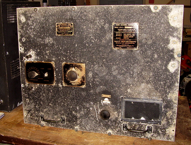
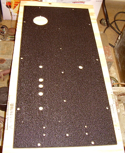
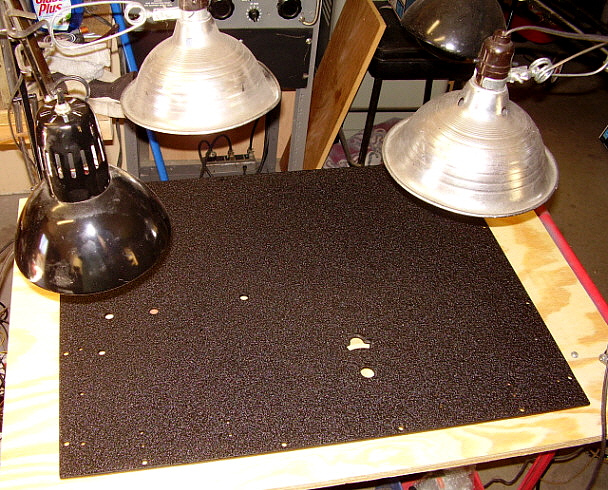
1. Entire repaint will be required. Black wrinkle finish - I'll have to contact VHT to see if I can buy a quart and then thin to spray using the larger paint equipment I have (the type for painting cars.)

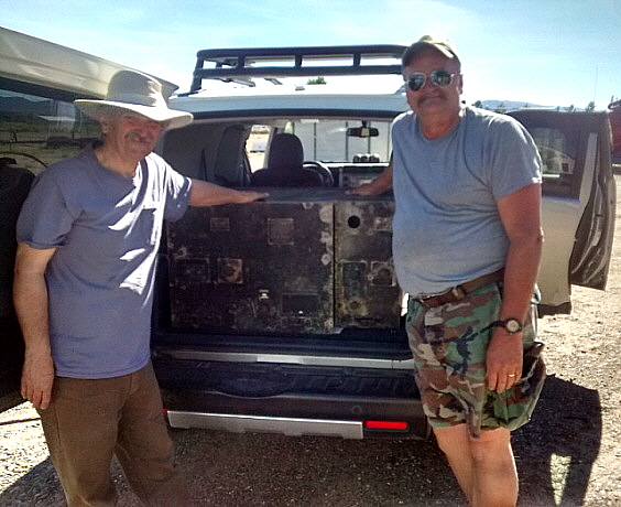
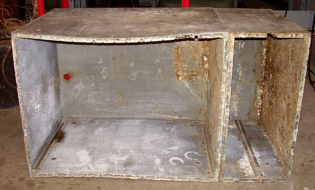
2. Cabinet straighten and repair. Whatever the mounts were, they are missing.

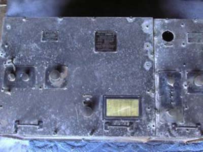
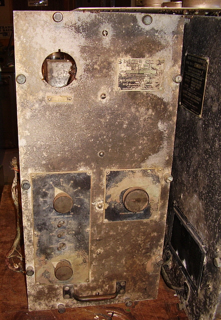
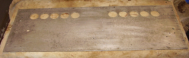
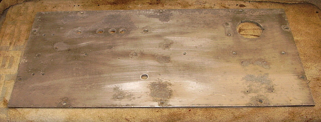
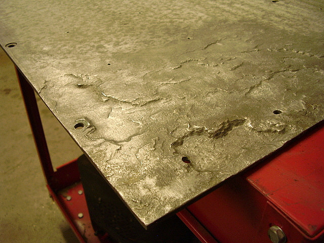
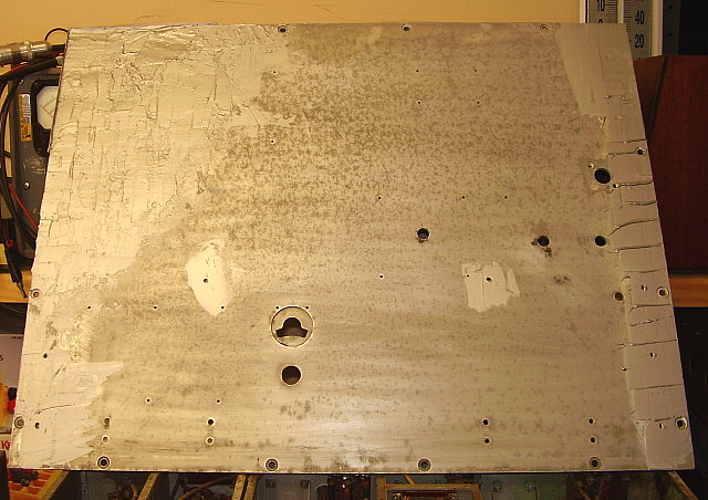
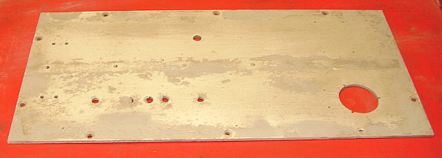
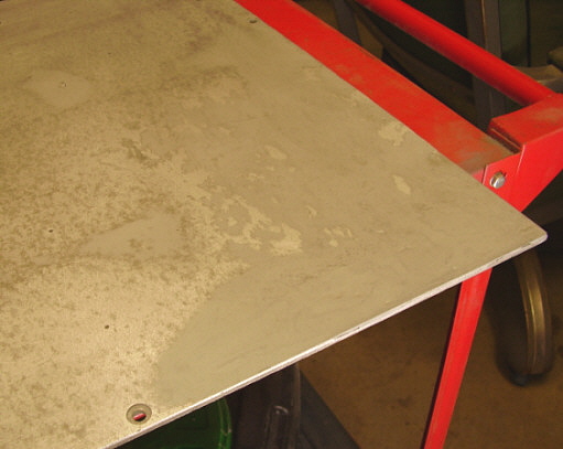
3. Corrosion removal. Most is surface corrosion however some erosion is noticeable on the inside of the front panels where the mounting 
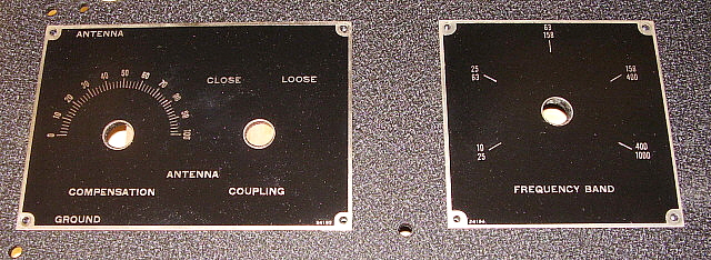
brackets contact the aluminum. Erosion on the back of the Tuner panel is pretty serious.

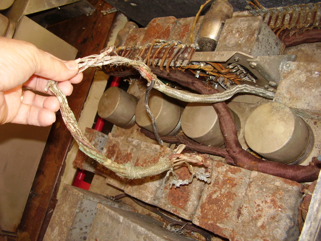
4. Wiring harnesses will require rebuilding. I'll try to use as much of the original wire as possible but it's probably going to be necessary to replace a lot of wires.

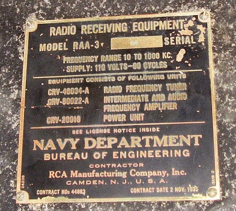
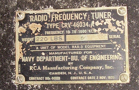
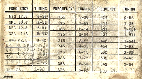
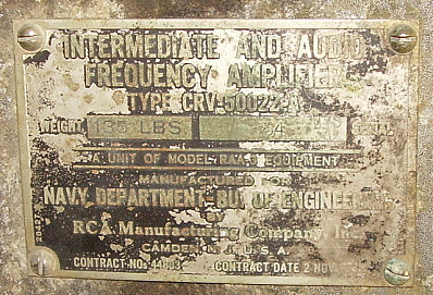
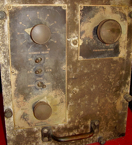
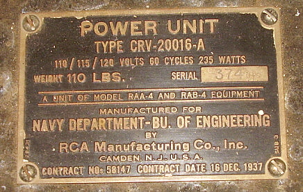
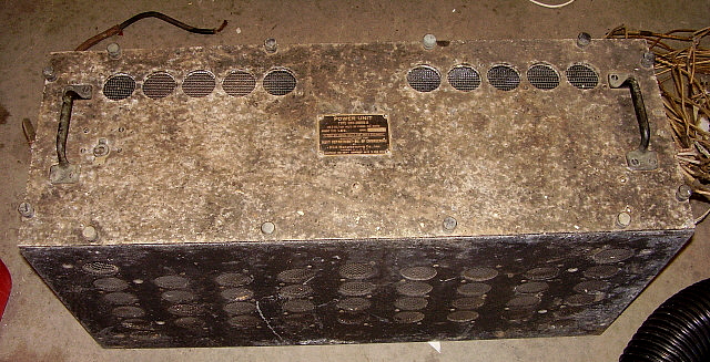
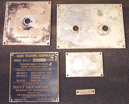
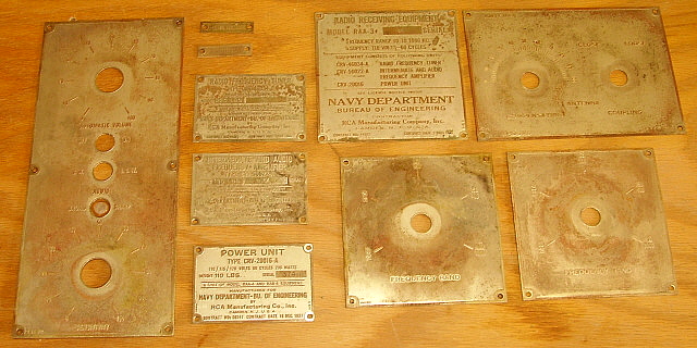
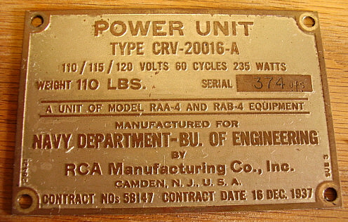
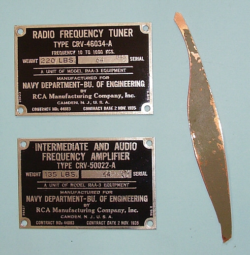
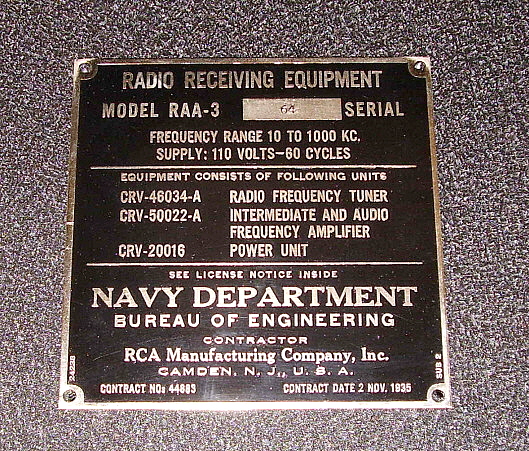
5. Data plates and nomenclature plates need restoring. Fairly easy.

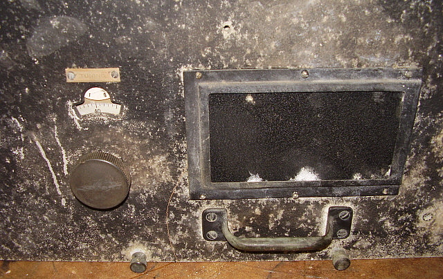
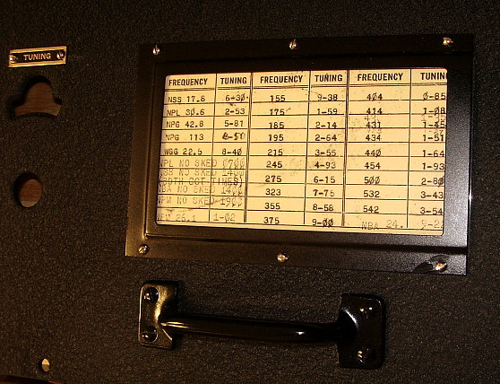
6. Dial doesn't rotate although tuning mechanism works. Shaft turns so dial set screws are probably loose. Dial is held by a threaded boss and nut. The nut was loose.

7. Missing Plate Voltage meter - wiring to meter cut very short. Same Plate meter that's used on the early RBA, RBB or RBC receivers. The 
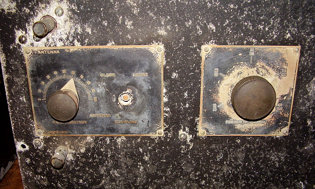
metal housing versions of the meter.

8. Broken shaft on Coupling switch control. I have the original broken shaft and knob. The shaft is made of wood (fiber material) so a replacement is fairly easy to construct.

Here's some of the other problems,...later update notes are in italics.

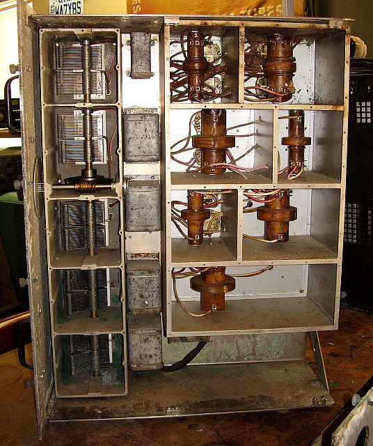
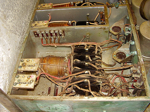
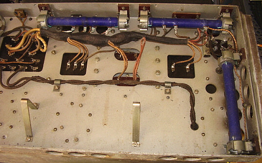
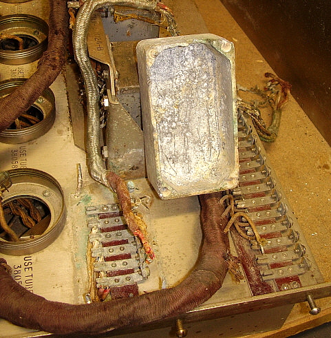
1. Several IF transformers are damaged, some minor,...one major. Appears that mice running around in the compartments broke several wires from the coils to the terminals of the IF transformers. One coil on one of the 238kc IF was bitten into and about 20% of the coil is missing. This one will need to be rewound or a replacement coil from a 200kc IF trimmed to work. Too bad someone removed the bottom shields years ago. 

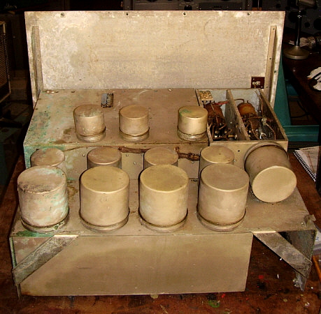
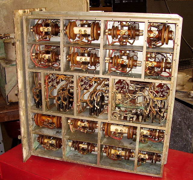
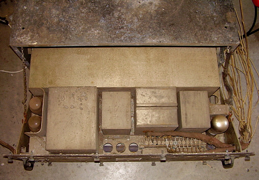
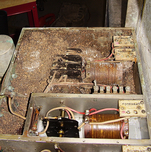
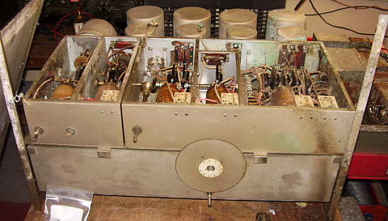
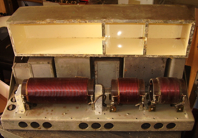
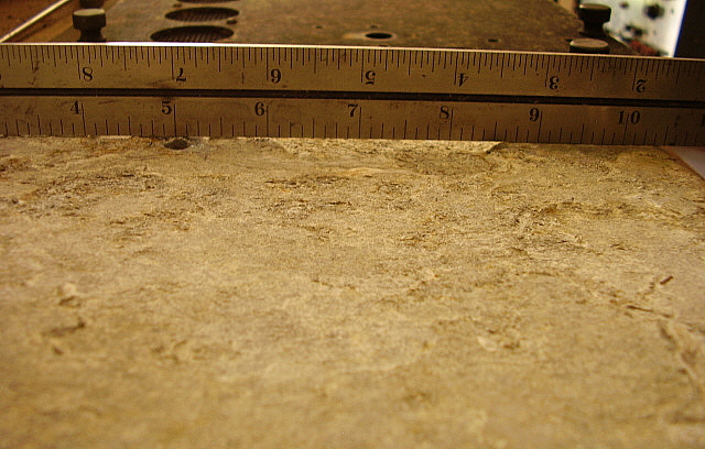
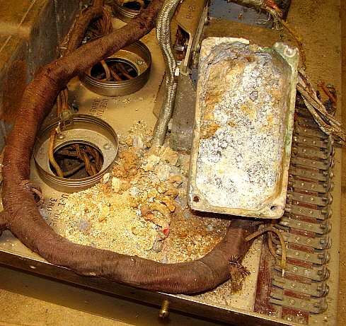
2. Severe nut and seed storage in LO section of tuner - no apparent damage after removal. Used a shop vac (there was a lot of seed/nut debris - see photos below.) One terminal on the bandswitch is broken.

3. IF Bandswitch doesn't rotate - appears shaft is corroded in one bearing - WD-40 and slight pressure defeated the corrosion and the IF Bandswitch is now operational. After the WD-40 had time to seep into the bearing the switch operation is very easy and requires very little effort to effect band changes now.    >>>

>>>  4. Phone jack in IF-AF appears to be missing insulator spacer, wiring shot to jack. This appears to be an output from the detector. It must be for testing since access to this jack would be difficult if the receiver was installed into the cabinet. No access hole in the cabinet where the jack is located. This jack is for alignment and is for installing a detector plate current meter for measuring peak current during alignment. Though the bottom shields are missing, there was a hole in the shield to allow access to this jack.

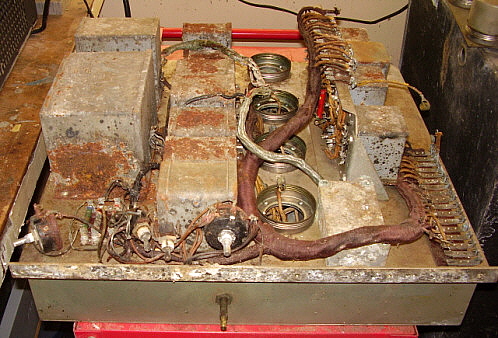
5. Severe surface corrosion on all transformers and chokes (due to steel cases.) These components will need repainting after the corrosion is 
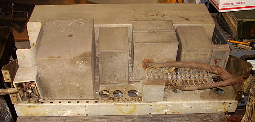
removed. Most of these components are actually bypass capacitors.

6.  Generally, the Tuner and Power Supply are in better condition than IF-AF unit which has the most damage and will be the most difficult to restore to functionability.

The Tentative Restoration Plan - Though a restoration can usually be accomplished without a manual or schematic, it's much easier and ultimately much more complete and accurate with a manual for reference. The first step is to get some documentation (manual found.) During disassembly, all removed parts, including hardware, will be "bagged and tagged" in individual, identified plastic bags. This will be a tremendous help during reassembly since all parts will be easy to find and easy to identify. Since the Tuner and the PS are fairly heavy they will have to be restored in the shop. The PS will be restored first since it appears to be in the best overall condition. The Tuner will be restored next since it's better than the IF-AF unit. Both of these pieces can be worked on in the Summer out in the shop. The IF-AF unit is about 75 lbs out of the cabinet and can be brought into the upstairs lab for repair. This can be done during the Winter, if necessary. Cabinet repair will be done last after the RAA is operational and the Tuner, the IF-AF unit and the PS panels have been restored. If the cabinet restoration ends up being a Winter project, painting may be postponed until it warms up. One caveat,...this plan is subject to change depending on what unforeseen problems are encountered during the restoration process (and we do expect to find many more problems than those listed so far.)

UPDATE to the Plan: December 1, 2017 - As mentioned, the above plan was tentative. I've already changed the plan after some careful thought. Rather than restore each unit, one at a time, I decided to go ahead and do all of the cosmetic restoration work first. This was mainly to be sure that as I progressed through the restoration, I would already know that the 
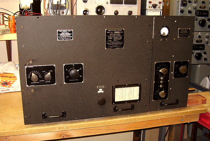
finished RAA-3 was going to "look good." This meant I had to do all of 
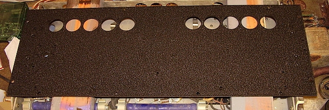
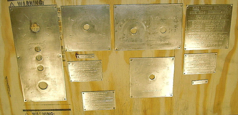
the panel repairs, the painting with black wrinkle finish of the Tuner 
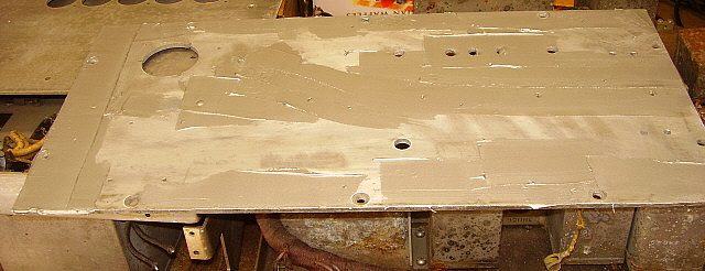
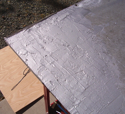
panel, the IF-AF panel and the Power Unit panel. The Tuner panel had significant erosion damage on the back that had to be repaired. This panel is huge and having its wrinkle finish paint job turn out fantastic was a major relief. The added advantage of painting the wrinkle finish on the panels early during the restoration is that the panels can be set aside and the wrinkle paint allowed to fully cure and become the tough, hard finish it can be after a month or two (or maybe a year.) Once all the panels, the panel data plates and the panel hardware are finished and can be set aside to "cure," I'll then do the electronic restoration. Power Unit first because I'll probably need the power supply to restore, test and troubleshoot the Tuner and the IF-AF Unit. Once I have the complete receiver chassis together and operational, then I'll restore the cabinet. The cabinet is extremely heavy and will need to be sand blasted, so this type of operation is probably best done in the summer. Of course, plans always are subject to change and hopefully the changes make sense and will help in the ultimate completion of this restoration.

RAA-3 Disassembly Problems and Some Preliminary Testing

One of the first discoveries was the "Unexpected Cache" shown below. Although disheartening, clean-up, luckily, revealed no problems but many more unpleasant discoveries awaited.


Unexpected Cache - When inspecting any electronic device this is something we dread finding - the apparent infestation of mice. This, however, looked quite different from what is usually found. It appeared to be bird seed, small nuts and mulch, all packed in as densely as possible. Since the debris appeared dry I decided to use a Shop Vac to remove the cache. Luckily, all of the debris vacuumed out and there appears to be no serious damage. Usually there's a lot of corrosion due to mouse urine in a cache like this one but apparently these mice decided they didn't want to use their food store as a latrine. Photo above is after vacuuming. Although this section was covered by a shield, there was a small access area around the terminal strip. This access area should have been covered by the terminal strip-cable metal cover box but this piece is missing. Luckily, the other sections were well-sealed by the shield-cover. This area is the Local Oscillator and part of the Mixer.
Front Panel Dismounting - July 1, 2017 - The first step in disassembly is to dismount the front panels. This will allow easier moving of the chassis of both the Tuner and IF-AF unit. Also, further disassembly can then proceed with the panels off. But first, we have to deal with stuck screws.

Stuck Screws - Even though the chassis and shields are brass and the screws are brass, both still oxidize. I'm finding that some of the screws will break the heads off rather than unscrew. I find that I have to soak the screws in penetrating oil overnight before trying to remove screws. If the screw is still stuck then I apply heat and more penetrating oil. The heat is applied with a soldering iron tip directly to the screw head. The heat-expansion "breaks" the corrosion and helps the oil penetrate which usually allows the screw to be removed without damage. After the screw is removed the threaded hole is "chased" with the proper size tap to clean out any remaining corrosion.

Knob Set Screws - The knob set screws are 8-32 spline socket set screws. None of my spline wrenches fit this spline socket correctly. I had to make a special tool that fit into the spline socket tightly to allow set screw removal. Again, corrosion of the steel set screw in the brass hub of the knob seems to be encountered in every knob and each knob has two set screws. Soaking in penetrating oil overnight is the first step. Then apply heat with a soldering iron tip directly to the set screw. I use a small soldering iron tip that will fit down the barrel to contact the set screw directly without touching the sides of the knob barrel. It helps to alternate between heating and then cooling with more penetrating oil followed by more heat. This procedure was successful for removing the set screws in all but two knobs. These knobs had set screws that defied all the normal removal techniques. Alternating heat and oil over a period of two days with special tools such as a reverse-twist drill and a screw extractor proved useless.

Front Panel Removal - July 5, 2017 - What was necessary to remove the final two knobs may seem unthinkable but the two knobs had to be destroyed in order to remove them from their shafts and allow dismounting of the front panels. I had original replacements for the knobs, so we weren't dealing with irreplaceable parts. I used a Dremel tool and a "cut off" disk to first slice the bakelite off of the brass hub. Once the bakelite was removed, then I used the "cut off" disk to cut away just the set screws. Once most of the set screw itself (two in each knob hub) was cut away, the pressure is released and the hub just slides off the shaft. If done carefully, no damage will happen to the shaft.

With the knobs removed, the next step was to remove the remaining panel screws. Four of the panel screws on the Tuner had been broken sometime in the past. I applied penetrating oil for about two days before trying to remove the remaining screws. I used a blade screw driver that was a very tight fit into the screw slot. Once the blade was in place, I gave the screw driver a couple of hits on the handle to transfer the shock thru the screw. All of the remaining panel screws were removed successfully using this method.

The Tuner panel has some serious erosion on the back where the vertical mounting brackets were attached. In order for the vertical mounting brackets to be fully "flush" against the back of the panel, the erosion will have to be filled. Since the panel is going to be reconditioned to remove oxidation and prepared for painting, it should be relatively easy to use real metal body filler to fill-in the eroded areas. This can then be sanded flat. How it matches the undamaged aluminum remains to be seen when we actually go thru this process.

The IF-AF Unit panel was in good condition although dirty and a bit of surface oxidation. All removed hardware, knobs, tags, handles, tubes, etc. were "bagged and tagged" in plastic bags for easy identification for the reassembly process.

photo left: Tuner with front panel removed. Note the decade tuning dial gear that is driven by the tuning shaft. Note how clean some of the coil boxes are. These were inaccessible to mice and contaminates.

photo right: The IF-AF unit with front panel removed. Although this looks pretty bad, the rust is mostly surface corrosion. Note the foremost bypass condenser has been cleaned just using a brass brush.

Power Supply Panel Removal - July 9, 2017 - Overall there is much less corrosion on the Power Supply. The cabinet and panel had fully screened ventilation holes that prevented any entry of mice or other damaging pests. Inside the chassis is fairly clean and the components appear in good condition with little or no rust anywhere. Underneath the chassis is about the same condition.

I applied penetrating oil on all panel mounting screws and nuts the day before I attempted unscrewing any hardware. This helped a great deal as nearly all screws were easily removed. Only the cable clamp screws proved somewhat difficult but eventually they were removed undamaged.

The photo to the right shows the power supply with the front panel removed. The rust spot on one of the filter capacitors appears to have been caused by moisture trapped by the cloth woven cover of the wiring harness.

photo above: Under the PS chassis showing the power transformer (left,) two chokes, two filter capacitors and the three 100 watt vitreous-enamel coated resistors. Note the power transformer primary terminals and that the twisted AC input wires are connected for 115vac operation. I will change this connection for 120vac input which is closer to my AC line voltage. The three 100 watt resistors all have open windings. Since they can't be rebuilt, I'll have to build replicas that, while they won't look like the originals, will function correctly. The open originals will be kept for future reference.


photo above: The AC Line Filter consists of these three large dual winding inductors and two large paper capacitors and six smaller mica capacitors. Note the shield box and how it isolates each inductor when mounted.

Power Supply Continuity Tests and ACV Tests - July 13, 2017 - The first step to determine if the power supply is going to function is a continuity test of the iron,...that would be the power transformer and the two chokes. Next would be to test the oil-paper filter capacitors for shorts and value. Since we have the rectifier tubes removed, we can actually apply AC voltage to the primary of the power transformer to test its functionability. Since no DC high voltage can be developed, we are only checking the primary, the filament voltage windings, the high voltage winding and the AVC AC voltage winding. If these tests show the transformer produces the correct AC voltages, then it will be left powered for about 15 minutes to see if any heat develops. Without a load, the transformer should stay cool.

Test Results - All iron checked good for continuity. Capacitors checked as "not shorted." There are three vitreous enamel coated, 100W tapped resistors. All three resistors have open sections and therefore have to be rebuilt. These resistors makeup the voltage dividers that provide the proper B+ and negative bias voltages. The AC power cable has to be replaced. This was a shielded cable originally but the cable inside the shield is rotted. The AC power switch tested okay. Someone installed 20A fuses, should be 5A. The AC power switch and fuse block assembly needs partial rewiring that is mainly due to rotting of the AC power cable within the assembly. Replacing the AC power cable will correct the majority of the problems. I haven't tested the coils and capacitors within the AC Line Filter unit yet.

What Needs Rework on the Power Unit - The three vitreous enamel coated resistors need rebuilding. New AC power cable. Rebuild output wiring harness.

July 15, 2017 - Cleaned and reconditioned the AC power switch, fuse board, power cable input and output box. Removed shield from old cable which is soldered to a metal tube that projects out the side of the unit and side of the box. Original wire appears to be 14 or 16 awg 2 conductor with black rubber jacket with shield sleeved over the cable.

July 16, 2017 - Clip-lead connected 120vac to thru the AC line filter to the power transformer. HV winding was over 400-0-400vac. Tube heater winding was 3.0vac. AVC voltage winding was 3.0vac. Rectifier heater was 5.9vac. Voltages were somewhat high because the AC line voltage was 120vac and also there was no load on the windings. Let AC voltage remain on power transformer for about 5 minutes with no changes in voltages and no heat build-up.

July 17, 2017 - I found it was difficult to locate any "new" 14-2 power cable at local stores. However, Home Depot in Carson City did have the correct type cable in stock. Lowe's and True Value don't carry 14-2 anymore and it is difficult to find online except by the 250' roll. I think two-conductor power cable is not going to be an in-stock item much longer.

July 19, 2017 - Miscellaneous Mechanical Work - Removed all broken 10-24 screws that had been used to mount the front panel of the Tuner to the chassis. There were six screw ends that needed to be removed. I had been putting penetrating oil on the screw ends for a few days. The first screw end was long enough that it could be grasped with vice grips and unscrewed. One other screw was just barely long enough to grasp and remove. The next screw had to be drilled and a screw extractor used to remove it. The remaining three were drilled and threaded themselves thru and out as the drill bit grabbed while cutting. When all broken screw ends were removed, I used a 10-24 tap to chase the threads to remove any corrosion. The IF-AF unit didn't have any broken screws but the threaded holes were chased to clean-up the threads and remove any corrosion.

Power Supply - Soldered the original RCA spade lugs to the new AC power cable. This cable connects to the fuse board terminal strip using these two spade lugs. The fuse board also has to output lugs that have to be soldered to the AC Line Filter input wires. I'm going to install new shielding over the new AC power cable. The original was copper braided shield that looked exactly like the shield used on RG-8 coaxial cable, so that's what I'm going to use. The original power cable was about three feet long. Probably when onboard ship the receiver/power supply was connected directly into a wiring box and didn't use a "plug" and the cable was probably just long enough for the connection. I'm going to have a six foot power cable with the braided shield (from RG-8) over it. The original shield was soldered to the AC input metal barrel for the AC cable input to secure that end. The plug-end had the shield secured using a tightly wrapped length of TC that was soldered. This kept the shield in place if the power cable was moved. I'll secure the shield in the same manner but it will have an early-style, heavy-duty two-wire 115vac plug for connecting the power. I'm considering running the PS using a 1:1 isolation transformer with separate ground for the RAA chassis. This would replicate the "floating" AC that was used onboard ships. Another advantage of the isolation transformer can be adjustment of the actual AC voltage (using a Variac) applied to the receiver since our house line runs over 120vac.

Stripping - July 21, 2017 -  I had to do some methylene-chloride* stripping on another project, so I though I'd subject the IF-AF Amplifier panel to the stripper and see what happened. The remaining paint on this panel was so oxidized, it just about fell off when the methylene-chloride hit it. With the paint off, I can see the pitting and corrosion that has occurred on this panel. It's not bad and will clean up with just a little scrapping and application of abrasives.

Missing Hardware - While trying the stripper, I also removed and "bagged and tagged" all of the knurled thumbscrews on all three panels. I noticed that the Power Unit and the IF-AF Amplifier panels were complete with all of their thumbscrews but the Tuner was missing three long thumbscrews and one short thumbscrew. I'll have these replicated, probably by one of my machinist friends. They are black finished brass and use a C-clip to retain the thumbscrew to the panel. Size and threads are 12-24. (Actually, later close examination showed that the "short" thumb screws had the ends broken off. All thumb screws should be the same length.)

Also removed the screens from the Power Unit front panel in preparation for stripping and painting. Since the Power Unit is in good condition, I'll paint this panel now to allow the Black Wrinkle Finish plenty of time to harden. It usually takes minimum two or three days for wrinkle finish to get hard enough to remount parts. Waiting a week is better. Maximum hardness of the wrinkle finish usually takes about 30 days to cure.

July 22, 2017 - Stripped the Power Unit panel. It turned out very nice. Had to do a light sanding with 220 grit to remove the very minor oxidation pits. Once the panel is wrinkle finish painted none of these minor defects will show. See photo below upper photo.

Tried NaOH (Easy Off Oven Cleaner) to remove the green oxidation on the side of the Tuner chassis. This worked fairly well. Required two applications to remove about 80%. Probably one more application will remove the 20% remaining. As far as dirt, oil, grease or any other contaminate, these were gone with the first application.

*Methylene-chloride stripper is very hazardous and must be used OUTSIDE only. Do not use this type of stripper in an enclosed, non-ventilated area. All types of commonly found gloves DO NOT protect your hands. You must use PVA gloves that are layered with Nitrile gloves.

July 23, 2017 - Power Unit - Moved AC input from 115vac tap to 120vac tap. Rechecked the voltages at the power transformer. HV was 415-0-415vac, HTR was 2.9vac, RECT FIL was 5.5vac, AVC FIL was 2.8vac. Again, this is with no load. The circuit normally has a 1144 ohm 100 watt resistor that is a constant, "dead" load on the B+, so I'm sure once everything is up an running the voltages will be much lower and probably in spec.

Calculated all wire wound resistor dissipations and designed replacements for the three open WW 100W resistors. These replacements will "plug in" to the mounting clips as the original resistors did. Unfortunately, it's impossible to repair the original resistors and the only acceptable method is to design and build replicas that fit into the original clips and provide the same resistance and dissipation. The replicas will have terminals for mounting individual WW resistors and will be built on a strip of high-temp delrin. Though they won't look like the originals, they will fit exactly and operate correctly. The original WW resistors will be saved for future reference.

IF-AF Amplifier - Panel oxidation was cleaned up using 220 grit sand paper. Some of the oxidation/corrosion areas are pretty rough and may require further treatment and perhaps minor metal filling. The oxidation/erosion of the metal may be due to dissimilar-metals with salt residue and moisture acting as an electrolyte. The erosion is only where there was contact of the aluminum with nickel-plated brass parts such as the chassis vertical brackets used in the Tuner or the contact of the aluminum panels and the nickel-brass cabinets.

Had to drill out two broken 4-40 screws on the IF-AF panel. Chased all 4-40 threaded holes with a tap to clean threads of any oxidation.     IF-AF Panel photo lower right.

Tuner Panel Backside - The photo to the right shows the severe erosion that is located on the back of the Tuner panel at the upper left part of the panel. As can be seen by referencing the straight-edge, the erosion in some areas is almost halfway thru the panel thickness. As mentioned above, this erosion is not everywhere. It is only where the nickel-plated brass made contact. Some areas are very minor and clean up with 220 grit sand paper. The area shown in the photo is the most serious. Some of the residue found when dismounting the front panels appeared very similar to "baking soda" which makes me think that maybe it's salt residue from "salt-air" of the sea that was "trapped" over the years and then had time to react with the moisture of the storage environment. Salt water can be very corrosive. Well, regardless of what caused it, the question is how to repair the damage?

After a thorough cleaning, I'm going to try using USC All Metal Aluminum body filler. It is a catalyst-activated paste filler used in autobody repairwork. It should be strong enough and if the area is ultra-clean, it should adhere quite well. When it sets up, it can be sanded to be flat with the non-damaged surface. Since the non-damaged aluminum will also be sanded and the all metal filler is also aluminum silver in color, hopefully the repairs won't be too conspicuous.

As mentioned somewhere further up this page, the back of the Tuner panel has to be fairly flat so the mounting against the two vertical support brackets aren't distorted or bent when the mounting screws and nuts are tightened.

July 27, 2017 - Tuner Panel Work - Three broken screws had to be drilled out. 4-40 tap used to chase threads afterward. On all three panels, all broken screws have been removed and all threaded holes are now open with the correct threads. Stripped Tuner Panel of all remaining paint using methylene-chloride. Wet sanded panel back and front to assess condition. Front of panel is very good with only a few corrosion spots that aren't serious. Rear of the panel is in good condition except the upper left area (viewed from rear of panel.) Wire brushed corroded area and it cleans up but will require a heavy-duty rotating steel wire brush to remove all corrosion and residue. I'm going to use USC All Metal Aluminum Body Filler to "level" the rear side of the Tuner panel.

Power Unit - Replica Wire Wound Resistors - Checked Mouser and all resistors required are in stock. Order soon. Checked measurements of 1" copper pipe end caps to use for end caps on replica resistors. These are virtually the same diameter and will work perfectly. Bought six caps to build the three WW resistors needed. Test fit into mounting clips and the fit is perfect.

July 29, 2017 - Ground post was causing some interference with thorough cleaning of the Tuner Panel. This post was a "press-fit" with serrations to prevent it turning. On the back side, a 10-24 screw and internal-tooth lock washer also secured this ground post to the panel. Used a large socket to act as an anvil with a clearance hole for the ground post. With a 10-24 threaded into the post, I tapped the post out of the panel with a small hammer hitting the top of the screw. No damage to either the ground post or the panel. Ground post and screw were put into the "Antenna and Ground Post" plastic bag and the bag placed in the box with the other bagged Tuner parts.

Front Panel Body Work

The erosion damage on the back of the Tuner panel was something I've never encountered before. The repair using USC All-Metal Body Filler was also a first.

Aug 3, 2017 - Made it to Sparks, Nevada and to Summit Racing to purchase a quart of USC All-Metal Body Filler, which they had in-stock. Also, purchased three cans of VHT Black Wrinkle Finish for painting the Power Unit panel and the AF/IF panel. Tuner panel will be painted after the body filler has successfully repaired backside of that panel.

Delay - A major delay in our restoration work is due to re-laying out the shop to have more shelving for storage and moving an eight-foot work bench to a better location that allows more work space and an "in shop" test and repair bench with full lab equipment. A couple of weeks delay will end up with a much easier environment to work in.

Aug 25, 2017 - Shop layout is done.

September 1, 2017 - Started to clean up the erosion damage on the Tuner panel. I used a rotary wire brush powered by a handheld electric drill. This dug-thru the loose powder and eroded metal to show bright aluminum underneath. The photo to the right shows the worst area of the Tuner panel backside (the upper left corner as viewed from the rear.) With the metal bright, the damage becomes very apparent and visible. Note in the photo that further into the panel area that there is no damage and the metal is nice and flat.

September 5, 2017 - Hal Layer KK6HY generously sent me an original RAA manual. Thanks Hal! The new B&W header photo is from this manual.

Oct 6, 2017 - I thoroughly went over the entire eroded area with a new conical wire brush to get into every corner of the damage. Afterwards, I cleaned the entire area with denatured alcohol. USC Body Filler tomorrow.

Oct 7, 2017 - Applying the USC All-Metal Body Filler - All other projects were out of the way and today was going to be a warm day, so I had planned ahead to do the aluminum body filler (ABF) on the rear panels.

The ABF is a thick aluminum-filled paste to which an amber liquid catalyst is mixed to activate curing. Instructions indicate that about a "golf ball" size amount of ABF takes about 12 to 15 drops of catalyst. Working time is less than 10 minutes. I spread the mix with a disposable plastic putty knife. In the upper left corner the erosion had attacked and thinned the edge. I made a masking tape "dam" to keep the ABF from running over the edge. The erosion damage was so deep that four coats of ABF were needed to get the entire area somewhat level. However, minor erosion "blemishes" could be covered with just one thin coat. The ABF does set-up fairly fast but doesn't "cure" to its full hardness for several hours. I let it set overnight which was long enough for full curing. Both the Tuner panel and the IF-AF panel had ABF applied to erosion damaged areas.


photo above: IF-AF panel. Only minor damage on back side covered with one coat of ABF


photo above: Two coatings of ABF in damaged area of Tuner panel
photo right: Finished with four coats in damaged area. Only one coat was necessary on the minor damage on the right side of the panel

Oct 8, 2017 - I checked the ABF after letting it cure overnight. It was H-A-R-D! In fact, I tried 220 grit sandpaper by hand - just as a test. It hardly did anything - just scuffed the ABF and didn't remove anything significant. Later in the day, I decided to try again. This time with 60 grit on a hand sander (that's what the ABF instructions recommend.) What a difference. This removed the excess ABF very easily. The seemingly rough removal was accomplished on the Tuner panel in about 15 minutes. The surface was very flat feeling but still had some appearance of not being level. The next sanding will be with 120 grit but, the next sanding session will be outside. What a mess! Aluminum powder everywhere in the shop. I thought it was just going on the floor, which I kept sweeping up every few minutes. The fine powder seemed to travel about six to eight feet in all directions. Since it's somewhat conductive, I had to do a thorough clean up.

After this initial sanding, the back of the Tuner panel looks very good. After more sanding I might have to apply a minor "touch up" fill for small spots that I missed. Also, some of the holes in the panels were filled in with the ABF. I'll have to drill out the clearance holes and drill and re-tap the threaded holes. In all, I should have the Tuner panel and the IF-AF panel done in a few more days.

Oct 9, 2017 - Continued with sanding the ABF. Shown above is the repaired area where the Tuner panel was damaged most severely. Although the color doesn't match, the surface is smooth. Shown to the left is the IF-AF panel that had much less severe erosion but still benefited from some minor ABF followed by sanding. All sanding so far has been with 60 grit. I'll probably do a touchup minor fill and then final 120 grit sanding. >>>

Applying Black Wrinkle Finish Paint

"Acres of Wrinkle Finish." That's what I thought about when painting these enormous panels. The system I use for successful wrinkle finish application is one that I've developed after years of "trial and error" and crummy-looking paint jobs. The wrinkle finish painting procedure described here is one that "works every time." Without a doubt, the RAA-3 Tuner Panel is the largest panel I've ever painted with wrinkle finish and I was extremely relieved when all three panels turned out perfect.

Oct 9, 2017 (cont.) - After the panel repair work is finished, I'll be going on to the wrinkle finishing even though it's Fall and the weather is getting cooler. In preparation of the painting phase of this project, I'm going to have to rebuild my wrinkle finish heat applicator. I used to use 100W incandescent lamps in aluminum bell-reflector clip lamps. Two or three of these would provide enough heat to activate the wrinkling process. Most of my incandescent light bulbs are bad and 100W replacements are getting difficult to find. I decided to go with "brood lamps" instead. These are "heat lamps" that are rated at 250W. Since heat is the objective, they are incandescent filament-type lamps and will provide the heat necessary for wrinkle finishing. I purchased the brood lamps at Tractor Supply. Also, when I actually will be doing the wrinkle finish heat application I will be standing by with a handheld heatgun to help activate wrinkling in problem areas like corners or edges. Although the lamps might get all of the panels to fully wrinkle, having the heatgun ready can speed along the process and assures a full wrinkle on the entire panel.

Oct. 17, 2017 - Another delay. This short delay came in the form of a very nice RBA-1 receiver that needed restoration. This project will probably "eat up" about three or four weeks but the RBA-1 is all original and complete so it is well-worth the time involved.  Turned out very nice.

Nov 19, 2017 - Built the heat lamp station today. Has a 24" x 36" piece of 3/4" plywood mounted to the top of a roll cart. There are two articulated desk lamps mounted in opposite corners of the wooden top. The lamps are 250W brood lamps. Just about any combination of desk lamp movements produce a good heat pattern for various shapes of panels. I'll have to test on a scrap piece first and, if all is okay, I'll proceed to paint the RAA panels after they are prep'd.

Nov 20-21, 2017 - Drilled out ABF where it had filled some of the panel holes. Where the holes were threaded a tap was run thru the hole to "chase" the threads. The most difficult part to clean of excess ABF were the recessed 0.5" diameter relief holes for the retaining clips for the panel thumb screws. I looked in several sources for a .25" diameter bit with a 0.5" cutting shoulder but nothing could be found anywhere. Finally, I decided to just use the .375" diameter AL/OX cylinder grinding tip and a Dremel tool to remove the excess ABF from the recessed holes. This actually worked pretty well. Final clean up of the recessed holes was done using a 0.5" diameter end-mill - by hand - followed by cleaning the area with a brass wire brush.

Nov 22, 2017 - Panels were cleaned up in preparation for painting. Consisted of light sanding followed by lacquer thinner wash. Since there was virtually no wind today, I applied the paint outside then brought the panel into the shop and put the panel under the heat lamps. Most of the problems with painting wrinkle finish are due to not enough paint applied over the entire surface. This results in uneven wrinkling or "stripes" in the wrinkle pattern. The other problem is not enough heat to induce the wrinkle process. This results in uneven wrinkling or lack of wrinkling in some areas. I always apply four "double" coats. Each part of each double coat is applied first in one direction and then in the opposite direction. Each of the complete double coats are applied in different directions with about a one minute wait between double coats. This reduces the possibility of stripes or uneven wrinkling. You have to be careful to not apply so much paint that it runs or sags. I usually shoot the paint with the panel lying flat. After the fourth double coat, the panel is taken into the shop and put under the heat lamps. I adjust the lamps so they are about 12" to 15" above the painted panel. I also have a hand-held heatgun that I use to continuously apply heat to the entire panel. I evenly go over the entire panel but I especially watch the edges and corners since these have a tendency to not wrinkle. The wrinkle process takes about 7 or 8 minutes to start on a large panel like the RAA panels. Once the wrinkling starts, I continue with the heat gun and sometimes I'll move the lamp positions to apply heat where wrinkling hasn't started yet. It takes another 5 or 6 minutes for the entire panel to wrinkle. I then turn off the heat lamps but continue to "wave" the heatgun for another minute making sure that edges and corners have all wrinkled. Do not hold the heatgun in one spot, too much heat will "gloss" the paint and ruin the wrinkle. Keep the heatgun moving all the time. With the heat removed, I let the panel cool down. I don't even move it for at least 30 minutes. I successfully wrinkle finished the IF-AF Unit panel and the Power Unit panel today.

Nov 23, 2017 - It's appropriate that I painted the Tuner panel on Thanksgiving morning. I had really been concerned about the wrinkle finish on the Tuner panel because it's huge - "acres" of wrinkle finish. I modified the heat lamp station by adding two more lamps. These were equipped with 100W incandescent lamps. The paint would be heated with two 250W brood lamps and two 100W incandescent lamps plus the hand-held heatgun. I applied four double coats of black wrinkle to the Tuner panel outside then moved the panel to the heat station. It took about 6 minutes of heat to get the wrinkle started. Full wrinkle in about another five minutes. The wrinkle on all three panels was thick and even with lots of texture.

However, even after a day of curing, the wrinkle will still be somewhat soft so I won't be mounting anything to these panels for quite a while. I usually wait at least a week to allow the wrinkle to fully harden. A month is better. Who knows how long it will be before these panels are once again mounted to their chassis? How about one year? 

Photos of the wrinkle finished RAA panels below.

photo left: IF-AF panel after painting with VHT Black Wrinkle Finish. By comparing this photo to earlier photos of this panel without paint it becomes obvious how many defects and surface problems the wrinkle finish texture hides.


photo right: Tuner panel after painting with VHT Black Wrinkle Finish. The panel is still setting on the heat table (lamps are off, of course.) Note the lamps. The two dark color bells have the 250W brood lamps. The two aluminum bells have 100W incandescent lamps installed. Besides the four lamps, a hand-held heatgun is used to induce the wrinkle. The "key" to successful wrinkle finish painting is plenty of paint and lots of heat.

photo left: The Power Unit panel after painting with VHT Black Wrinkle Finish. Not only does the wrinkle finish texture hide minor defects in the metal surface but, as the paint cures, it becomes much "tougher" and has the ability to resist some types of abuse. The VHT paint seems to attain its full cure in about one month. One can carefully handle the painted panel within about 30 minutes after the wrinkle has appeared. This is about how long it takes for the paint to "cool down" from the heat applied to induce wrinkling. After one day of curing, the paint is easy to handle but it's still relatively soft. If anything is mounted to the panel, the paint will compress and sometimes "squeeze" out from under a screw head or a mounting flange. I usually wait a minimum of a week before mounting any parts. A month is better. These panels set around for a year - nice and hard now.

Restoring the Data Plates

Although this section seems rather long, the data and control nomenclature plates are just as important as the wrinkle finish paint. The data plates might seem small and probably not too difficult to do but, of the latter, just the opposite is true. Proper restoration is tedious work that seems endless but the final result is worth the effort.

Nov 29, 2017 - All of the data plates and the control nomenclature plates were in pretty poor condition. Lots of wear is apparent on the band switch plates. Close inspection of these plates revealed that the rear of each plate is nickel-plated. It also appears that the fronts might have been nickel-plated. This would result in the data and control plates being black background with silver lettering. Maybe a thorough cleaning might reveal some remaining nickel. If not, I'll be stripping off the remaining paint on the plates and hopefully there will be nickel under the paint and that would confirm that the plates were originally black background with silver letters. I do have all of the materials to nickel-plate these pieces, if that's original. NOTE: Earlier versions of the RAA receiver used silver background with black letters on the ID plates and black background on the control plates. You can see this in the B&W photo from the manual (header photo) and on the photo of the RAA-2 on the U.S.S. Texas. Also, note on the Texas RAA-2 that the Meter (Plate Voltage) tag and the Tuning tag appear to be silver lettering.

Nov 30, 2017 - Brass brushed the IF-AF data plate. It's nickel-plated back and front. The band switch plate from the IF-AF unit looked brass but the back was nickel-plated. I used NaOH to clean corrosion but leave any plating unharmed. Most of the brass color disappeared and the plate looked more nickel color. I'm pretty sure I'll have to re-nickel plate all of the tags so they will end up consistent in their nickel color. First I'll strip any paint left so the tags. At that point, I should be able to tell actual condition of the tags.

Dec 1, 2017 - Stripped all of the data plates of remaining paint. Used methylene-cholride and stripped outside, with proper gloves. All paint was easily removed. Some plates needed a little bit of brass wire brush application to remove all paint. Washed with water followed by drying and then washing with lacquer thinner.

Data Plate Photos - Photo upper-right shows some of the data plates front and back. Nickel plating is obvious. Photo below-left shows the data plates with all of the paint stripped. Again, it's apparent that the data plates were nickel-plated front and back. The photo below-right is a close-up of the Power Unit data plate. Although the lettering looks brass, note the upper right mounting hole showing nickel. Since the lettering was always exposed, the nickel probably oxidizes to this brass color. When cleaned with NaOH, the nickel color begins to show through the oxidation (see June 17, 2018 for notes on further cleaning.)

Dec 13, 2017 - It's been very cold with morning temps of 10F or lower. Shop temp is about 32F unless I turn on the Reznor heater. Too cold for much restoration work. However, I did locate my Nickel Sulfate solution and my pure Nickel anodes for doing the electroplating of the data plates.

The plating process runs a small electrical current through the Nickel Sulfate solution from the anode to the piece to be plated. The current flow removes molecules of the anode and deposits them on the the piece that is being plated. It doesn't take very much voltage (1 to 3 volts) to have enough current flow. Proper voltage polarity has to be observed so that the current flow is from the nickel anode (+) to the plated piece (-.) Too much current (voltage too high) will "bubble" excessively or even "foam." This will turn the plated piece black. The bubbles from the current flow should be about like the bubbles in a glass of champagne. Not enough current (no bubbles) and the piece will take a very long time to plate or will plate unevenly or not at all. The bubbles are of course a gas and that gas is released during electroplating. The sulfate gas will cause headaches with a mild exposure. With more severe exposure nausea can result. All nickel plating should be done outside (brrrr.)

The plated piece has to be very clean. Anything showing on the surface will also show through the plating. I don't want to "polish" the data plates because the original lettering was matte nickel finish. The cleaning can be done chemically with either NaOH or with Sparex cleaner.  >>>

>>>  The actual plating only takes a few seconds to see the nickel color on the plated piece. However, this is a very thin coating. To achieve a good thick plating will require several minutes for small pieces like the data plates. Maybe five minutes for the larger data plates. The solution, the anode and the plated piece should all be at least 70F,...warmer is better and plates faster.

Buying Nickel Plating Supplies - I bought everything at an old jewelry hobby shop in Reno many years ago (late-eighties.) At that time, the solution was sold by the quart. Anodes were mounted on stainless steel tangs. I've recently looked and there are several sources on the Internet that sell all of the nickel plating supplies. If you want something local, try to find a shop that sells supplies for making your own jewelry. Otherwise, go with the Internet.

Winter Diversion - March 10, 2018 - A friend gave me an old Zenith tube caddy that was supposed to have a good selection of metal tubes for the BC-344/342 family of receivers. When I got home and inspected the caddy's contents I was surprised to find a meter in with the tubes. The meter looked promising in that it had a metal case. It looked even more promising when I turned it over and I saw the scale was 0 to +250vdc. The face of the meter was full glass with the zero mechanism mounted in the glass. The meter was exactly like the Weston 506 Navy meter needed for the RAA-3. Well,...maybe not exactly. The scale face is white and the meter is made by Simpson. But, other than those two minor points, it is exactly like the missing meter for the RAA. It actually is a later replacement meter for the Weston 506, so the fit is perfect and it's already scaled for 0 to +250vdc. This means it can be connected up directly to the RAA IF/AF unit harness. This was the last major part that I was missing. Of course, if the original type Weston/Navy 506 meter turns up, that would be great. But, for now, we have a meter that will function correctly and is a correct "replacement part." 
Jan 20, 2019 - A Weston 506 USN 0 to +250vdc meter has been found.

June 17, 2018 - Finally, back at it (it was a cold Spring this year.) I started cleaning all of the data plates in preparation for nickel plating. The only thing that seemed to cut the corrosion was to just go ahead and "brass brush" the data plates. The tags will need a chemical cleaning before nickel plating. Also, "brass brushed" the handles in preparation for painting. Although I had thought about using "off the shelf" paint, I decided to go ahead and use my black nitrocellulose lacquer which was probably what was used originally for the handles and the chart frame. The knurled thumb screws are going to be given a "black patina" treatment. This is a chemical oxidation process that turns brass black. It's probably close to what was originally done to treat these screws.

Nickel Plating Data Plates

July 4, 2018 - Got everything set-up to nickel plate. The first tag turned out splotchy and gray. I tried another tag with just about the same results. Turns out I had the polarity backwards. Hmmm. The good thing is I didn't "electro-strip" the tag material because I had the current so low. I'll try again tomorrow using the correct polarity. It had been many years since I nickel plated anything but you'd think I'd remember how to connect up everything.

July 5, 2018 - Plated six of the ten tags. Minor problem with the shallow plastic container I'm using for the Nickel Sulfate solution. The tag being plated has to be horizontal to be fully immersed in the solution. This puts the center of the tag furthest from the anodes. The centers on two of the larger tags are pretty thin on the plating. For the remaining tags I'll use the 4000ml beaker which will allow for vertical placement of the tags while plating. This should then allow the center of the tags to plate better.

July 6. 2018 - The nickel plating set up is shown in the photo to the right. Pretty simple. Adjustable power supply, Pyrex beaker, two nickel anodes and the nickel sulfate solution. The actual plating has to be done outside. I waited until afternoon so I would have a good breeze to keep lots of fresh air supplied. On the average I used about +3 to +4vdc and 400mA but that depended on the size of the tag. Larger tags can take more current. The small "TUNING" and "PLATE VOLTAGE" tags only take about 250mA at about +3vdc.

July 6, 2018 (cont.) - The 4000ml beaker really made the difference. I was able to keep the tags vertical and that allowed for an even plating. I went ahead and re-nickel plated all of the tags I had done the day before. This was to have all ten tags have basically the same finish. The AVC tag on the IF Unit was too large for  placement in the beaker so I had to plate that tag in the shallow plastic container. I oriented the anodes to equalize the plating. I also had to position the tag to have it as close to vertical as possible. I could only keep about half of the tag in the solution. I had to keep moving the tag to make sure the plating was even. The end result was fine as can be seen in the photo to the left.

One has to remember that most of the nickel surface is going to be painted over. Only the raised nomenclature and scales will show silver through the black paint. There were two reasons for the nickel plating. First was to have a corrosion resistant surface that allowed the background paint to adhere well and second to have "silver on black" nomenclature and scales for the best visibility.  
 

Black Paint Fill on Data Plates

July 26, 2018 - This is one of those processes that has to be experimented with to develop a method and tools that work. First, the original process for manufacturing these data plates can't be duplicated because the background paint was originally applied between the etching process and the photo-mask removal. That meant that the lettering was protected and removal of the photo-mask didn't affect the background paint. This resulted in the lettering showing perfectly in the nickel-plated silver color. Since these data plates don't have the benefit of the photo-mask when they are painted, that paint goes directly onto the lettering as well as the background. The process that has to be developed is how to successfully remove the paint from the lettering surface without damaging the nickel plating and without damaging the paint-filled background.

Now, the things that don't work,...any type of squeegy, whether metal or rubber will not successfully remove the paint from just the lettering surfaces. Since the tool edge is dragged along the "high points" of the data plate, the removed paint residue tends to "roll" under the edge and ends up ruining the background paint surface. Next,...using lacquer thinner and a flat pad surface to chemically remove paint from the "high points." This "almost" works. Usually though enough removed paint is mixed with the thinner and somehow contacts the background paint. Sometimes excessive pressure when rubbing the data plate across the thinner pad will deform the plate and allow the background to contact the thinner pad removing the paint there. Any abrasive such as 400 grit AlOx paper will scratch the nickel plated surface. Any steel tools will also scratch the nickel.

This doesn't leave too many methods of removal that aren't super-labor intensive. I've come to the conclusion after trying many different methods now (and also reviewing what I've done in the past when restoring etched metal tags) that the only safe method is the use of home-made copper tools to "scratch off" the paint from the "high points" of the data plate. Copper tools will not scratch the nickel plated no matter how hard you press. The tool must present a sharp, bend-resistant edge to maintain good control of the paint removal process and limit any collateral damage to the paint background. Any minor defects afflicted on the paint background can usually be touched up afterwards.

July 29, 2018 - Making the Copper Tool - The copper tool is made with the shape of a very shallow "S" curve which allows holding the tool like a pencil but having the tool edge at a good angle for scraping. The copper material is .190" thick and the working edge is sharpened. Both ends are sharpened with the long end having the .190" thickness but the other end is reduced thickness to .060" for lines and scales. Since the copper is very soft compared to the nickel plating, it won't scratch the nickel at all. However, because of the soft nature of the copper, the tool must be sharpened often (every few letters.) I use a small flat file to sharpen the working edge. See photo below showing tool with two completed tags.

July 31, 2018 - Success on Background Paint Removal - This is tedious work but it seems to be the only method that ends up with the data plate looking perfect. The background paint is black nitrocellulose lacquer. I use the Preval spray system that has replaceable sprayers. A glass jar holds the mixed lacquer (Preval sprayers are available from Home Depot.) I sprayed two data plates at first to develop a removal system that would work. The copper tool allows accurate paint removal from each individual letter or number comprising all of the nomenclature on the data plate. I had to use a head-mounted magnifier to actually see "close-up" what I was doing. This is slow and exacting work. There are no short-cuts. On average, it took about one and a half hours to finish an identification tag while the control nomenclature plates took about half an hour. The ID plates are very dense with lettering and numbers, so that's why the time required was longer than the control nomenclature plates. Only ten minute paint removal sessions are recommended since eye fatigue seems to result in minor mistakes.

While removing the paint, you have to continuously brush off the paint residue. Also, the copper tool MUST be very sharp. Usually about three or four letters can be finished before the tool needs to be resharpened. Just a couple of file strokes is all that's necessary for sharpening the tool's cutting edge. When paint removal is completed then the data plate is wiped with a piece of soft flannel cloth. Any touchup necessary for minor scratching of the background paint can be accomplished with either a black Pilot pen or, if it's a deep scratch, then thinned lacquer can be applied using a toothpick. Be sure to only apply the lacquer in the scratch, not around it.

Aug 10, 2018 - To sum it up - All ten data plates finished on August 10th. I absolutely hate that this part of the data plate restoration process turned out to be so tedious, so crude and that the time involved was so excessively long. I thought there might be an elegant, simple way to remove the paint but this scraping process is the only method that I've found that results in an excellent appearing data plate. BUT, the copper tool is the key to success in this primitive but effective process.

photo top left - Data plates for the Tuner and the IF-AF Unit after restoration. Copper tool shown to the right of the tags. The shape of the tip shown is how the tool initially started out. By the third data plate the tip was much smaller and had a more pronounced roll-off on the top. This allowed better sighting of the letter to tool contact point with more accurate control of the paint removal.

photo top right - This was the most difficult data plate to restore. It's large size and density took about three hours to remove the paint from the lettering. This data plate was photographed setting in place on the black wrinkle finish of the Tuner panel.

photo bottom left - The control nomenclature plates for the Tuner. The scales are somewhat difficult to do because of the fine index lines. The .060" edge of the copper tool is used for removing paint from the lines. These two nomenclature plates were photographed in place on the Tuner panel.

photo right - The control nomenclature plate for the IF-AF Amplifier. Although this is the largest of the ten data plates it wasn't difficult because the lack of density for the lettering and scales.

Finishing the Front Panel(s) Work

Painting the Panel Hardware - The hardware consists of the grab handles, the tuning chart frame, the various panel mounting screws, the data plate screws and the knurled thumb screws.

August 15, 2018 - Tuning Chart Frame was given a black lacquer paint job. I'm using the Preval sprayer system so I can spray my own mix of nitrolac+thinner. Paint has to be thin in order to spray as a mist. Too little thinner and the spray will have droplets that result in orange peel or lumps. Usually a proportion of 1:1 works okay. Two parts thinner to one part paint is pretty thin but can work okay in hot weather. 1.5 thinner to 1 paint seems best for the Preval type sprayer. Tuning Chart Frame mounted with six 4-40 round head brass machine screws .250" long. The screws are nickel-plated (as original.)

September 23, 2018 - It took quite a while to decide what color the grab handles were. Inside the shop, the handles looked dark bronze color. Outside in sunlight, the handles looked black. Close examination seemed to indicate that the handles were bronze color (maybe the original color from the parts supplier) but did have black paint on them that had mostly worn off. I went ahead and painted the handles black nitrolac along with the mounting screw heads. After the paint had set for a while, the handles were mounted to the panels.

All of the data plates were mounted with 4-40 x .250" round head brass machine screws that were nickel plated. These were either NOS or excellent used screws. These screws were .062" longer that the originals. I had to use the longer screws because of the better condition of the threads further into the panel. Other than the length, the NOS screws are exactly like the originals. On the IF/AF Amplifier panel four 4-40 holes were worn or enlarged enough that the screws couldn't be tightened. On these four holes, I peened the hole rim with a center punch to reduce the diameter and allow the 4-40 screws to tighten.

September 23, 2018 - Tuning Dial - This is a dual dial system that has a 0-10 dial on the main shaft and a 0-100 dial that is gear driven from the main shaft. The 0-100 dial rotates on a fixed shaft attached to the Tuner chassis. The 0-10 dial was slipping and loose when I took the RAA apart. This problem was caused by a missing Woodruff key that keeps the 0-10 dial "locked" to the main shaft. Since the key was missing, eventually the 0-10 dial loosened and began to slip. I think the key was originally a small tab that fit into the key notch and locked the dial to the main shaft. It appears that the small tab was broken off and that's when the dial began to slip. I needed to make another key which can be just like a Woodruff key and not necessarily attached to the 0-10 dial. I just made a .030" square metal piece about .090" long to act as the key. To synchronize the two dials I had to set the tuning condenser to full mesh. Then the 0-100 dial was set to 0 and the 0-100 drive gear installed onto the main shaft. The key was installed to "lock" the gear to the main shaft and then the 0-10 dial was installed with it set to 0 and the locking nut tightened. The main shaft has to be held with vise grips to keep it from tuning while the locking nut is tightened. Once mounting was complete, then the drive gear and the 0-100 dial gear were given a light coat of grease. With a test knob installed, tuning was smooth and effortless. Synchronization was good.

September 24, 2018 - Ground Terminal - This fitting needs to be press-fit back into the panel. The base has serrations to assure a good electrical connection to the panel. The base/standoff needs a patina finish and also needs to have the threads "chased" since the thumb screw doesn't thread in all the way. Patina-oxide treatment for correct finish. Patina is a chemical that darkens brass to blackish-brown color. The piece is cleaned with a wire brush and then soaked in the patina. Color happens very rapidly. I had to use a vise to apply enough pressure to press-fit the Ground terminal into the panel. The vise jaws had brass covers and the panel rested on a wooden block to assure that no damage happened while pressing the base/standoff into place.

September 24, 2018 - Antenna Terminal - This also requires the patina-oxide treatment. The Antenna Terminal is insulated with a .250" thick fiber board about 2" square. The terminal is mounted to the fiber board and two screws and lock washers mount the fiber board to the panel. The original screws and lock washer were used. These were cleaned and then the screw heads were painted black.

September 24, 2018 - Panel Mounting Screws - All of the panels mounting screws were either in very poor condition or were actually broken or missing. The screws should be 10-24 round head brass machine screws. Excellent condition used screws were used. These had to be cleaned and painted black before installation. Each panel screw has to also mount with a #10 internal tooth locking washer. I used stainless steel lock washers because nickel content in stainless gives it the correct "nickel" color.
 
UPDATE: Oct. 12, 2018 - Screws - I decided that the painted screws looked terrible. I bought new 10-24 x 1/2" round head brass machine screws. These were brass wire brushed and then soaked in patina for a few minutes. They were removed, wire brushed again and returned to the patina soak. After about five minutes the screws were removed, blotted gently with a paper towel and then dried using a handheld heatgun. These were then installed with stainless steel internal tooth lock washers (as original.) These screws are a dark brownish-black color which is very close to original. Now, it's obvious when looking at the screws that they are not painted but that they have an oxide treatment that is authentic.

September 28, 2018 - COUPLING Control Shaft Repair - This was the control that had the broken shaft. It was "frozen" in place, probably by corrosion. I had been putting WD-40 on the shaft bearing without any luck (where the metal coupler went thru the bearing.) I finally used the penetrating oil and that got the shaft coupler free. The next step was to repair the broken shaft. The shaft was made out of fiber rod that is 5/16" diameter and then turned down to 1/4" where the knob mounts. The break was where the shaft diameter changed. The easiest fix was to clean the break so its surface was flat. Then drill and tap a threaded hole for a 4-40 threaded rod. The broken off part of the shaft (1/4" section which was still mounted in the knob) was also cleaned to a flat surface and it was drilled and tapped for 4-40 threads. Each threaded hole was about 3/8" deep. Also, the broken off part of the shaft had to have the threaded hole counter-bored about 1/8" deep to provide a pocket for the excess epoxy and to also allow some movement of the shaft to achieve a straight alignment of the shaft before the epoxy cured. A 4-40 brass threaded rod 1/2" long was dipped in epoxy and threaded into the 5/16" shaft end. Then the 1/4" fiber end was threaded onto the stud. The shaft end was aligned for straightness. Excess epoxy was cleaned off. When the epoxy set-up the repair was quite strong. Also, the COUPLING control is very easy to operate now that the oxidation has been removed. This shaft repair won't be stressed by operation of the switch.

September 29, 2018 - IF/AF Amplifier - Almost all of the surface rust was removed using a brass wire brush. Alternate cleanings using WD-40 and brass wire brushing removed most of the corrosion. The harness connections were cleaned as were the terminal strips. The AVC pot and the Sensitivity pot are both beyond repair. Excessive corrosion destroyed the internal arm rivet mounting on both pots. The pots are a 20K pot with a special taper (1K change in first quarter rotation, similar to an "audio taper" control) for the AVC control and a 25K pot for the Sensitivity control. Both controls are wire-wound types. Vintage replacements will have to be utilized. However, all three toggle switches responded well to the "DeOxit down the barrel" trick (also down the gaps around the terminals) and now are functional switches. Mounted the Simpson B+ meter.

Another Unpleasant Discovery on the IF/AF Chassis - The interconnect signal cable from the Tuner to the IF/AF Amplifier has a metal cover over the terminal strip. This cover was difficult to dismount. Three of the four screw heads were twisted off (sometime in the past.) I worked a bit with the last screw but its head also twisted off. I tried to pry the cover off but it was not moving at all. I decided to drill out the screw shanks. Since they were brass this was pretty easy except the cast metal cover apparently was softer material. The drill bit wanted to "crawl" off of the brass screw shank and drill into the cover metal. Once all four screw shanks were drilled out the cover was then somewhat moveable and with some persuading was finally dismounted. Piles of corrosion streamed out from under the cover and buried the terminal strip. It looked like a combination of sand and rust. The underside of the cover was "lumpy" it was so corroded. See photo below.

The photo to the left shows the Tuner interconnecting terminal block right after I got the cover off. It looks like salt-moisture probably wicked into the terminal area from the Tuner cable and collected there, unable to evaporate, causing the corrosion to the inside of the cast metal cover.
 
Looking at the debris, it looked like it would vacuum up so the shop vac was used to remove the loose corrosion. I also used a brass bristle brush to clean the terminals. The shielded inter-connect cable was already going to be replaced. The wires that are routed under the chassis look like they can be repaired since the damage is minor and limited to the insulation. The cover exterior is in good condition and the interior can be cleaned of the corrosion (it had been roughly scraped out in the photo right.) Also, the photo right shows the area after vacuuming.
 
UPDATE: Oct.11, 2018 - Thumb Screws - These had a lot of surface oxidation that had mostly come from the aluminum panel and probably salt air. The deposits were white or sometimes green. The actual thumb screw being brass was in good condition once the surface contamination was removed. I used NaOH (Sodium Hydroxide is conveniently available as Easy Off Oven Cleaner) to rapidly and thoroughly remove any of the oxidation. A small plastic cup held the thumb screw while the EOOC was sprayed on. I let it soak for about three minutes and then rinsed the thumb screw in cold water. Once the surface was clean, I used a brass bristle brush to remove any remaining contamination that was in the threads or the knurls. I then submerged the thumb screw into dark brown patina and let it soak for several minutes. Upon removal from the patina the thumb screw was dried and then inserted through the panel hole and the retaining stainless steel "C" clip installed. This oxide treatment looks great and is authentic.
 

Knobs - All of the original knobs are moderately discolored from years of outdoor exposure. They all need cleaning first. Then some method is needed to return the black color to the knobs. I'm going to try black "colored car wax" as this shouldn't be too aggressive and probably will result in a subtle improvement. Two knobs needed to be replaced since they had to be "cut off" in order to dismount the front panel. The replacements are good condition used knobs that are duplicates of the original type although they were removed from a "parts set" RAL-7 receiver. More on the RAL-7 parts follows,...
 

October 3, 2018 - Transformer Tests and other Tests on the IF/AF Amplifier - Continuity tests show that the audio output transformer is good. The second AF interstage transformer tests good. The first AF interstage secondary tests good but I couldn't easily test the primary since it's capacitive-coupled in the grid circuit. The Audio AVC transformer has a good primary but the balanced secondary has one side open. This AVC circuit, while similar to the AVC circuit used in the RAL-7, uses a balanced output where the RAL-7 is single-ended. Luckily, the AVC circuit is similar enough that the same type AVC and Sensitivity (Volume) pots are used at the same values. If the original AVC transformer can't be repaired then it appears that a push-pull audio output transformer might be substituted (mounted in the original can, of course.)

Inspection of the wiring harness that runs from the power input terminals to the IF/AF circuitry showed that this harness is repairable. The last section that contains the wires to the AVC and Sensitivity pots, the three toggle switches, the Band Pass Filter and the Low Pass Filter will have to be rebuilt. The connections to the B+ meter will need to be repaired. Although the wiring chart shows single wires to each meter post, in actuality, two wires each go to each post. Two are grounds (-) and one wire goes to the B+ terminal on the input terminal strip (+) and the other wire (+) connects that B+ input to the rest of the IF/AF B+ requirements. The remaining parts of this harness appear to be in good usable condition.

October 4, 2018 - Replica Tuning Chart - Luckily I had three original tuning charts. Two were filled out and one was blank. At first I scanned the blank card and then used a photo editor to remove the defects. From that I made a replica of the blank frequency chart. This looked pretty good but what about filling in all of the frequencies and calls? The original chart was done on a "mill" and used the Ø type of zero. Two different "mills" had been used for the original chart information. Then I thought that since I had the original tuning chart with all of the original USN stations with their WWII frequencies, what not make a replica of that chart? The original "filled-out" chart had much more significant discoloration and quite a few blemishes (photo in the Tuner section.) I scanned it and then used two different photo editors to take out most of the defects. I sized and printed the edited scan onto a piece of manila folder material since that seemed to be close to what the original card stock was. For the plastic overlay I used a flat piece of vacuum-molded plastic that was salvaged from some packaging. The finished tuning chart and plastic cover inserted into the panel mounted frame looks convincingly authentic and is shown in the photo below.

October 7-9, 2018 - Mounted Tuner and IF/AF Amp Panels - It requires fourteen 10-24 x 1/2" roundhead brass machine screws with raven finish and stainless steel #10 internal tooth locking washers to mount the Tuner panel. It takes the six of the same type of screws and washers to mount the IF/AF panel. I mounted the Tuner panel first and raised the chassis up about 2" using 2x4s to make sure the panel bottom was above the table top. Once the panel was mounted, I installed the knobs. The Tuning knob and the Band Switch knob are replacements that came from the parts set RAL-7. The IF/AF Amp panel was mounted and 2x4s as chassis spacers so the panels would be the same height off the table. The knobs on the IF/AF Amp have been cleaned but they haven't been "black waxed" yet. They still show the brownish discoloration from long term exposure. The Simpson B+ meter was installed. Except for the thumb screws for securing the receiver into the cabinet, this is how the RAA-3 is going to look from the exterior. The get an idea of the immense size of the RAA-3, note how the Hewlett Packard 606A signal generator behind is dwarfed by the RAA-3. The width of the receiver is over three feet, 38 inches wide!

The next phase of work will be the electronic rebuilding of the power supply. Although I still have a lot of electronic work to do on the receiver, much of the testing will require the power supply to be functional. Also, the harnesses will need rebuilding to be able to apply power to the receiver.

Photo to the left shows how RAA-3 SN: 64 looks so far. 

Building Wire Wound Resistors

November 23, 2018 - After talking to WA6OPE about the difficulty of building wire wound resistors "from scratch," he mentioned the option of using new 100 watt Ohmite vitreous enamel wire wound voltage dividers as replacements. I then checked eBay for the various values available and was able to find very close values to what I needed for the Power Supply. For the "dead load" on the B+, the original value was 1140 ohms at 100 watts. I was able to find a 1250 ohm at 100 watts,...within 10% which should be close enough. For the 15,500 ohm 100 watt B+ divider resistor I found a 15,000 ohm 100 watt Ohmite DivideOhm resistor,...within 5%. Each of the values necessary can be achieved by sliding taps. I'll have to find some extras sliders since only one comes with the resistor. For the bias resistor, which was a 405 ohms at 100 watts, I found a 500 ohm 100 watt divider type resistor. Again, I'll have to find some extra sliders since only one comes with the resistor. Since the total resistance is about 20% high I can use an extra slider to trim the value to 405 ohms.
 

Jan 23, 2019 - KB6SCO brought over a box of large wire wound resistors. I was able to salvage seven correct size sliders out of the lot. I installed the sliders to create the required resistances. The bias resistor needed four sliders and the B+ resistor needed three. Since the bias resistor was 500 ohms instead of 405 ohms, the last resistance value was about 80 ohms rather than the required 9 ohms. A parallel resistor was added to trim the last value. On the 15K resistor, I had to slightly reduce the adjustable values so that all four resulting resistors were fairly close to what was required. 

The end caps are mounted to the original resistors by a high temperature glue. The end caps can be easily pried off and the square pin cleaned of glue residue. The square pin just fits into the hole of the resistor form. The resistor ends are soldered to the end caps for the electrical connection.

The final touch is to paint the new resistor body blue to match the original appearance.

Miscellaneous Work

Plate Voltage Meter UPDATE: Jan 20, 2019 - I was able to obtain a Weston 506 USN 0 to +250vdc meter that is essentially just like the original meter used in the RAA-3. Only the part number is different. Otherwise, this meter is identical to the original RAA meter. This meter was off of a "parts set" RBA receiver that KØDCW had.
 

Jan 27, 2019 - I decided to use high-temperature epoxy putty to mount the end caps. This epoxy is rated at 500F which should be enough since solder melts at about 460F. I also found some engine enamel with ceramic type paint in dark blue. This paint is also rated to 500F.

May 30, 2019 - Acquired a very nice condition Underwood Model SII Mill built in November 1942 to eventually set-up with the RAA-3. Although the mill shown in the B&W header artwork is a L.C. Smith (Smith-Corona) mill, that artwork is from the original manual from 1931. Even though this RAA-3 was installed on a ship before WWII, much of the documentation, notes and other scraps of information found with the receiver are from WWII. The Model SII should be appropriate. With some cleaning and lubrication, the SII works quite well.

 
Looks like I took the entire summer of 2019 off from this major project. Sometimes these extremely involved and tedious restorations require a bit of "vacation time." I guess it was a bit of inspiration to restore another rare US Navy Long Wave Receiver, the RAG-1. The success of that project, which was completed in a very short time period of three months (Feb 2020 to May 2020,) has my motivation level up and hopefully I can make some significant progress on the RAA-3 with this work session. 
May 30, 2020 - Finally, back at the RAA. Got everything cleaned up around the workbench where the RAA has been setting. The WW resistors for the Power Supply are ready to build. One original resistor is out and the end caps have been removed so they can be installed on the replacement resistor. The other two original resistors are tapped and are still wired to the power supply harness. The replacement resistors use "sliding" contacts rather than actual terminals.

More of the panel thumb screws were cleaned, given the oxide treatment and installed. Nine are finished and installed,...only fourteen more to go.


To be continued,...restoration updates every few weeks (or so) with Winter exceptions (or project vacations)

 
References 

Hardcopy

1. Model RAA Radio Receiving Equipment - Manual, RCA Victor Company - June 30, 1931 - The manual provides detailed information on design, construction and operation. Schematic, wiring diagrams, parts list, alignment instructions.

2. Catalog of Navy Radio Equipment - The RAA is listed in this 1944 Navy book. General information with a couple of pictures.

Online

1. www.navy-radio.com  - Nick England's incredible website provides a wealth of information on all aspects of Navy Radio. Photos of the RAA-2 onboard the USS Texas and the 1941 USS North Carolina Radio Room No. 2 were provided courtesy of Nick England. Many, many vintage photos. An excellent resource for those interested in Navy Radio gear, stations and history.

2. Training Film from Navy Department - Radioman Training, 1943 - This 10 minute film covers how Navy orders that originated in Washington D.C. were transmitted by NSS and then relayed to NPG and then to NPM where it was then relayed to ships in the Pacific. Lots of WWII radio gear shown in the film.

3. Wikipedia and other online sources - Info on Destroyer Tenders USS Whitney and USS Dixie. Repair Ship USS Medusa.

Thanks to:  Bob Welch W6AQU, Robert Goff W7MKA, Chuck Cusick KØDWC, Joe Conner, Steve Rosenfeld, Rob Flory and Nick England for their help and information. Thanks to Hal Layer KK6HY for the original manual.


Return to Home Index


Radio Boulevard
Western Historic Radio Museum

 Vintage Radio Communication Equipment Rebuilding & Restoration Articles,

 Vintage Radio History and WHRM Radio Photo Galleries

1909 - 1969

- 60 years of Radio Technology -


This website created and maintained by: Henry Rogers - Radio Boulevard, Western Historic Radio Museum © 1997/2023