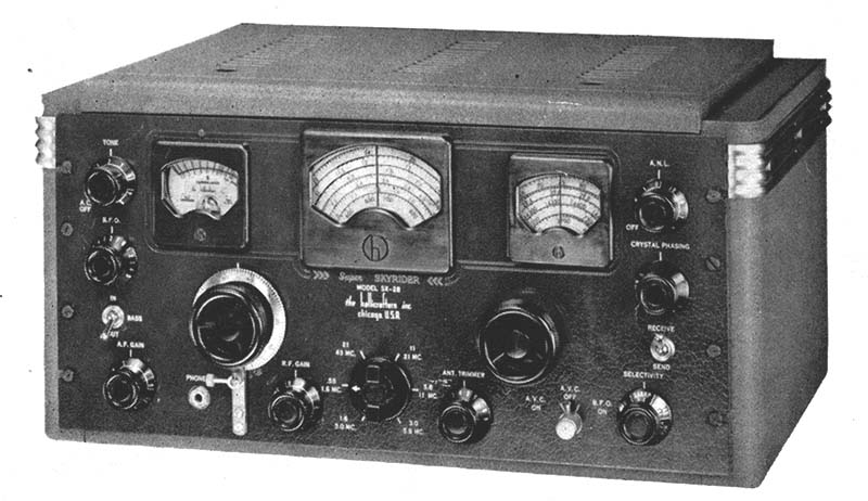
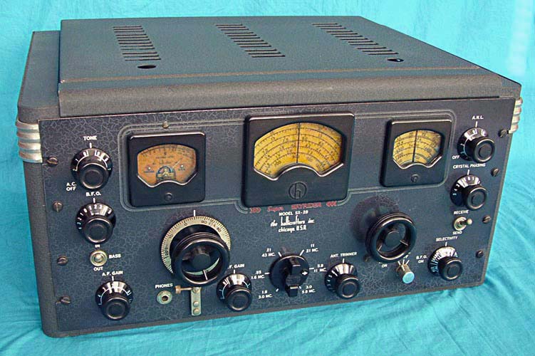
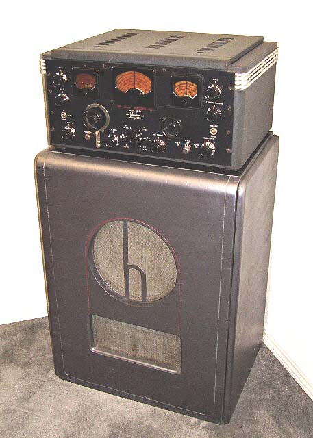
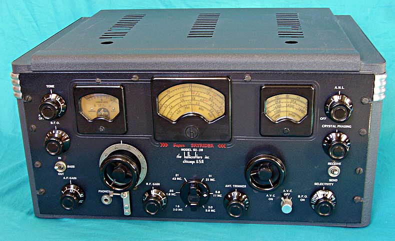
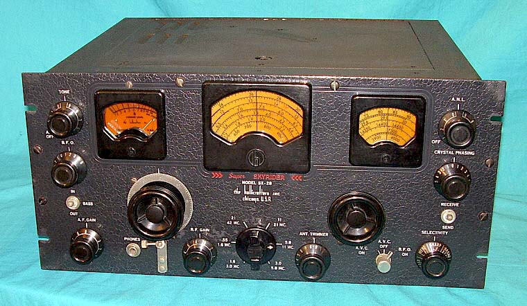
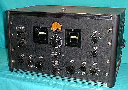
Radio Boulevard
Western Historic Radio Museum


the
hallicrafters inc.

 
SX-28

"a pre-war masterpiece"


(includes SX-28, SX-28A, AN/GRR-2 & R-45/ARR-7)

History, Various Models, Dating your SX-28 by Serial Number,
 Estimated Production Figures, Serial Number Log, Engineering & Production Changes,
Restoration Hints & Suggestions,
Performance Expectations, Competition Comparisons


by: Henry Rogers - WA7YBS-Radio Boulevard


YES, I know it's a SX-32. BUT,... it's just a great photo of KH6GQ, USN Lt. Wm. Griffin


the hallicrafters inc.
SX-28
(includes SX-28, SX-28A, AN/GRR-2 & R-45/ARR-7)
 

"a pre-war masterpiece"


The SX-28 is one of those receivers that just about every ham radio enthusiast has a passionate opinion about. No other vintage communications receiver, even those that were better performers, has such a dedicated following. Certainly, the SX-28's legendary performance that combines great audio with an impressive bench presence is responsible for the enthusiasm of its fans. This article provides a detailed history of the SX-28 manufacturing-production and how it evolved during WWII to become the SX-28A. Serial number analysis and a serial number log along with a chronological listing of Engineering Upgrades provides the tools necessary for accurately dating your receiver. Today, hundreds and hundreds of SX-28 and SX-28A receivers have been restored and are in use in Vintage Ham Shacks around the country (and around the world.) When rebuilt and aligned, the SX-28 is capable of providing great performance with incredible, bass-rich audio - probably why it remains one of the most popular of the "pre-war masterpieces."   H. Rogers - Nov. 2011
 

The SX-28 Receiver

The SX-28's 1940 Introduction


Hallicrafters announced the SX-28 "Super Skyrider" in July of 1940. The receiver's ultimate design was the result of the analysis of more than 600 requested reports, including input from government engineers. Twelve Hallicrafters' engineers were assigned the project of creating a receiver that not only satisfied government and commercial users but also gave the hams a receiver that performed better than any previous Hallicrafters. Additionally, the SX-28's modern, 1940 styling was to compliment the receiver's great performance.

The circuit utilized 15 tubes in a double preselection front-end on the top four bands and single preselection on the lower two bands. The frequency coverage was .55 to 43MC in six bands. Dual AVC systems with both delayed AVC and amplified AVC, Lamb Noise Silencer, Calibrated bandspread, Push-Pull Audio were some of the features incorporated into the design. The SX-28 would become an all-time ham favorite, famous for incredible audio coupled with amazing sensitivity, stability and selectivity - all at a reasonable selling price. Shown to the left are pages two, three and four of the multi-page advertisement in July 1940 QST that announced the SX-28. Page one of the ad states that the SX-28 was ",...mechanically and electrically designed by twelve engineers in our own laboratories." It further states that an exhaustive analysis of more than 600 requested reports, including input from government engineers were used for developing the performance specifications. Typical of a new product advertisement, conceptual artwork is used rather than actual photographs. Oddly, the ad states that the Super Skyrider is a 14 tube receiver but this is more than likely just an error from the advertising department.

sx28ad.jpg (24357 bytes)

Also shown on page two is the Jensen-Hallicrafters R-12 bass reflex speaker, an option that was available for $29.50. The text also mentions that a receiver with all of the features of the SX-28 could sell for as much as $250.00 but Hallicrafters' price of $159.50 was ",...figured on a slide-rule."
SX-28 User History - As Hallicrafters states in their initial advertising ",...input from government engineers,..." was used in the SX-28 design. So, it's not too surprising that some of the very first SX-28 receivers produced went to the FCC for use in their Radio Intelligence Division, the RID. The RID used the SX-28 receivers in several types of surveillance installations from mobile units to multi-operator monitoring stations. The mobile units were radio direction finding setups installed in automobiles that were used to find transmitters or transmitting stations that were being operated by enemy agents within the USA. The RID was quite effective in finding and stopping many enemy spy rings and other types of illegal transmitting. The FCC-RID SX-28 receivers were mostly in the first production run of receivers and were assigned serial numbers in the H-115,000 range.

The major source of SX-28 receivers for the ham market were the many ham radio dealers of the day. A lot of hams were located in small cities or in rural areas so they had to mail order their SX-28 receivers that ultimately were shipped to them by railway express. Of course, city hams could probably go to major radio dealers and buy their SX-28 direct. The ham market certainly dominated most of the sales in late-1940 and through 1941. At the beginning of WWII, all civilians had a short time period where they could still buy new products. It was April 1942 when most civilian production was converted to solely produce for the war-effort. After that, ordering a communications receiver like the SX-28 required approval of the War Department and that essentially shut down the civilian ham radio market for the duration.

From 1942 until late-1943, all Hallicrafters SX-28 production went to the military. The Navy had some special SX-28s built that were heavy-duty versions. These receivers had black wrinkle finish panels and metal data plates for identification. The Navy also had the RBY-1 receiver that combined the SX-28 receiver with a panoramic adaptor.  >>>

>>>  In early 1944, Hallicrafters introduced the SX-28A version. The "A" version reduced some of the essential materials, such as brass, used in the coil design and also redesigned the mechanical construction of the receiver's front end to make assembly easier and to reduce the costs and time of maintenance and repair. Some of the first SX-28A versions produced were heavy-duty Army-Navy versions designated AN/GRR-2 receivers. About 300 AN/GRR-2 receivers were built in early 1944. The standard version of the SX-28A also was produced concurrently with the AN/GRR-2 and then in fairly large quantities up to the end of WWII.

Post-WWII saw the civilian ham market open up almost immediately with most dealers offering the SX-28A as available by September 1945. The receivers produced from September to approximately October 1945 are identified as "SX-28" on the front panel. From sometime in October 1945 up to June 1946, the receiver has "SX-28A" on the front panel. About 4000 SX-28A receivers were produced with the "SX-28A" identification on the front panel.

Hallicrafters advertised in early 1946 that they had built 50,000 SX-28 and SX-28A receivers but this seems to be exaggerated advertising hype. Based on reported serial numbers, the estimated production is about 17,000 SX-28 receivers and about 11,000 SX-28A receivers for a total of 28,000 receivers. By adding in AN/GRR-2 receivers, RBY receivers, the heavy-duty Navy SX-28, R-45/ARR-7 receivers and other special builds it could be possible that about another 3,000 receivers, similar to the SX-28, were also produced which would bring the total up to about 32,000 receivers. It appears that all SX-28 and SX-28A receivers had a Hallicrafters data plate installed on the rear chassis with the serial number stamped into the tag. Only the aircraft receiver R-45/ARR-7 is serialized using a different format but its production probably only accounts for about 1500 receivers.

With the SX-28 introduction, the selling price was $159. The post-WWII price had escalated to $223. The SX-28 replacement receiver was the SX-42, introduced in August 1946. Although it was Hallicrafters' new "flagship" receiver, it didn't look anything like the old SX-28, and its standard HF circuit design additionally offered the buyer FM coverage from 27mc up to 108mc. The SX-42 never achieved the customer enthusiasm or the devoted following that the old SX-28 had. The SX-42 didn't survive very long as Hallicrafters' flagship either, with its production only going until mid-1947.


SX-28 Manufacturing History


Pre-WWII Versions


H-119051

1940 SX-28 SN: H-119051

The first few production runs of the SX-28 receivers have a several differences from the later production units. SX-28 SN H-119051 left the Hallicrafters' plant on October 29, 1940 - about two months after the SX-28 introduction and most likely from the second production run. It has most of the characteristics of the first SX-28 receivers, e.g., the front panel is painted blue-gray, no upper-center panel screws flanking the main dial bezel are used, it has the early style ANL circuit. By the time this receiver was built though, Hallicrafters had already changed the first RF amp tube from a 6SK7 to a 6AB7.

In 1950, the receiver's first owner, Paul Mauch, sold this SX-28 to W6EYC, Ray Umbraco of Richmond, California. 55 years later, I purchased this SX-28 from W6EYC's son. I totally rebuilt this SX-28 and the performance is very good but the original wiring of the Lamb Noise Silencer didn't use shielded wiring and there is a slightly increased hum level in some listening situations because of that. With the improved Lamb Noise Silencer, shielded wiring was used along with other improvements and this minor hum problem was eliminated (improved LNS installations began in December 1940.) H-119051 is an excellent  example of  the very early SX-28 production.


H-130170

The Hallicrafters-Jensen R-12 Bass Reflex Speaker

1941 SX-29 SN: H-130170 with matching R-12 floor speaker

When the SX-28 was introduced in the July 1940 issue of QST, it was shown with a large bass-reflex speaker. This was the Hallicrafters-Jensen R-12. There were actually three speakers available from Hallicrafters that were compatible with the SX-28. The PM-23 - a 10" table speaker - was standard. Also available was the Jensen-Hallicrafters R-8, an eight inch speaker in a small bass-reflex cabinet (probably for wall mounting.) The largest speaker-cabinet available was the R-12. The R-12 speaker-cabinet utilizes a wide-range 12" Jensen PM speaker with a 5000 ohm Z matching transformer to match the audio output of the SX-28. The R-12 cabinet is made up of five panels that clamp together using internally mounted clips. The back of the speaker screws in place and seals the cabinet except for the bass reflex port. The wood used is a soft lumber core that has a soft wood veneer. R-12s were painted a dark silver-gray, Hallicrafters called it "gunmetal," and the decorative incised arch was filled with red paint. Originally, the wire screen grilles were flocked with a champagne-colored mohair but this seldom survives today. R-12s were only available from late-1940 up to the beginning of WWII, which accounts for their rarity today.

SX-28 SN H-130170 with the Jensen/Hallicrafters R-12 Bass-Reflex Speaker shown in the photo left was originally sold in 1941 as a combination to W6ANX, Theron "Woody" Woods, whose QTH at the time was Los Angeles, California. This SX-28/R-12 combination was donated to the Western Historic Radio Museum in 2004 by Fred Jensen K6DGW on the condition that both units be restored. Fred had acquired the combination from Woody Woods' son after it had been discovered, stored in Woods' basement, in Auburn, California. I totally rebuilt the SX-28. Fortunately, it was "dead-stock" with no modifications and the receiver had only one serious problem. This was an unusual problem of very low gain caused by a broken powdered-iron slug in T-3 (last IF transformer - the slug is not adjustable but is glued in place for the correct L and then the transformer is tuned with compression trimmers.) I replaced T-3 with a good condition unit from a "parts set" SX-28. The R-12 was in pretty "rough" condition with peeling veneer and warped panels. All of the panels needed to be wetted and then clamped to straighten them. After the panels were straight and dry, I had to reglue the veneer and add some patches where the veneer was missing. I matched the paint by removing the "h" grille and using the "unfaded" paint that was protected by its mounting as the color sample. Performance of the SX-28 with the R-12 is fabulous. Vintage AM ham stations sound incredible and AMBC and SWBC are a pleasure to listen to with lots of bass available. Although several other pre-war communications receivers have audio output stages that can rival the SX-28, there is a certain appeal to listening to a receiver with such dramatic presence as the SX-28, especially when used with the R-12 speaker.

Want to build a replica R-12 speaker? I took this R-12 apart and photographed the interior in detail. I also measured all of the important dimensions and described the types of materials used in the original construction. Still interested? Phil Nelson of "Phil's Old Radios" has edited and hosts the article on his website.
Here's a link to the article:
  Build Your Own Hallicrafters R-12

SX-28 Chassis H-130170

The photo right is H-130170, a mid-1941 production SX-28, showing the typical chassis layout. Of note is the power transformer which has the standard Hallicrafters' "h" embossed on the cover. The glass tubes in front of the power transformer are the rectifier 5Z3 and the two 6V6 push-pull audio output tubes. The BFO section is to the right of the 6V6s. S-meter amplifier, first audio, detector and the last IF transformer for the sections across the front part of the chassis. On the left side is the second and first IF amplifiers, the Amplifier AVC sections and the Lamb Noise Silencer.

Under the condenser box cover are the front end tubes, RF1, RF2, Mixer and LO. This is the standard condenser box cover found on all SX-28 receivers up to late-1943.

The "spotty" chassis is typical of cadmium-plated steel when exposed to light moisture.


pm23.jpg (14332 bytes)

Hallicrafters  PM-23 Table Speaker

The Hallicrafters PM-23 was the standard speaker for the SX-28 and SX-28A along with the SX-24 and SX-25. The PM-23 was first introduced in 1939 for use with the SX-23 and was still available through 1946. The 10" Jensen speaker has a 5000 ohm to 8 ohm transformer to match the speaker to the typical Hallicrafters' audio output impedance. The chrome "h" was installed on all PM-23 speaker grilles until about 1943 when it was discontinued for the duration of WWII. At about the same time, the magnet cover was eliminated from the speaker frame. The post-WWII Hallicrafters ads do show the return of the chrome "h" but whether this applies to all post-WWII PM-23s is unknown. Most speakers are dated in some manner - ink-stamped on the frame or cone is most common. This PM-23 is dated "5-40" and was originally sold with SX-28 SN H-119051.

photo left: PM-23 speaker

photo right: Leo Meyerson W9GFQ (World Radio Labs) with an early SX-28 & PM-23  -  QST April 1941


WWII Versions

1942 SX-28 SN: H-151197

SX-28  SN H-151197 left the Hallicrafters plant on February 21, 1942 and was purchased by W3ON, John Ridgway, who kept the receiver in superb original condition for his 55 years of ownership. I purchased the receiver from John, who was 85 at the time (1997) and living in Galena, Nevada. John stated that the SX-28 was ",....so damn heavy I can't even turn it on its side anymore!"  Note that the front panel on this receiver is very dark gray-blue-black and there are panel screws flanking the main dial bezel. Internally, the receiver has the redesigned Lamb ANL circuit and the bandspread dial is driven by a dial string. The W3ON SX-28 is certainly an excellent reference as to how the later SX-28 receivers looked when new.

Although H-151197 left the Hallicrafters' plant in February 1942, it was actually a "civilian" purchase. It was April 1942 before almost all of the US manufacturing completely changed over to "War Production." John purchased this receiver just before the civilian market ended in April 1942.

Having seen hundreds of SX-28s over the years, I am fairly sure that H-151197 is probably one of the best condition, original receivers to have survived. It is all original parts with the exception of the S-meter load resistor. It has its original warranty card, the original inspection tag, the original bottom cardboard cover and the original manual. John kept his receiver in a "dark" room (usually the curtains were drawn during the day and only a small desk lamp provided light.) This lack of bright light and John's meticulous care has preserved H-151197 in an exceptional original state.

H-151197


AN/GRR-2  -  WWII Army-Navy "Heavy-Duty" SX-28A


During the later part of the SX-28 wartime production, some versions were built with heavy-duty parts and other changes that were certainly at the request of the Navy and the Signal Corps. These heavy-duty SX-28 receivers have a General Transformer Company power transformer that is potted, Korite dipped filter choke and audio output transformer and also feature the return to the gear-driven bandspread tuning. The Navy versions sometimes have different front panels that are black wrinkle finish with a military tag in place of the "the hallicrafters inc." identification. These heavy-duty SX-28 receivers are typically rack mount configuration. Serial number H-169129, owned by W7KXB, is an SX-28 receiver with many of these heavy-duty characteristics.

When the SX-28A was introduced in early 1944 some of the first production SX-28A receivers were produced in the heavy-duty configuration. These "special" receivers were designated as AN/GRR-2 and were specifically built for military use. Though almost all of the SX-28A receivers built from 1944-45 were in the standard configuration with table top cabinet, it appears that only one production run was made for the AN/GRR-2 receivers since all known examples were built within the April-May, 1944 time period.

The AN/GRR-2 receivers were quite different than the standard SX-28A (and the earlier heavy-duty SX-28 models) and featured rugged construction with fungus proofing, rotary switches that were wax impregnated and the IF transformers that were vacuum and wax impregnated.  


HA-2703

Like the earlier "heavy-duty" SX-28s, the AN/GRR-2 power transformer was the same potted unit made by General Transformer Company and the filter choke and audio output transformer were dipped in Korite (a black tar-like moisture proofing.)Also included was the heavy-duty gear-driven bandspread dial (that had been used in the early pre-war SX-28s.) The chassis wiring uses military type stranded wire with white cloth insulation. All AN/GRR-2 receivers are MFP treated and are exclusively in the rack mount configuration but its dust cover design allows the receiver to be used as a table top unit also.

AN/GRR-2 SN: HA-2703 fortunately has the fungus proofing stamped date still legible, May 27, 1944. Even though it was a special-build receiver, the AN/GRR-2 still has the standard Hallicrafters' ID plate with serial number riveted to the rear of the chassis. HA-2703 has its original heavy-duty dust cover installed as seen in the photograph above.

The AN/GRR-2 had its own US Army Signal Corps manual, the TM-11-874 which is much more detailed than the standard Hallicrafters' SX-28A manual (see Manual Errors below.) The AN/GRR-2 receivers have a front panel is copper plated under the paint for corrosion protection, the ball-end toggle switches have sealed bakelite cases and the S-meter has a bakelite case with scale mounted needle stops and a yoke type mounting system (which accounts for the panel screw adjacent to the main tuning logging scale (at about 10 o'clock.)

AN/GRR-2 Chassis - The AN/GRR-2 chassis is very similar to the standard SX-28A in appearance. The exception being the AN/GRR-2 power transformer, as seen in the photo below-left. Standard for the SX-28A and the AN/GRR-2 is the "clip-on" condenser box cover with louvers. All tube types and locations along with the other above chassis components are similar in appearance to the SX-28.

AN/GRR-2 MFP Date Stamps and Production Numbers - I have received a couple of reports regarding AN/GRR-2 receivers and their MFP date stamps. A report was received from IØGEM - owner of AN/GRR-2 sn HA-2766. Maurizio reports that the MFP date stamp is May 27, 1944. This AN/GRR-2 is 63 serial numbers after my AN/GRR-2 sn HA-2703, which is also MFP date stamped May 27, 1944. It's unlikely that all 63 serial numbers were assigned to AN/GRR-2 receivers, so this date stamp doesn't really reveal any information regarding AN-GRR-2 production quantity. Another interesting report came from Chuck K3XU, who sent me his AN/GRR-2 serial number, HA-2506, which is 260 serial numbers before HA-2766 and it is MFP dated May 9, 1944, sixteen days before both HA-2703 and HA-2766 were MFP date stamped. HA-2686, a standard SX-28A, was produced during this time which shows that AN/GRR-2 receivers were not the only type manufactured during this period. It is also interesting that only 260 serial numbers were issued in a 16 day period indicating that production that used the "HA" prefix was fairly low at this time. Since the serial numbers of these three AN/GRR-2 receivers seem to track the MFP date stamps, it is reasonable to assume that it is likely that the MFP treatment was applied at Hallicrafters. Carl WA1KPD has reported his AN/GRR-2 SN: HA-2278 with MFP date-stamp of April 26, 1944. The earliest AN/GRR-2 reported, so far, belongs to N9WHH, sn: HA-2200. The span of serial numbers from HA-2200 to HA-2766 is 566 numbers. As mentioned, there are standard SX-28A serial numbers within that 566 numbers so the estimate of about 200 AN/GRR-2 receivers built is certainly possible.

TM11-874 (Manual) Errors - The AN/GRR-2 manual TM11-874 has more than its share of errors, especially in the schematic where several errors are obvious. For example the power transformer primary isn't fully drawn. R17, the 1st IF screen load resistor is entirely missing. Some of the voltages shown in the troubleshooting section are wrong (off by 100 volts.) When working on the AN/GRR-2 and using TM11-874, be sure to also have the standard Hallicrafters SX-28A manual as a cross-reference to check any questionable circuit connections or other confusing information.


MODEL RBY - NAVY DEPARTMENT

SX-28 Receiver with Panoramic Adaptor


The RBY was a Navy piece of equipment that used a SX-28 combined with a Panoramic Adaptor with 3" CRT. The Panoramic Adaptor that was supplied by Panoramic Radio Corp. who built almost all of the panadaptors at the time. The SX-28 was almost the stock version with only a few minor changes. The SX-28 has an SO-239 installed on the back apron of the chassis to connect the Panoramic Adaptor. The output from the SX-28 used a high value resistor to couple the Mixer plate to the SO-239 connector and then via coaxial cable up to the panadaptor input. The version I saw also had a buffer circuit assembly on the antenna input apparently to allow multiple receivers to use a single antenna. The SX-28 receiver has a military tag where the "SX-28" ID is on the front panel and it identifies the receiver as CHL-46195. The panel is black wrinkle paint - not the standard gloss black heavy-textured panel. The RBY-1 receiver that was examined did have the standard Hallicrafters serial number tag installed on the rear of the chassis with the number H-181853, indicating late 1943 production. The RBY was an earlier version but probably still dating from about 1943. 

The introduction of the AN/GRR-2 in February 1944 became the Navy SX-28A. The "AN" designates "Army-Navy" so the AN/GRR-2 was used by both U.S.Army Signal Corps and U.S.Navy. Post-WWII, Hallicrafters offered the S-35 and this version used the SX-28A receiver and a 5" CRT on the panadaptor.


R-45/ARR-7 - WWII Airborne Search and Surveillance Receiver
The R-45/ARR-7 is really nothing like the SX-28A but it's included here to debunk the commonly-heard "Airborne SX-28A" myth
 

 The R-45/ARR-7 was an airborne search and surveillance MF and HF (.55 to 43mc) receiver that was primarily used for visual analysis of enemy radar and other types of signals. Some of the R-45 circuitry, a few of the components and a little of the basic design share a few similarities with the SX-28A. However, the receiver was for airborne installations, so the entire package was lightened considerably and the circuit reduced to the needed essentials. The R-45/ARR-7 was designed solely for search and surveillance. It wasn't a communication receiver and it certainly wasn't a "pleasure band-cruiser." Surveillance required the ability to scan frequencies in search of enemy signals so a motor drive tuning was provided for automatic scanning of frequency ranges that were operator-set with reverse direction switching provided at each end-limit of the tuning scan. To aid the analysis of enemy signals, the receiver also provided Panadaptor and Video Outputs that were designed to feed into specific airborne versions of typical panoramic adapters and oscilloscopes. The APA-10 had a built-in oscillator to create lissajous patterns for audio analysis of incoming signals (Video output is from the 6V6 audio stage of the receiver.) The lissajous patterns (based on the test oscillator input) allowed the operator to measure radar pulse rates and thus identify the particular type and origin of the signal. The APA-10 also included a panoramic adaptor function that monitored the output of the Mixer stage of the receiver and provided a visual representation of the spectrum surrounding the receiver's RF passband. This allowed the operator to "see" signals that were outside the receiver's IF passband that couldn't be heard. But they could be seen on the panadaptor thereby alerting the operator to tune to the signal for further investigation.

The R-45's circuit is only vaguely similar to the SX-28A and the receiver itself is "stripped down" to the essentials and considerably lightened for aircraft use. The R-45 uses 12 tubes (not counting the rectifier located in the PP-32 power pack) and has six tuning ranges. Some of the similarities to the SX-28A include using the same Micro-set coils in the front end, using double preselection above 3mc, it provides six selectivity steps, three of which utilized the crystal filter and its IF transformers are similar to the SX-28A. Some of the important circuit differences from the SX-28A include the use of a VT-150 voltage regulator tube (the SX-28A didn't use any VT voltage regulation,) using a 6SK7 1st RF amplifier tube (the SX-28A used a 6AB7,) using a 6AB7 "re-radiation" tube (a unity-gain buffer between the ANT. input and the RF amplifier circuit to prevent LO leakage to the antenna,) using a "clipper-type" Noise Limiter circuit (instead of the fabulous Lamb Noise Silencer,) no bandspread is provided, no antenna trimmer is provided, no amplified AVC is provided, the S-meter circuit is completely different and the "militarily" basic audio output system is just a capacitive coupling from the 6V6 plate to drive the headphones. The audio output of the R-45 was really only intended for headphones but a 600Z ohm loudspeaker will provide ample volume even though the audio quality is considerably different if compared to the SX-28A's 8 watts of Push-Pull audio output power. However, the R-45's audio wasn't for "listening pleasure" and the receiver was never intended as a "shortwave listener, ham receiver, band cruiser." It was a intended for the surveillance radio operator to use the aural information along with the visual indications for complete analysis of enemy signals.

Today, most R-45/ARR-7 receivers that are encountered will have had "hamster" modifications incorporated into the circuitry and usually the motor drive assembly is removed. The purpose for and performance of the re-radiation circuit became the focus of most modifications with the belief that this unity-gain buffer was adversely affecting receiver sensitivity. Certainly, the lethargic carrier level meter action gave users the impression that the receiver had no sensitivity. However, the carrier level meter was purposely damped to keep it from being "pegged" when various test oscillators were in use analyzing signals. The surveillance operators rarely used the carrier level meter because more critical information was available from the panadaptor. Undoubtedly, the mistaken belief that the R-45/ARR-7 was a "SX-28A in an airborne configuration" was responsible for most of the modifications which were incorporated in an attempt to "rebuild" the R-45 into a SX-28A - something it was never intended to be. The R-45/ARR-7 will perform quite well with ample sensitivity in its original configuration but only after it has been thoroughly checked out, repaired as necessary, any weak or defective tubes replaced and, most importantly, a complete IF/RF alignment performed. A resonant antenna must be used for best performance. And,...most importantly,...ignore the carrier level meter,...the surveillance operators did.      >>>


SN: 732

>>>    When airborne, the R-45 was powered by the PP-32 power pack that provided the heater voltage (6.3vac) and the B+ (+275vdc) but the scanning motor drive was powered by the aircraft battery system (+24vdc at 350mA when operating.) Additionally, the PP-32 operated off of 115vac 400 cycle provided by the aircraft's ac system. The PP-32 actually was able to power three receivers and the R-45 was usually paired with the VHF R-44/ARR-5 which was the airborne version that had some similarities to the S-36. Like most WWII equipment, not all R-45 receivers were built by Hallicrafters. Other contractors included Belmont Radio Corporation. The R-45 shown in the photo above is from 1944 and was built by Hallicrafters and has the serial number of 732. The R-45 receivers do not use the standard Hallicrafters serial number metal tag and do not use the HA serial numbers.

For more detailed information on the R-45/ARR-7 go to "WWII Airborne Radio and Air Nav Equipment" which is part 2 of the WWII Radio Equipment section. Use Home/Index to navigate.


Post-WWII Versions

sx28a.jpg (27923 bytes)
HA-25583

1945 SX-28A, SN HA-25583

This early example of the civilian SX-28A (probable build date November 1945) doesn't have the "SX-28A" designation on the front panel even though earlier serial numbers have been reported with the "A" panels. Civilian production started in September 1945 and continued until around July 1946 when the new 1947 models were introduced. The front panel identification was changed to "SX-28A" in November 1945, so HA-25583 must have been one of the receivers built with an "old stock" panel from intermixed stock. This photograph shows the "heavy texture" front panel that really enhances the SX-28A's appearance.


 (I  purchased this receiver at a California Historical Radio Society swap meet in the 1980s. I restored the receiver and repainted the cabinet with Illinois Bronze "French Gray" Wrinkle Finish paint - too bad it's no longer available. I used this SX-28A  for several years but reluctantly sold it in 2004)


Production History, Identifying Indicators and Serial Number Analysis

Dating an SX-28 Receiver by Serial Number

Why is it so difficult to find production information on the Hallicrafters' receivers? After all, they were one of the "big three" (Hallicrafters, National and Hammarlund) from the late thirties up into the 1960s. Unlike National, a company that just recently went out of business (1991) or Collins, a company still in business (though owned by Rockwell,) Hallicrafters was unfortunate enough to have been purchased by Wilcox Instruments, a division of Northrop, in the early 1970s. Wilcox was also known as Wilcox Electric and was located in Kansas City. One of the first orders of business at Wilcox was to DESTROY ALL of the Hallicrafters records and archives. I wrote a letter to Hallicrafters in 1975 that was forwarded to Wilcox Instruments. They did reply to my letter but made it very clear that no records or archives existed anymore. I have also had visitors in our museum that worked at Wilcox Instruments in the 1970s and were present when the orders were issued to destroy the Hallicrafters' archives. There were protests from the employees ordered to carry out the destruction but it was to no avail. Some records were "smuggled" out of the plant but it was only a fraction of what was destroyed. Most of these surviving records are probably in private collections. Since there are no company records available for reference to production dates or quantities, we have to use other methods to reconstruct what most likely took place during the SX-28 production period.

HALLICRAFTERS' SERIAL NUMBERING METHODS UP TO WWII: Hallicrafters' serial numbers on early equipment consists of a number sequence in addition to a manufacturer code number. This was because prior to late 1936, Hallicrafters' receivers were built by contractors, such as Howard Radio Company or other contractor companies. When Hallicrafters was able to build their own equipment (late 1936) they began assigning a serial number consisting of an "H" prefix followed by five numbers. The serial numbers were assigned sequentially to all products as they left production and not exclusively to any model line. There are exceptions to the "H" followed by a five digit number format. Accessories and smaller items that were serialized sometimes have an "H" followed by a four digit number.

Estimating a dynamic, like production, is difficult and we are going by assigned serial numbers compared to inspection tag dates and date codes on components. Inspection tags tie a serial number directly to a known manufacturing date. Date codes can be used as a double check to assure a production estimate "makes sense." Additionally, many radio manufacturing companies reduced or stopped their production during the early summer months, at least prior to WWII, so we are not counting May or June as "full" production months until 1942. Most companies used this time for design and tooling changes along with new product introduction.

By mid-1938, Hallicrafters' serial numbers were up to H-80,000. A dated inspection tag shows SN H-83879 was assigned on November 11, 1938. Another dated inspection tag shows that serial number H-85531 was assigned on December 19, 1938. These two tags are separated by approximately one month and show that 1652 serial numbers were assigned during that time period.  >>>

>>>  By late-1939, the numbers were in the H-100,000 range. By estimating that Hallicrafters assigned between 1600 and 2000 serial numbers per month at this time, the SX-28 production should start (approximately) with serial number H-115,000. VE3CSQ owns SX-28 H-116368 which happens to still have its original inspection tag that is dated September 27, 1940. This is the earliest SX-28 inspection tag that has turned up (so far.) SX-28 SN H-119051 was assigned on October 29, 1940, about one month later and shows that 2683 serial numbers were assigned (mostly in the month of October.) This shows that Hallicrafters was increasing their output, perhaps preparing for the 1940 Christmas sales season and also probably due to increased demand as the company grew. It appears that from August 1940 up to about May 1941, production was approximately 2000 to 2500 average assigned serial numbers per month. Variations in output occurred since there was always a rush in the late fall towards Christmas and then a subsequent slowdown in the winter to spring season. Another original inspection tag has turned up on a pre-war SX-28 owned by Robert MacIntyre - H-127986 with a tag dated March 19, 1941. During the fall of 1941, Hallicrafters must have again increased their manufacturing capacity because, starting in October 1941, production seems to be at a rate of about 2,500 to 3,000 assigned serial numbers per month. By February 1942, the serial numbers were up to H-150,000. SX-28 SN H-151197 was assigned on February 21, 1942. Comparing SX-28 H-127986 3/19/41 to SX-28 H-151197 2/21/42 gives a total of 23,211 serial numbers assigned in that 11 month period. Remember, these numbers are for all Hallicrafters' products and while they can determine a probable date of manufacture for a particular receiver, it requires other data to determine what percentage of production the SX-28, or any other product, represented.

NOTE on Serial Numbers and Production Runs: It is interesting that the very early SX-28s seem to be in two production runs as referenced to the serial numbers reported so far (May 2009.) We have many serial numbers reported in the H-115xxx to the high H-116xxx range but we have only three serial numbers from the H-118xxx and 119xxx range (with one other H-119xxx unit known to have sold on eBay.) No serial numbers have been reported assigned to SX-28s from the H-117xxx range. Also, the H-115xxx and H116xxx receivers have the 6SK7 RF amp while the H-119xxx receivers have the 6AB7 RF amp - a specific change to the production receiver. This could imply that SX-28s (at least the early pre-war ones) were built in production runs of some fixed quantity rather than just a constant built rate. The production run method is certainly how most companies did handle their build schedules, especially when their production was not to specific orders and the company produced more than one type of product. As more serial numbers are collected the picture of how Hallicrafters handled their production schedules might become clearer. Keep reporting your SX-28 and SX-28A serial numbers and thanks to all who have reported their numbers so far, it has provided valuable information. An e-mail link for reporting your SX-28/28A serial number is provided below in the "Assigned Serial Numbers - Serial Number Log" section.


WWII SX-28 Production Serial Numbers, Military Versions
 and the Introduction of the SX-28A - 1942 to 1944

During WWII, Hallicrafters' output again increased significantly, however the nature of the production changed from amateur receivers and transmitters to equipment required by the military. After about April 1942, it was impossible for civilian amateurs to buy receivers like the SX-28, as everything produced at Hallicrafters was destined for military or government use. Consequently, SX-28 and other "amateur" receivers accounted for less and less of the total production output. Use of the "H" prefix serial numbers slows down during WWII. Towards the end of 1943, the serial numbers were up to H-180,000. Hallicrafters decided to end the "H" prefix and start a new "HA" prefix with numbers beginning at 1000. It appears that the change over to the "HA" prefix happened around December 1943 or possibly January 1944. As a result, SX-28 serial numbers beginning with the "H" prefix end around H-183,000 but some very late production SX-28s will have serial numbers with the "HA" prefix. In fact, three SX-28s have turned up that have the "HA" prefix serial number (HA-2126 is one of them.) HA-2126 does have the old style SX-28 coils installed in the old style RF box, indicating that it is indeed an SX-28 and not an SX-28A (the other two "HA" receiver photographs did not show the underside of the chassis and the RF coils so they could not be positively identified as SX-28s though all of the other SX-28 indicators were present.) This receiver shows that SX-28 production continued into the first part of 1944 with the introduction of the SX-28A probably occurring around March or April of 1944. The earliest SX-28A reported is actually an AN/GRR-2 version with a serial number of HA-2278 with a MFP stamp of April 26, 1944. This AN/GRR-2 serial number is most likely from March or early-April 1944. Certainly, Hallicrafters was in the process of designing the "SX-28A" upgrades at the time of the change over to "HA" serial numbers but the indications are that the "HA" prefix was certainly not specifically for the SX-28A model. It is possible that Hallicrafters intended for the SX-28A production to coincide with the beginning of the "HA" serial numbering sequence but the new coils and harnesses required new assembly procedures/models and new test/alignment methods which may have delayed the SX-28A introduction for a short time. Use of the "HA" prefix serial numbers for 1944 and 1945 progressed very slowly as the demand for other types of military equipment was by far of greater quantity than for surveillance receivers, like the SX-28A, SX-36A and the few other users of the "HA" prefix serial numbers.

SX-28 SN: H-180455 - This receiver is very late in the SX-28 production, dating from around September 1943. It is obvious that this receiver has the heavy-textured front panel and the main tuning and bandspread knobs are the later "webbed" type. This receiver also has the louvered cover over the tuning condenser that is screwed to the top of the condenser-RF box. This receiver illustrates that the late production SX-28 receivers were fitted with parts that formerly were thought to be exclusive to SX-28A production. H-180455 is owned by Oliver Gerondeanos who also supplied the photograph.
 

SX-28A Post-War Production and Serial Number Dates for SX-28A on Front Panel

When WWII ended in August, 1945, Hallicrafters almost immediately started civilian production of several pieces of equipment that had formerly been for the military. The civilian SX-28A production started in September 1945 and most dealers at that time were offering to take "advance orders" for when they actually got the SX-28As in stock. Though the use of serial numbers for the SX-28A had been rather conservative during the war, the production use of the HA serial numbers for civilian amateur equipment market from September 1945-on was fairly rapid. It is likely that all SX-28As with serial numbers higher than about HA-20,000 are probably post-war production - remember, other receivers were also using the HA prefix serial numbers, so even though probably only about 1000 to 2000 SX-28As were produced during 2/44 thru 8/45, other equipment accounted for the remainder of the serial numbers assigned. SX-28A SN: HA-18933 was reported and that receiver has a date stamp on it of May 21, 1945 which indicates a late-WWII build for that receiver.

The appearance of  "SX-28A" on the front panel occurred rather quickly after civilian production began in September,1945. Paul Rosen CET owns the earliest seen SX-28A with "A" on the front panel, with a serial number HA-25171. This puts the addition of "A" in the front panel nomenclature to around September, 1945. However, I owned a later serial number, HA-25583 and it didn't have "A" on the front panel. Also, KF4TP owns two SX-28A receivers, one is HA-27742 without the "A" on the front panel. His second receiver is HA-27748 does have the "A" on the front panel. Only six serial numbers separate these two receivers and date the assignment to around September, 1945. The separation of HA-25171 with the "A" and HA-27742 without the "A" is 2571 serial numbers. HA-31195, an "A" front panel receiver, has its original inspection tag dated October 8, 1945. This is about 5000 serial numbers after the earliest "A" reported and indicates that "A" front panels were available either at the end of WWII or just after.

Since these serial number assignments all occurred during the "Christmas Season rush," production would have been at its highest volume for the year, probably at least 1000 units per week (especially of the lower cost receivers that made good Christmas presents.) This would make the actual time interval between the assignments of HA-25171 and HA-27742 about two weeks. It is very likely that intermixed stock accounted for this interesting anomaly and in a "production environment" this would be considered a common occurrence.

Approximately 4000 SX-28A receivers were produced with the "A" designation on the front panel. If this estimate is based on earliest serial number encountered with "SX-28A" on panel (HA-25171) to latest SX-28A serial number encountered (HA-53445) this results in 28,274 serial numbers issued with 15% assigned to SX-28A receivers equals 4241 receivers with "SX-28A" on front panel. However, since the earliest "A" appearance happens before the Christmas Rush and there are several examples of "non-A" panels that post date HA-25171, we are going to assume that intermixed stock accounted for a lower percentage of "A" panels used in production for a short time (two weeks or so.) Since this is an approximation and is taking into account intermixed stock, the number of 4241 receivers is rounded off to about 4000 units. Also, since this estimate is just for the post-WWII production, 15% is used for SX-28A percentage of assigned serial numbers since there were several other models also using the "HA" serial numbers. It appears that in June 1946 there was a run of the last SX-28A receivers. These last '28As are in serial number block HA-153xxx. Seven have been reported with the numbers spanning HA-53170 up to HA-53445. These receivers were probably all built in June 1946. By July 1946, the new 1947 models were introduced with the SX-42 taking the "flagship" position that the SX-28 had occupied for the past six years. The SX-28  had provided pre-war hams with a great receiver at a bargain price, while during WWII the SX-28 filled many different occupations from intercept to entertainment.  The SX-28A eased front end manufacture and alignment while conserving necessary materials and, after the war, hams still had an opportunity to purchase a brand new version of a receiver they may have become familiar with while serving in the military. Revered, admired and respected,...the SX-28 and the later SX-28A were and still are among the great pre-WWII receiver creations.

angrr2.jpg (30109 bytes)

1945 Military-Commercial SX-28A Rack Mount Receiver, SN HA-11774

The military and some government users purchased the SX-28A in the rack mount configuration, with characteristic rack mount top dust cover and (though it can't be seen) bottom cover. Some are fungicide treated which sometimes leaves a red colored coating on solder joints and around tube sockets. The circuit is identical to the standard cabinet SX-28A though some of the rack mounted SX-28As had plexiglass windows in the dial covers. These receivers are different than the US Army Signal Corps AN/GRR-2 receiver in that they will have the standard audio output transformer and choke along with the Hallicrafters' power transformer. Additionally, these receivers have the dial string drive on the bandspread dial. Also, long handle toggle switches are used along with the metal cased S-meter. 

This receiver is owned by: KØDWC, Charles Cusick, Dayton, Nevada


  Identifying SX-28As that have "SX-28" on the Front Panel

From its introduction in early 1944 until the front panel receiver identification change in September 1945, all SX-28A receivers are identified as "SX-28" - at least according to the front panel. As far as Hallicrafters was concerned, the designation "SX-28A" applied only to receivers that had the Hi-Q, Micro Set coils in the front-end. Nowadays, all Hallicrafters enthusiasts agree with this definition. However, there are several characteristics that can be used to identify an SX-28A without turning the receiver on it side to look at the coils thru the slots in the bottom cover. These are known as the SX-28A "indicator parts." They are not entirely reliable for ID but, generally, it's a quick way to tell from a distance what the receiver is. ALL SX-28A receivers will have webbed tuning and bandspread knobs, a heavily textured front panel, a clip-on louvered condenser box cover and a serial number prefix "HA." While all SX-28As have these parts, unfortunately we can't say that none of the SX-28s would have had these parts installed. It is known that some of the very late SX-28s were fitted with webbed knobs. Certainly, some of the late SX-28s have a louvered condenser box cover though it was mounted with screws (not clip-on.) It is known that the heavy-textured front panel also made its appearance prior to the introduction of the SX-28A. >>>

>>>  The changeover to these later parts seems to be on SX-28 serial numbers higher than H-180,000, or in late 1943. The change to "HA" prefixes began around January 1944 (possibly as early as December 1943) and seems to only predate the introduction of the SX-28A by a couple of months. This series of events would account for some late SN SX-28s that have webbed knobs (H-181958, HA-2126), louvered condenser cover (H-173611, H-174842, HA-2126) and heavy textured front panel (H-178848, H-181715, HA-2126.) Since these parts were incorporated into late SX-28 production, we can't be 100% sure just by looking at these parts if a receiver is an "A" or non "A."  Even the appearance of the "HA" prefix in the serial number is not a sure indicator. Three SX-28s have turned up with the "HA" prefix serial numbers (HA-2126 is one, the other two have not been confirmed.) These receivers have all of the SX-28A indicator parts (louvered condenser cover is screw mounted though) but the coils are the old SX-28 style and the RF box is the old SX-28 style. Though it is likely to change as more SX-28s are photographed, it does appear that for now the SX-28A exclusively uses the clip-on condenser box cover and does not have the auxiliary relay socket and will, of course, have the Hi-Q Micro Set coils. ONLY the Hi-Q Micro Set coils are the 100% sure indicator since they were the reason for the designation change. Fortunately, if it's really important to know in advance of purchase whether the receiver in question is an "A" or non-"A",  you can turn the receiver on its side and, if you've seen what the Hi-Q Micro Set coils look like, they are visible thru the openings of the bottom cover
 

Component Date Codes for Build Date Confirmation
(only works on pre-WWII SX-28)

There are three date-coded parts used in the pre-war SX-28 that provide specific information as to when the part was made. From that, one can certainly assume that the receiver was built later than that date. The audio output transformer is usually stamped (on top) with a numeral month and year, e.g., "2 Stc 41", or February, 1941 (the "STC" separating the month and year is the logo for Stancor.) The filter choke is also sometimes stamped in the same format, however use of a date code on this part seems to have been sporadic. These parts are only a source for early SX-28 models as, by early 1942, Stancor had eliminated the date code information. The bass choke is another part stamped with a date code. SX-28 SN H-119051, built 10-29-40, has a date-coded bass choke "10 Stc 40" showing that it is possible for newly arrived parts to be immediately used by production. The date coded bass choke disappeared about the same time as the dated coded filter choke. Photo right of the top of the bass choke showing the date code information. The logo is for Standard Transformer Corporation (Stancor.) 55-010 is the part number. 10 is the month and 40 is the year of manufacture. This bass choke is from SX-28 SN H-119051 (10-29-40.)

datecode.jpg (5751 bytes)

On some SX-28A and AN/GRR-2 models a date was ink-stamped on the back of the condenser box when (and if) the receiver was fungicide treated. A stenciled form was applied to the condenser box with all of the treatment information including the year. The actual date was rubber stamped in a space provided. Usually, the format is a small "month-day" - MAR 7, for example that was rubber stamped and then a larger, two numeral year, e.g. "45" for 1945, which was part of the stencil. The date coded MFP stencil provides an indication of when the receiver was built since it seems likely that Hallicrafters applied the MFP and stamped the receivers at that time. Normal production processes would have the MFP applied after final test and alignment (so the technicians knew there shouldn't be anymore soldering required) and before final inspection. The MFP date should be within a day or so of the final date on the inspection tag that would have been included with the receiver when it shipped. Photo right is of the fungicide treatment stencil which is usually located on the back of the condenser box. The date of "45" is part of the stencil. The smeared rubber stamped date is "MAR 7." This stencil is on Military Rack Mount SX-28A SN HA-11774.

fungitag.jpg (7245 bytes)


Assigned Serial Numbers - August 1940 to June 1946

The following chart is based on observed serial numbers compared to dated inspection cards and date coded parts or date coded stamps on SX-28, SX-28A and AN/GRR-2 receivers. It is an approximation that takes into account the slow increase in production in last part of 1940, the dramatic increase in production through 1941 and into the first third of 1942, the drop in production during WWII (especially 1/44 thru 8/45) with the subsequent increase of civilian SX-28A production starting in September 1945 and running through the first part of 1946. Dated inspection card confirms H-116368 was assigned September 27, 1940 and another dated inspection card confirms HA-53513 (on S-40 receiver) was assigned on June 18, 1946.

Earliest SX-28 serial number encountered:  H-115251 (owned by K7MCG)

Latest SX-28 "H" prefix serial number encountered: H-181958 (seen on eBay)

Latest SX-28 serial number encountered: HA-2126 (seen on eBay)

Earliest SX-28A serial number encountered: HA-2200 [AN/GRR-2] - (owned by N9WHH)

Earliest SX-28A serial number with "SX-28A" on front panel: HA-25171 (owned by P. Rosen)

Latest SX-28A serial number without "A" on front panel: HA-27888 (owned by M. Kaplan)

Latest SX-28A serial number encountered: HA-53445 (owned by WØFB)


     MONTH/YR.                    SERIAL NO. RANGE

Aug 1940  to  Dec 1940 . . . . . . . . . . H-115,000    to    H-124,000

Jan 1941  to  Dec 1941  . . . . . . . . . .   H-124,000   to   H-145,500

Jan 1942  to  Dec 1942 . . . . . . . . . . . H-145,500    to   H-166,500

Jan 1943  to  Dec 1943 . . . . . H-166,500  to  H-183,000/HA-1000

Jan 1944  to  Dec 1944 . . . . . . . . . . . . HA-1000    to    HA-8,500

Jan 1945  to  Dec 1945 . . . . . . . . . . .  HA-8,500   to   HA 35,500

August 1945, end of WWII . . . . . . . . . . . . . . . . . . . . ~ HA-22,000

Jan 1946  to  June 1946 . . . . . . . . . . . HA-35,500   to   HA-55,500


 Serial Number Log

SX-28, SX-28A and AN/GRR-2 Receivers


In keeping with the tradition started with our DD-1 article of providing a log of known serial numbers for receivers, we are now providing the same resource for SX-28, SX-28A, AN/GRR-2 and R-45/ARR-7 receivers. The serial numbers are sorted by date of manufacture (more-or-less chronologically) and by model type. Having an online source to reference your serial number will provide you with data as to approximate date of manufacture and general identification. If you have sent me your SX-28 serial number in the past and it is not in the log, please send it to me again and I'll make sure it is listed. When sending your serial numbers be sure to let me know the specific type of SX-28 or 28A receiver you have. Send your serial numbers to:

 WHRM - SX28 SERIAL NO. LOG

SX-28 Pre-war - 8/40 to 1/42:  H-115230(?), H-115251, H-115254, H-115270, H-115275, H-115290, H-115357,
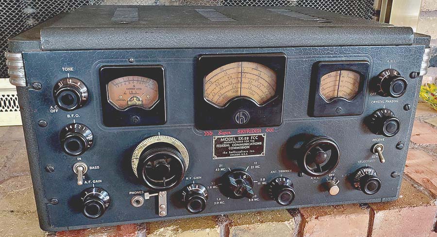
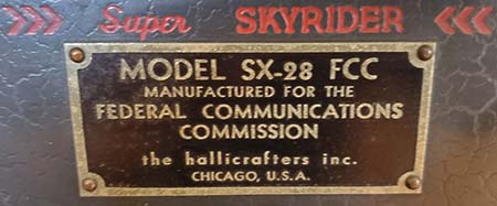
 H-115410(FCC), H-115420, H-115850(FCC), H-116208, H-116219, H-116223, H-116239, H116268, H-116293, H-116332, H-116362, H-116368*, H-116391, H-116418, H-116425, H-116877, H-118962, H-119039, H-119090,  H-119051*, H-120672, H-120692, H-120728, H-120814(FCC), H-120864, H-124230, H-124389, H-124417, H-125569, H-127986*, H-128056, H-128095, H-128195,  H-130170, H-130193, H-132738*(6-41) H-132850, H-136487, H-136508, H-139526, H-142268, H-142317, H-142388, H-142467, H-142501, H-150090, Other Military SX-28 or SX-28A Rack Mounts (not AN/GRR-2) - 4/42 to 9/45:  H-163132(HD), H-169129(HD), 
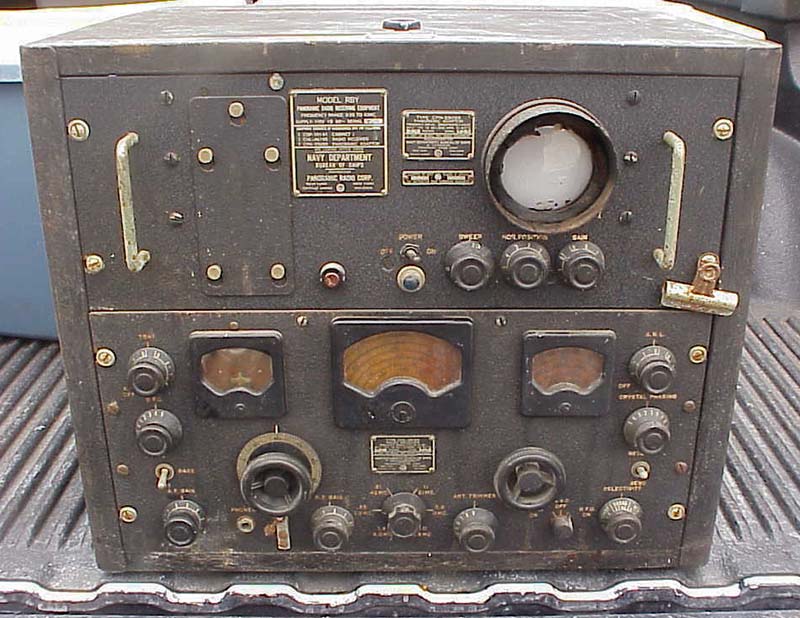
H-169146(?HD ver in std cab), H-181853(RBY-1), H-181856(RBY-1), H-181862 (RBY-1), H-181943(RBY-1), HA-2215, HA-9667(28A), HA-9705(28A), HA-11774(R),
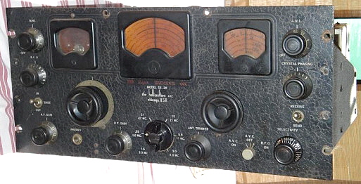
SX-28 WWII - 2/42 to 1/44:  H-151071(2/42civ), H-151071, H-151194 (2/42civ),
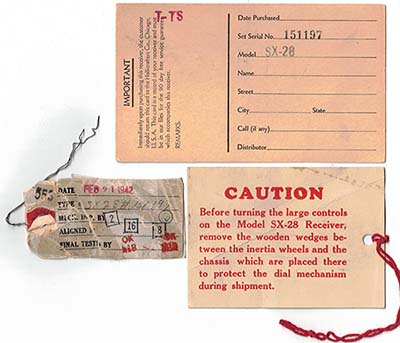
 H-151197*(2/42civ), H-151307*(2/42civ), H-151492, H-152640, H-154424**, H-156776, H-158937, H-158997, H-159006, H-161034, H-162685, H-164727, H-164758, H-164784, H-164953, H-164996, H-165900, H-165949, H-166062, H-167025, H-167187**,  H-167827,  H-167872,  H-167990, H-170548, H-170578,  H-170655, H-170808, H-170912, H-171964 (RCF?), H-172184, H-172381, H-173611, H-173684, H-173791, H-173798, H-173858, H-173999, H-174190, H-174254, H-174256, H-174842, H-175411, H-176307, H-176470, H-177313, H-177442, H-178848, H-180447, H-180455, H-180586, H-180715, H-181157, H-181159, H-181692, H-181426, H-181715, H-181915, H-181958, H-181970, HA-2105, HA-2126, 
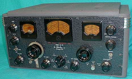
SX-28A civilian without "A" on panel - 8/45 to 9/45:  HA-22033, HA-22114, HA-22184, HA-22267, HA-22658, HA-22950, HA-23069, HA-23114, HA-23121, HA-23349, HA-23367, HA-23374, HA-25272, HA-25562, HA-25583, HA-27742, HA-27755, HA-27808, HA-27852, HA-27888,

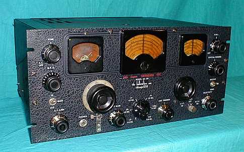
SX-28A WWII - 2/44 to 8/45:  HA-2385, HA-2686, HA-2963, HA-3088, HA-3107, HA-3124, HA-3160, HA-3168, HA-3447, HA-3589, HA-3595, HA-3660, HA-3663, HA-9049, HA-9266, HA-9276, HA-9325, HA-9374, HA-9446, HA-9459, HA-11084, HA- 11089, HA-11299, HA-11240, HA-11346, HA-11509, HA-11513, HA-11776, HA-11877, HA-12324, HA-18969

SX-28A with "A' on panel - 09/45 to 6/46:  HA-25171, HA-27748, HA-30916, HA-30940, HA-30941, HA-30942, HA-31028, HA-31195*, HA-31397, HA-31624, HA-31633, HA-31704, HA-31746, HA-31762, HA-31821, HA-31897, HA-35075, HA-36548, HA-36592 (Rogers-Majestic #5027,)
HA-36686 (R-M #5013), HA-36796 (R-M #5037), HA-36886, HA-36968 (R-M #5011,) HA-53170, HA-53212, HA-53241, HA-53245, HA-53258, HA-53404, HA-53445,

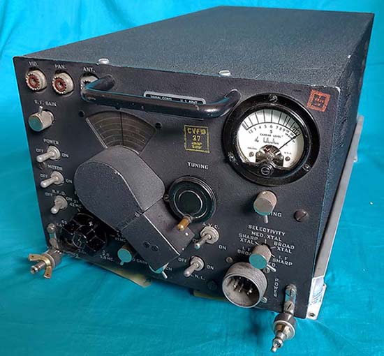
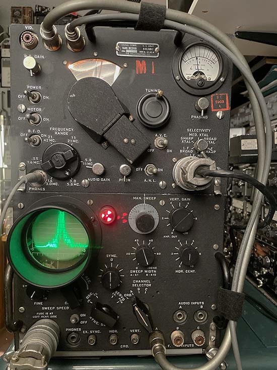
AN/GRR-2 (Mil SX-28A) - 2/44 to 4/44:  HA-2200, HA-2278, HA-2506, HA-2546, HA-2703, HA-2766

R-45/ARR-7: - 39(H), 732(H), 961(H), 1104(H)
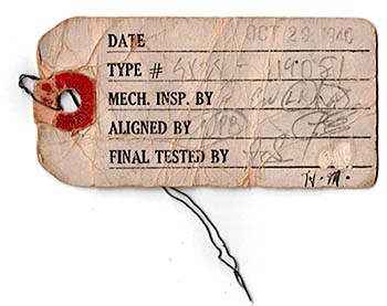
* = Receiver has original dated inspection card        **=Incomplete Receiver         civ = sales to civilians up to 4/42            (FCC) = Built for FCC/RID use

R = Rack mount receiver with proper dust cover         HD = Heavy-duty version of the military SX-28           (H) or (B) = Hallicrafters or Belmont on R-45/ARR-7        

? = Questionable data or combination, unknown owner, not confirmed information                            R-M = Rogers-Majestic Canada


Estimated Production Figures for the SX-28 & SX-28A

ESTIMATING PRODUCTION BY SERIAL NUMBERS: By using the total quantity of serial numbers issued between August 1940 and March 1942, one has about 40,000 numbers. Assuming that SX-28s accounted for about 15% of the numbers assigned, one arrives at a quantity of 6,000 receivers. One has to consider that the SX-25, SX-24, S-20R, Sky Buddies and later the S-27, SX-32, etc., all went into the production serial number use. Small tube-count, inexpensive receivers were much better "sellers" than expensive sets like the SX-28 and accounted for a much larger percentage of production and serial number assignments. An interesting advertisement in August 1941 QST seems to confirm that the SX-28 did not account for a large percentage of orders. The advertisement is for "Bob Henry W9ARA" in Butler, MO, a major ham equipment dealer at that time, (later became Henry Radio.) It shows a telegram from Bill Halligan congratulating Bob Henry on the placing a very large order for Hallicrafters equipment on June 26, 1941. Of the 140 receivers ordered by "Bob Henry W9ARA" only 20 are SX-28s, or about 14%!

From April 1942 through January 1944, manufacture of SX-28 receivers was at a much lower rate than in the pre-war days. However, since many of the less expensive, pre-war Hallicrafters' receivers were now not part of production, the percentage of serial numbers issued to SX-28 receivers increased. It is probable that the ratio of assignment of serial numbers to SX-28s compared to other equipment increased. It is possible that between 30% and 40% of the assigned serial numbers went to SX-28s during this period. Serial numbers assigned during this period should run from H-155000 up to H-185000 and from HA-1000 up to HA-2000. If we assume that 35% of the serial numbers went for SX-28s with about 31,000 serial numbers issued during this period, this would account for about 10,850 SX-28s built between April 1942 and January 1944. This would bring the total SX-28 production to about 16,850 receivers, (6,000 pre-war SX-28s plus 10,850 built during the war for a total of 16,850 receivers.)   >>>

>>>   The use of HA serial numbers started slowly in 1944 and progressed through August 1945 at a slow, steady pace. It seems likely that SX-28A and AN/GRR-2 production was less than 2500 receivers since the "HA" prefix serial numbers were assigned to other receivers such as the S-36 and S-27 (and possibly others.) With the end of WWII in August 1945 and the return to amateur radio production in September, Hallicrafters assignment of "HA" serial numbers increased rapidly. Hallicrafters enthusiasts agree that SX-28A production was somewhat less than that of the SX-28 production. The SX-28A production started around February 1944 with serial numbers around HA-2500. Highest SX-28A serial numbers assigned in June of 1946 are nearing HA-54000. If the SX-28A accounted for an average of 20% of the assigned numbers that results in about 10,300 SX-28A receivers - a reasonable figure. Again, other Hallicrafters receivers were accounting for the remaining 80% of the serial number assignments, e.g., S-40, SX-25, S-38, S-36A, etc. Total SX-28 and SX-28A production should be around 27,150 receivers, (16,850 SX-28s plus 10,300 SX-28As.) However, in a post-war advertisement, Hallicrafters stated that over 50,000 SX-28 and SX-28A receivers had been produced. To achieve this quantity of receivers, nearly 40% of all serial numbers assigned between 1940 and 1946 would have been assigned to SX-28 and SX-28A receivers - not likely. A more reasonable production estimate, that seems to reflect how many SX-28s and SX-28As are encountered today, is around 16,850 SX-28s and 10,300 SX-28As for a "rounded-up" total of 28,000 receivers produced. If special receivers like the AN/GRR-2, the RBY, the R-45/ARR-7 and the special heavy-duty Navy builds are throw-in, perhaps a total of 32,000 SX-28, SX-28A and other related receivers could have been produced.


SX-28 and SX-28A Engineering and Production Changes - 1940 to 1946


1940 Production Construction - August 1940 to Dec. 1940

Though the SX-28 was announced in July 1940's QST, manufacturing didn't start until August, 1940. Most of the major dealers began advertising the SX-28 was "in stock" in September, 1940's QST.


1st RF amp tube is 6SK7 - SN H-116268 uses 6SK7 - changed to a 6AB7 by SN H-119051, 10-29-40

1st RF coils have trimmers (Bands 3-6) - This was probably a schematic error although trimmers are shown on 1940 and 1941 versions. Even the earliest manual's photo of the chassis underside show that no trimmers were used on these four coils.

No Cathode Return bypass condenser C87 (.25mfd) - this may be another schematic error as C87 is found in all early examples of the SX-28 but C87 was not added to the schematic until after 1942

2RF and Mixer coils use air trimmers

Hex head screws used to mount front-end coil chassis

Front panel painted blue-gray - latest SN seen with gray panel, H-125569 - earliest SN with medium black panel H-124417 (12/40) - With these kinds of changes, expect some overlapping in later or earlier serial numbers with gray or black panels due to intermixed stock. 1152 serial numbers separate latest gray panel with earliest black panel. Since SNs were not exclusive it's hard to say just how many SX-28 receivers were built until all of the gray panels were used up. So, expect either color panel to have been used 12/40 thru 1/41.

Front panel texture from 1940 up to late-1943 will have shallow wrinkles or convolutions. These wrinkles were stamped into the metal panel during manufacture.

No panel to cabinet screws used at the top-center of panel, flanking main dial bezel - these mounting screws were being used by SN H-120692 (11/40)

RF Gain potentiometer mounted to chassis - mounted to panel by SN H-124230

1st IF Amplifier Cathode Resistor R-16 is 300 ohms - single resistor with no switching. Switch wafer added probably during second production run in late-1940. More details in fourth listing in 1941 Engineering Changes

T3 tuned with air trimmers (last IF transformer)

C41 listed as 10mfd (1AF Cathode By-pass) - this may be an error on the parts list although it remained listed as 10mfd until the 1943 parts list. Even the earliest SX-28s seem to have a 40mfd capacitor installed for C41

AVC Amp input source from 1st IF Grid

ANL input source from Amp AVC

6SK7 Noise Amp tube - changed to 6AB7 before SN H-124230

T5 design uses variable inductance with only a single adjustment on top of can

CH3 used - choke in ANL, mounted rear chassis next to S-meter pot

Antenna Trim not used on Band 1 and 2

Gear Driven Bandspread Tuning

Selling price was $159.50

Earliest production units went to the FCC Radio Intelligence Division

1941 Engineering & Production Changes

(The following changes are not necessarily shown on the schematic or the parts list in the 1941 Manual)

Front panel paint changed to medium black - end of 1940, latest SN seen with gray panel, H-124389 and earliest SN seen with black panel, H-124417 - Only 26 serial numbers separate this particular change, dating it to Dec. 1940 (though intermixed stock may account for some variability.)

Upper Panel to Cabinet mounting screws (flanking main tuning dial) are being used by SN H-124230 (12/40) - Interestingly, even the earliest cabinets always did have the two tabs to accept these screws however the front panel was not drilled for these two screws until around 12/40.

Cathode Return Bypass (C87) installed on inside front panel by RF Gain control which was moved from chassis mounting to panel mounting - before SN H-124230

1st IF Amplifier Cathode Resistance - Early in production, a switch wafer is added to allow a parallel combination to be switched into the cathode of the 1st IF Amplifier. 600 ohms is parallel with 250 ohms on Bands 1 and 2. 250 ohms on Bands 3 thru 6. Probably to increase the gain slightly on Bands 1 and 2 to compensate for the single RF Amplifier on these bands. Probably installed by late 1940 to early 1941 but first shown on second version schematic (1941.)

AVC Amp input source moved to Mixer Plate

ANL Noise Amp changed to 6AB7, design of T5 changed to variable capacitance with two trimmers on top of can, CH3 replaced with wave trap (CH4 & C55) and ANL input moved to Mixer Plate, C38 deleted (shown on parts list but not on schematic and not installed in circuit,) C37 changed from 100pf  to 50pf, R24 changed from 50K to 100K, SW5 changed from SPST to DPST (ANL switch,) shielded cables to SW5 - all part of the redesigned Lamb Noise Silencer circuit (12-40)

Hex screws used to mount front-end coil chassis changed to Phillips head screws

Red Indicator Set Points on Main Tuning Dial for correct Band Spread Dial calibration - Early dials may have had defective ink used for the red markers. Many early SX-28s will appear without red BS indicators, however close examination of the main tuning dial will usually show some traces of the original red ink. By 1941, the red ink formula was probably changed as the problem of faded red BS indicators is normally not encountered after ~ SN H-128000.

C31, C30 and C29 (Xtal Filter compensation) changed from compression trimmers to ceramic trimmers

Front-end trimmers in RF2 and Mixer stages changed from air trimmers to ceramic trimmers

ANL wave-trap (CH4 & C55) construction changed (early style has a vertical mounted coil, later is horiz. coil)

T3 trimmers changed from air trimmers to ceramic trimmers (last IF transformer)

SN: H-132738 reported with inspection tag on power cord dated June 6, 1941

New manual - still dated 1941 but has recent changes added to circuit description, schematic and alignment procedure (8-41)

Selling price increased to $179.50 (QST 9-41)

Gear driven Bandspread changed to dial cord - mid to late 1941 change, it is still gear driven at SN H-130170 but is cord driven by H-151197 (2-21-42) this was certainly a cost reduction change as it eliminates all of the bandspread gearbox and replaces it with a pulley and dial cord. NOTE: The WWII military AN/GRR-2 (SX-28A) models used the gearbox driven bandspread dial (1944)

1942 Engineering and Production Changes

(These changes are not necessarily shown in the schematic or parts list of the manuals included with 1942 models)

Fuse and fuse holder added - initially mounted atop chassis adjacent to 5Z3, later installed on back chassis apron

Location and orientation of Auxilary Stand-by Switch outlet (looks like AC receptacle) changed when fuse holder is mounted to rear chassis - initially, located above the Phono Input jack with horizontal orientation - later moved next to fuse holder with vertical orientation.

Connector insulators on rear chassis changed from brown R-39 type material to black bakelite (by SN H-158997)

Bracket added to rear of Selectivity switch and screwed to chassis to strengthen mounting

Fiber shaft used for Antenna Trim, eliminates the copper grounding springs used on the earlier metal shafts

R25 and R26 (250K each) replaced with a single resistor, R25 (500K)

Shielded cables no longer have the shields soldered to the RF box corner - SN H-158997

Sleeved shielded cables (to SW-5) that were part of the redesigned ANL and were routed above the wiring harness are now installed next to the chassis and with the wiring harness. There are other minor changes in the wiring harness. A sleeved braided cable connects the 1st RF Amp section shield to the rear of the main chassis (mounted with screws and nuts on each end.) Seen on SN H-158997

Antenna Trimmer circuit modified to have C6 (Ant Trim) functional on Bands 1 & 2 (required a new Band Switch wafer to be added at the rear of the assembly) - This change appears by SN H-158997 (ca. 5-42) but is not on SN H-151197 (2-21-42)

Amplified AVC modified to allow a lower AVC voltage to be used on the RF amplifiers on all bands except Band 1, which still used the higher AVC voltage (required a new Band Switch wafer to be added) - ca. mid-1942, not on SN H-158997

1st IF Amplifier Cathode resistance changed to a series combination switched in on Bands 3, 4 and 5. Cathode R of 250 ohms unchanged in Bands 1, 2 and 6. Probably to compensate for gain changes due to single RF amplifier on Bands 1 and 2 and high frequency gain roll-off on Band 6.

Manual updated with new schematic and under chassis photos to reflect recent updates from 1942 - Part values are shown for capacitors inside IF transformers in new schematic - This manual probably dates from August 1942 (the previous updated manual was dated Aug 1941 and the initial manual was dated Aug 1940)

There is a possibility that the front panel paint was changed toward the end of 1942 - SN H-161034 has a bluish-gray-black (SX-28A color) front panel with light texturing

1943 Engineering and Production Changes

Condenser box cover modified by enlarging the tube cover panel for better access to tubes (seen on SX-28s SN H-167827, H-167872)

Power transformer has a 115-230 "slide switch" added to the top cover to allow 115vac or 230vac operation - found on many SX-28 and SX-28A receivers but only official designation is "SX-28-U" with the "U" standing for "universal" implying that the receivers could be operated overseas or stateside.

A louvered condenser box cover, similar to the SX-28A cover, started to be used by mid-1943 (seen on SX-28s SN H-173611, H-174842, HA-2105, HA-2126) - this cover is mounted to the condenser box with screws (for comparison, H-172381 has the earlier "screened" condenser box cover)

Front panel texture changed to deeper convolutions, painted "bluish-gray-black" (seen on SX-28s SN H-172381, H-178848, H-181715, HA-2105, HA-2126)

Knobs for MAIN TUNING and BANDSPREAD changed to "webbed" style (SN H-181958, HA-2105, HA-2126)

Some of the bandswitch knobs were made from a Plascon casting that had a tendency to warp or crack or do both simultaneously. Some bandswitch knobs apparently were bakelite castings that seem to age without too many problems but expect the Plascon knobs to be in rather poor condition. The Plascon bandswitch knobs tend to be on early production units. The other SX-28/Hallicrafters knobs are bakelite castings that seem to age well. The silk-screened metal skirts can oxidize rather easily in humid storage areas.

Serial number "HA" series starts (~12-43 to 1-44)

1944 Engineering and Production Changes

SX-28 production stopped (~ 1-44 to 2-44) to introduce SX-28A into production

SX-28A production starts (~3-44 to 4-44) - earliest production units were the AN/GRR-2 receivers, earliest SN HA-2200 (AN/GRR-2)

SX-28A Manual dated April 10, 1944

Most parts changed to JAN type values

Tube IDs changed from engraved on sockets to painted ID on chassis

Louvered lid for condenser box changed to clip-on mounting

Auxiliary Stand-by Relay Switch outlet on rear chassis eliminated - connections are now in the octal accessory socket on the rear chassis

Front-end coils changed to smaller "Hi-Q, Micro Set" types, coil chassis sheet metal changed for new coils along with wire routing changes, eliminates old RF box construction

Amplified AVC transformer has added 25pf capacitor in parallel with secondary to prevent oscillation

1st IF Amplifier Cathode Resistance - values changed from 1800 ohms to 1200 ohms and 1200 ohms to 1000 ohms. These values are in series with 270 ohm (changed from 250 ohms) Cathode resistor on Bands 3, 4 and 5. Possibly changed to conform with JAN values.

The above changes were in place when the SX-28A production began and are on all examples found

1945 Engineering and Production Changes

Glass in dial windows changed to Plexiglas on some models (seen in rack mounted models)

Shafts for ANT TRIM and XTAL FILTER PHASING changed to plastic on some models

Designation on front panel changed to "SX-28A" (earliest SN seen with "SX-28A" on panel - HA-25171 ~09/45) HA-31195 with "A" on front panel rpt'd with inspection tag dated Oct. 8, 1945. A lot of inter-mixed stock in September's production. Hallicrafters probably wanted to be sure that all SX-28A receivers sold for Christmas 1945 (Fall sales season) would have the "SX-28A" designation on the front panel.

1946 Engineering and Production Changes

Selling price listed as $223.00

2nd RF Amplifier tube changed to 6AB7 (seen on HA-25171, HA-53212)


SX-28 and SX-28A Variations Seen or Reported

The FCC-RID Variations:  The typical FCC receivers had a metal tag mounted on the front panel or on the back of the receiver for FCC identification. These receivers also carry the standard Hallicrafters' serial number tag with standard Hallicrafters' serial number assigned. The FCC versions are typically from the first production run of SX-28s and usually are SN: H-115xxx, although there is one reported FCC version from the second production run with SN:120814. These receivers were first used by the FCC's RID (Radio Intelligence Division) to listen in or find enemy spy rings in the US. These SX-28s were installed in automobiles with a directional loop antenna on top of the roof. By having roving DF abilities, the RID could triangulate a signal and determine its location. There were some later versions that were built for FCC monitoring posts where several receiving stations would be in operation. Each operator would be using earphones to prevent listening interference to an adjacent monitoring station. Since the audio requirements were minimal, the Push-Pull audio output 6V6s were usually replaced with a single-ended 6V6 audio output. The unused 6V6 tube socket mounting hole has a push-in metal plug installed. (Single 6V6 info thanks to K4ERR.)

There are variations of the FCC SX-28 that may have been modified by the FCC to accomplish diversity reception or other special requirements. The FCC diversity set-ups appear to use two SX-28 receivers, one with the S-meter removed and the other with the bandspread removed. This observation is based on a photograph that appeared in CQ magazine in the 1940s. George Sterling, who was head of the FCC during pre-WWII and WWII, wrote a detailed report on the RID's function and successes that included many photographs of banks of SX-28s that were in use by the FCC. Although other receivers were used, it appears the RID was almost exclusively using SX-28s for their intercept and monitoring. The WWII-1945 Hallicrafters' ad artwork shows how the SX-28 was integrated into the RID monitoring stations. Note the Dictograph machine (a wax cylinder recording machine) between the receivers. The grab handles pictured on the receivers are sometimes found on examples today. The metal "FCC" tag on the front panel is shown in the artwork and is typical of those SX-28s that were used by the FCC-RID.

SX-28 Navy Versions:  The rack mount, standard Navy version is from late 1943. It does not use the standard front panel but has a black wrinkle finish panel with white nomenclature. No "Super Skyrider" or "hallicrafters" on front panel - a military ID plate is mounted on the panel instead. Heavy duty construction in some areas under chassis. Cabinet is similar to AN/GRR-2. These receivers are issued standard Hallicrafters' serial numbers carried on the tag mounted to the rear chassis of the receiver.  There was also the RBY, a Navy piece of equipment that used a SX-28 combined with a Panadaptor with 3" CRT. The SX-28 has an SO-239 installed on the back apron of the chassis to connect the Panadaptor. The version I saw also had a buffer circuit assembly on the antenna input to allow multiple receivers to use a single antenna. The SX-28 receiver has a military tag where the "SX-28" ID is on the front panel and it identifies the receiver as CHL-46195. The panel is black wrinkle paint - not the standard panel. This receiver did have the standard Hallicrafters serial number tag installed on the rear of the chassis with the number H-181853, indicating late 1943 production. The RBY was an earlier, military version of the S-35.

Canadian Versions:  Distributors like Rogers-Majestic sold SX-28s in Canada. These receivers will have the original Hallicrafters' serial number tag with the standard Hallicrafters' serial number assigned and an additional serial number tag with a distributor-assigned serial number installed by the distributor in Canada. Also, the receivers usually have a tag or decal from CSA, which is similar to USA's UL.

SX-28U and SX-28AU: Usually were special order receivers with a dual primary power transformer for operation on either 115vac or 230vac. The transformer has a slide switch on top of the transformer cover for selecting the operating voltage. Apparently this was popular as many SX-28s and SX-28As are equipped with the dual primary power transformer but there is no special designation shown anywhere on the receiver when it is so-equipped.

Send-Receive and Bass In/Out Switches:  Short handle, ball-end toggle switches used on SN H-130170 - long handle toggles were normally used. The exception is the AN/GRR-2 which also used ball-end toggle switches.

T3 inductively tuned: Seen on SX-28A Rack Mount SN HA-11774. Probably a skillfully executed repair of T-3 that installed a replacement IF transformer into the original T-3 housing.

Custom Front Panel Colors:  Supposedly, white panels were needed aboard hospital ships however one has to ask - why? and who did the painting? Silver panels turn up from time to time but these seem to be panels with the original paint stripped off. "Original" seems to have a different definition to some owners but claiming a refinished panel is "original" because it's an old paint job doesn't mean it came from the factory that way. Custom finishes were sometimes required in certain installations, sometimes it was personal preference but always the end user was responsible for this painting operation. Though the custom panel finish may appear old and original it certainly is an "end user paint job" and it is not "from the factory original." Would Hallicrafters "custom finish" an SX-28 "on request?" It would require procuring special paint that most likely wouldn't have been done for just a single receiver. Besides, the panels were made by Crowe Manufacturing for Hallicrafters and Crowe would have to do the special paint job - unlikely, unless it was for a large order and there just isn't the evidence of any quantity of custom finished panels.

White Tuning and Band Spread Dials - I recently received an e-mail photo of a restored SX-28 that had been fitted with modern reproduction "white dials." This is the only SX-28 I've ever seen with white dials installed and they were, of course, repro dials. Were white dials ever installed on the SX-28? On standard production receivers the answer is no. IF any WWII-vintage white dials are authentically installed on a WWII vintage SX-28, they are an anomaly that could possibly be attributed to the end-user installing non-OEM parts. Who would have made these dials? Crowe Manufacturing? The Signal Corps? An unlikely scenario in either case that would then account for the absence of any confirmed vintage examples.

SX-32 & S-35  - the SX-32 is very similar to the SX-28 but it doesn't have the Lamb Noise Silencer or BASS IN-OUT toggle switch and uses 13 tubes. It was priced at $149.50. The SX-32 was introduced in July 1941 and was probably only produced until Dec 1941, less than six months of production, which is probably why the SX-32 is so scarce.

The S-35 was advertised as a "panoramic receiver" and was an SX-28A with a panoramic adaptor with 5" CRT mounted in a single, tall table cabinet. Based on the older RBY receiver. The 1946 price of $375 probably kept most S-35s out of the amateur's shack.


Restoration Methods & Suggestions

MANUALS: If you don't have a manual, get one. Remember, there are several variations in the manuals with different schematics and different under chassis layouts (for alignment.) The earliest manual was printed on "slick" paper in August of 1940 and is numbered "07292840." This manual has the earliest schematic with the two 6SK7 RF amplifiers. The next version is from August of 1941 and is printed on standard matte paper. It is numbered "01092841" and has most of the 1941 changes shown on the schematic and in the circuit descriptions. The schematic and alignment information in Rider's Perpetual Troubleshooting Manual VOL. XII is the same as "01092841" Hallicrafters' manual. Most reproduction manuals that are available are broken down into "standard" early version (01092841), mid-production version (no number-1942) and SX-28A (April 10, 1944.)

Most production SX-28s won't agree entirely with any manual as the engineering changes were incorporated immediately while documentation usually took some time. Sometimes addendums turn-up, so Hallicrafters was attempting to keep their documentation current. The mid-production manuals are sometimes dated "1943" but many manuals at this time weren't dated at all. Many of the 1943 manuals have thick covers rather than standard paper (more variations!) If the schematic shows the AVC and ANT TRIM changes, then it is a mid-production manual from August, 1942 (or later.) There is one 1943 version manual that erroneously shows T-6 as a dual variable-C adjustment transformer. Other 1943 manuals will show T-6 correctly as single variable-L adjustment transformer. The SX-28A manuals are so-marked and Rider's VOL. XVI contains a schematic and alignment information on the SX-28A.

There is also an AN/GRR-2 (military SX-28A) manual that has much more detail than its civilian counterparts. The AN/GRR-2 manual is TM11-874. Unfortunately, TM11-874 has many errors that never had the opportunity for correction since there was only one production run of AN/GRR-2 receivers. A few obvious errors in the AN/GRR-2 schematic,...R17 (1K) and its connection to pins 4 and 5 of the 6L7 first IF amplifier are missing. This part of the circuit is shown correctly in the standard SX-28A manual's schematic. Also, in the voltages shown in the troubleshooting table, the 1st RF amplifier screen voltage is shown as +270vdc when it should be +170vdc. Again, this voltage is correctly shown in the SX-28A civilian manual. It's best to have several versions of both the SX-28 and SX-28A manuals as this allows verifying questionable data in one manual by checking a different version.

WORKMANSHIP: The SX-28 or the SX-28A are not easy receivers to restore. There are around forty paper-wax capacitors to replace along with five electrolytics. Many of the capacitors are difficult to access and several parts need to be dismounted or disassembled to remove old capacitors and install the new capacitors. Additionally, many of the resistors can't be measured accurately while in the circuit. This requires that one end be unsoldered for accurate measurement if the resistor is suspect. How well the receiver is going to work after its rebuild depends on the level of workmanship (or skill) of the rebuilder. Checking yourself and rechecking what you are doing is second nature to experienced technicians. Quality soldering technique again is something acquired with experience. Real SnPb solder must be used for quality work. Rushing through the job is not recommended as this leads to mistakes and poor workmanship. All of these are important skills that are necessary when reworking (or considering reworking) any receiver as challenging as the SX-28 or SX-28A.

ELECTRONICS & COMPONENTS: For best reliability, all paper-wax capacitors and all electrolytic capacitors should be replaced. From the manual, go through the parts list and order the capacitors in advance. Having them all on-hand makes the job much easier. Whether you use "orange-drops" or "yellow jackets" is up to you. Both types are excellent quality caps that are much better than the originals were,...even when they were new. I find it easier to work a section at a time starting at the power supply then moving to the IF/ANL side and then to the front part with AVC/DET and BFO circuits. Also, I install the electrolytics inside the original cans. This is just for aesthetic reasons and results in a nicer looking job.

I usually don't re-stuff the paper-wax capacitors in SX-28s or 28As because there are plenty of original examples of these receivers around so preserving the original appearance of the under side of the chassis is not as important as it is with other, more scarce equipment. However, a purist would go ahead and restuff the paper caps to preserve to original under-chassis appearance. If resistors need to be replaced, the purist would use vintage originals that haven't drifted in value. Many SX-28s made during WWII had ERIE brand resistors installed. While many brands of resistors do value-drift over the decades, it seems that the ERIE brand is particularly susceptible to drift. But, check all resistor values regardless of brand. Any other defective components would be replaced with good condition original parts. This makes a restoration difficult and very time consuming but the end results are worth the effort.

As time goes on and more and more SX-28s are restored with new parts it will become more important to preserve the authentic appearance of the underneath of the SX-28 chassis. So, why not start now?

RF BOX CAPACITOR REPLACEMENT - SX-28: There are usually eleven capacitors that should be changed in the RF box. Though some people can work around with special tools to replace the caps without disassembly, I can't imagine how to accomplish it without breaking something. Disassembly of the RF box is necessary, along with removal of both RF coil chassis. This will require removal of the bandswitch shaft, unsoldering several connections to the tuning and bandspread condensers, unsoldering wires from the coil chassis to connections in the receiver chassis and a few wires that interconnect between the coil chassis. Usually the Mixer coil chassis can be worked on while still in place, however a long tip soldering iron will be required to reach the chassis connection on one of the capacitors on earlier versions. Read the procedure on restoring an SX-28, in particular the section on rebuilding the RF box, at Phil's Old Radios (link provided in references, bottom of page.) This is a step-by-step guide that can be followed as you rework the RF box. Remember, this is a guide - not all SX-28s are exactly like the one described in that procedure. Watch the height of the caps when mounting the replacements as clearance is tight. I use a Makita driver to disassemble the RF box - it's a lot faster and the bits seem to fit the Phillips head screws better. The early SX-28s used hex head screws to mount the coil chassis. These make clearance between the coils and dividers very tight so care has to be taken to avoid damaging the coils. A straight sided, .25" hex, driver bit extension can be used as a nut driver for extra clearance. Photo right of the underside of SX-28 SN H-119051 showing the construction of the RF box and the layout of the various coils and trimmers. There are several noticeable differences in this early model, e.g., the chassis mounted RF Gain control, the absence of the shielded cables for the ANL switch, air trimmers used in the 2nd RF and Mixer coil assemblies. Also, noticeable are the SBE Orange Drop replacement capacitors.

SX-28A FRONT END: The SX-28A is similar to rework, that is, requiring removal of the rear bandswitch shaft, unsoldering of the condenser connections, removal of three to four wires per coil chassis terminal board and a few wires that interconnect each section to allow removal of each assembly for capacitor replacement. The coils are mounted to fiber boards that are screwed to brackets that are part of the coil chassis of each section. The Second RF and Mixer coil chassis have two fiber boards with three coils mounted on each board. The First RF chassis has the four coils mounted to brackets that are part of the coil chassis. Unlike the SX-28, the tube sockets are mounted to the coil chassis and this construction has some of the capacitors not visible (since they are under the fiber boards) until the coil chassis is removed. While it might be possible to leave the coil chassis mounted and try to remove each fiber board to access the capacitors, it is easier in the long run to just remove both RF chassis, along with the Mixer chassis, for capacitor replacement. Even then, the 2nd RF coil chassis requires dismounting both fiber boards to access two of the paper-wax capacitors. The SX-28A has no RF box per se, as the coil chassis make up the entire front-end shield assembly when mounted to the receiver main chassis. Also, the band switch shaft has a coupler between the oscillator section and the mixer section so only the rear band switch shaft needs to be removed. So, even though the SX-28A is considered an easier candidate for front-end rework, don't be surprised if it takes just as long and is just as difficult as the SX-28 front-end. Photo right shows the underside of SX-28A SN HA-11774 showing the construction of the new Hi-Q Micro-set coils and the coil chassis that comprise the shielding when the front end is completely assembled. Note the replacement capacitors. Also, note that the original power transformer was replaced sometime in this receiver's past. The coax from the mixer output to the accessory plug for operation of a panadaptor (not recommended as it "loads down" the Mixer and reduces sensitivity above 10mc.)

This receiver is owned by KØDWC - Dayton, Nevada

grr2coils.jpg (36876 bytes)

2rf28sm.jpg (13630 bytes)

photo left:  A close-up of the 2nd RF coil assembly from an SX-28 removed for rebuilding. Shown are the large coils that are characteristic for that model. Since this is an early version, note the air capacitor trimmers.

photo right:  This is a close-up of the 2nd RF coil assembly from an SX-28A removed for rebuilding. Note the difference in the size and shape of the Hi-Q Micro-set coils compared to the old style coils of the SX-28. Shown are the fiber boards that the coils mount to and the tube socket that is part of the coil assembly. Though they can't be seen in the photo, the condenser leads are underneath the assembly.

28a2rf.jpg (16500 bytes)

GEARBOX:  The early SX-28 gearbox will have two separate gear trains that operate the main tuning and the bandspread dials. Later SX-28s and all SX-28A receivers only have a complete gear train on the main tuning and have a dial pulley and cord that operates the bandspread with a minimal number of other parts. The AN/GRR-2 uses a gearbox similar to the early SX-28. In most cases the gearboxes are robust in construction and rarely does anything actually break inside. However, they are victims of too much grease applied in the wrong places and sometimes sticking anti-backlash gears caused by an accumulation of dirt. In most cases, poor operation can be corrected with a thorough cleaning. After removing the gearbox as a unit, flush all of the gears with a constant stream of WD-40 from a spray can. Use the WD-40 liberally (it's cheap) and use a small long handle paint brush to brush off the grease and dirt. This will result in very clean anti-backlash gears that operate correctly. Fortunately, the main shaft and bandspread shaft bearings can be accessed without total disassembly of the gearbox. The main tuning and bandspread shaft bearings that have the greatest influence on the operational feel of the tuning. These bearings have around 13 ball bearings of .0937" diameter on each end of the shaft with the drive gear centrally mounted. On the back of the gearbox are located the tuning shaft weights which need to be removed. Note that the main tuning shaft weight not only has set screws but also is threaded onto the end of the shaft. This is to allow precise setting of the "slip clutch" which prevents damaging the couplers by over driving at the tuning condenser end stops. At the rear of the shaft bearings is a lock nut and the threaded bearing housing. These can be removed and this allows access to the ball bearings and the housing. When the rear bearing cup is removed the shaft can be moved slightly to the rear to allow access to the front bearing for cleaning. It's a good idea to use a small clamp on the the split-gear that engages the main shaft gear to assure that you don't loose the anti-backlash preload. Clean and repack both bearings with wheel bearing grease. Unfortunately, the old "stringy" yellow wheel bearing grease that was used originally is difficult to find (unless you want to import it from Egypt.) Sometimes it can be found listed as "Sodium-based Grease." >>>

>>>  If you can't find the "stringy" grease then use the thickest wheel bearing grease you can find for repacking and then re-fit the threaded bearing cap. Be sure to use the same number of ball bearings in each cup that were removed. Sometimes this total varies by one ball bearing but what was installed is the correct number. Adjust the bearing end thrust until you just begin to not feel any end-play. Replace the tuning shaft weight and the tuning knob and try the operation and feel. Adjust the bearing further if the operation is too loose or too tight. Adjust the main tuning shaft weight so the center shaft operates the gear train but, if the gears are held with your fingers, the shaft slips. If the gearbox is the old style then proceed to the bandspread side which is more or less identical to the main tuning side. The anti-backlash gears all run on a single ball bearing which can be lubed with light grease applied with a syringe or other applicator that can get into tight quarters. The same applies to the ball bearings on the dial drive gears. I have deliberately avoided total disassembly of the gearbox in this description because of the difficultly of reassembly. There are eight anti-backlash gears (early boxes) that have to be held in the "loaded" position with small clamps while the gearbox plates are put back together. This is a difficult operation (yes, I've done it - twice) and should only be attempted if absolutely necessary - like replacing a broken gear or similar operation. Casual disassembly of the gearbox is not recommended. However, if you do need to perform a total disassembly and reassembly the gearbox, Doug Moore KB9TMY has written a thorough article on the rebuilding of the SX-28 Gearbox. It is currently available at Phil's Old Radios' website. Here's a link: SX-28 Gearbox Rebuild

IF/RF ALIGNMENT: Though re-capping is certainly an important facet of the electronic rebuild, a thorough and careful alignment is what really allows the rebuilt SX-28 to perform to its full capabilities (along with a resonant or matched antenna.) The manual's alignment instructions are tedious and never changed (after 1941) throughout the SX-28 and SX-28A production. Even TM-11-874 for the AN/GRR-2 uses the same procedure. Essentially, the procedure tells you to "rough" align the IF at 455KC and then determine the exact crystal frequency. Realign the IF at this frequency and balance the crystal filter response for its three positions using the trimmers provided. If you have aligned communications receivers before, the procedure will be a familiar process. A resistive load is required for alignment of the 1941 Lamb Noise Silencer (the earlier version does not require a load for alignment.) The manual references the color of the wires for placement of the load but unfortunately most SX-28 wiring has darken considerably and it is difficult to tell where the load is placed except by referencing the schematic. The amplified AVC has to be aligned to the IF. As with any receiver alignment, always keep the signal generator output amplitude level as low as possible.

On the two top bands it's very easy to align the LO tracking to an image if the sig gen output amplitude is too high. Check the tracking and if the dial accuracy is off significantly you might have the LO aligned on the image. Example: if when checking Band 5 tracking, 15mc WWV actually tunes at about 15.9mc but the band edges are okay, your LO is on an image. Proper tracking should have the band edges close (12mc and 20mc on Band 5) and 15mc WWV should be within one division on the dial index. The better your alignment skills are and the better your equipment is, the better your SX-28 will perform after alignment.

Sometimes the slugs on the Hi-Q Micro-set coils used on the SX-28A are "glued" in place making adjustment difficult. It's a good idea to check the adjustability of the slugs during the recapping of the receiver while the coil sets are out of the receiver (you're going to do an alignment later anyway,...right?) Normally, the "glued" slugs will show excessive wear in the slot for the adjustment tool. You have to proceed carefully if adjustment is necessary as the slugs break easily. Sometimes it will be impossible to move a stuck slug without breaking it or breaking the coil mounting, which is not an option. Try a small amount of localized heat (small soldering iron tip on slug) to loosen a stuck slug. After about 10 seconds you should see the glue begin to bubble near the edge of the slug. Alternately, keep trying to move the slug and then apply the heat. Eventually, the slug should loosen. If the slug is hopelessly stuck and you have access to a "parts set" then the coil with the stuck slug could be replaced. 

S-METER POT:  A common problem with SX-28s is the S-meter potentiometer. Quite a few will show a short to chassis. In most cases these are easy to repair. Remove the pot from the circuit and the chassis. Remove the rear cover from the pot. This is a tight press-fit but if you support the pot body in a small vise, the rear cover can be removed by using a small flat metal drift and a small hammer. Don't be too aggressive, the cover will come off with gentle taps. Once the rear cover is off, you will probably find that the rear cover's inside metal plating has peeled off and several strands of metal plating are all around the windings of the pot. These can be blown out with air or brushed out with a small paint brush. Once the strands are removed the pot will no longer show a short to case (or chassis.) Reinstall the rear cover (after wire brushing the remaining plating off of the inside of the cover) and reinstall the pot into the circuit and chassis.

AUDIO OUTPUT TRANSFORMER: The audio output transformer used in the SX-28 and SX-28A was unique to Hallicrafters' designs. It is 9K Z CT on the plate side and 100, 500 and 5000 ohms Z on the output side. Nowadays, quite a few SX-28s are missing their original audio transformer and a universal replacement has been installed in its place. The replacement will not have the correct output Z and will compromise the correct operation of original Hallicrafters' speakers that have the 5000 to 8 ohm Z matching transformer built-in. Try to find a functional original but in the meantime, Hammond Mfg., Ltd. manufactures replacement audio transformers that are to original specifications. Its installation will provide the correct matching Z for the P-P 6V6 amplifiers and allow the SX-28 to be used with an original Hallicrafters' speaker, such as the PM-23 or R-12. The physical size and construction are identical to the original, however the appearance is slightly different as one would expect. In operation, it provides excellent audio that is nearly identical to the original transformer. NOTE 2021: Check the Internet for current availability and sources. Hammond Mfg Ltd is a Canadian company but they have several distributors and outlets in the USA. All ordering can be accomplished online.

ALIGNMENT OF THE BAND-IN-USE INDICATORS - These just seem way too "Rube Goldberg" to have been anything other than a "last minute" solution for band-in-use indicators (probably a requirement for government purchases.) Dual dial strings are wound around the bandswitch shaft and routed up to pulleys that will raise and lower spring-loaded pointers that utilize the dial lamp to cast their shadow onto the back of the Main Tuning dial and the Bandspread Dial. Most of the time the dial strings are broken or missing. A stringing guide is NOT in the manual but it isn't too difficult to figure out. Make sure the pointers are very close to the back of the dial for a "sharp shadow" indication. Once you have the string and pulley system pretty close you can use the adjustable "swing-arm" pulley to fine adjust the pointer position. These "shadow pointers" aren't very accurate and generally will be off in their indications, especially at either end of travel. It's just a really crude system that was obviously a "last minute" solution that just sort-of works.


Authentic Cosmetic Restoration

If ever there is a subject that will produce endless controversy, it will be "what is correct" or "what was original" for the paint color, nomenclature, dials, etc.,...and this is for just about any object that is in need of cosmetic restoration. Of course, I advocate that, whenever possible, only cleaning of the original finishes should be performed. This preserves the originality for future reference. However, sometimes the cosmetics are in such terrible condition a restoration is required for an acceptable appearance. What is presented here is a guide for doing an authentic cosmetic restoration of the SX-28 that conforms to how the receiver appeared when it originally left the Hallicrafters' plant. 

CABINET: Many SX-28s are in fairly rough condition after years of storage in less than ideal environments. Before stripping paint, take the receiver out of the cabinet and remove the front panel. This will allow a constant flow of water and cleaning liquid to flush away the years of grime and dirt that are ingrained into the wrinkle finish of the cabinet and panel. I use a large paint brush to work the cleaner into the convolutions of the wrinkle finish and then flush with water. It will probably take two or three sessions to get the cabinet and panel thoroughly clean. Sometimes, if the dirt and grime is stubborn, I'll use a soft brass brush (like a suede brush) to work the dirt out of the convolutions. Don't use excessive brush pressure but the original paint is very tough and can stand up to this aggressive cleaning without any problems. When everything is clean and dry it is a lot easier to assess what needs to be done. Many times, after a good cleaning, it is apparent that just a touch-up will fix what are now just minor paint problems. I use artist's acrylic paint to mix an exact match for touch-ups. Remember that you can't get the correct color "off of the shelf" because every SX-28 has aged somewhat differently and the color will vary from cabinet to cabinet. If you have the color matched at a paint shop, it won't be wrinkle finish. It will be fine for touch-ups but not for a complete repaint. After touch-up, apply "3 in 1" oil with a clean cotton cloth. Wipe off the excess. The cabinet will look like it's almost new.  >>>

>>>  If you have cabinet paint that is beyond saving, there are automotive paint shops that specialize in various types of powder coating that can sometimes give good results (but often they don't.) Sometimes their paint jobs can look fairly close to wrinkle finish (at least at a distance.) All of the powder coated SX-28 cabinets I've seen have been painted black, which is incorrect. The one gray wrinkle powder coat job I saw was on a PM-23 speaker cabinet and the color was more blue than it was gray leading me to believe the painter was either careless or color-blind. Definitely have the powder coater provide some samples of his work before having him paint your cabinet. They can do good work but often their schedules have them hurrying through jobs that should require attention to details.

I've painted two SX-28 cabinets in the past. I did these restorations when Illinois Bronze was still in business and was still supplying their "French Grey Wrinkle Finish" paint. Illinois Bronze was purchased by Pittsburgh Paints and that was the end of the availability of that grey wrinkle finish (and Illinois Bronze.) For quite a long time, finding gray wrinkle has been difficult. At present it might be possible to find VHT Gray Wrinkle Finish paint. It's sometimes carried by auto parts dealers and auto speed shops. I found a couple of cans from a large auto parts-speed shop dealer selling on eBay. The VHT gray wrinkle has a lot of brown in the gray. It's high quality paint although the color is slightly off from the SX-28 cabinet gray but it will still look very authentic.

USE ALL OF THE SCREWS:  When reinstalling the receiver chassis into the cabinet, be sure to install all of the screws that secure the chassis to the bottom of the cabinet. If the screws are left out (which is how many unrestored SX-28s are found) overall stability of the receiver suffers. This is a mechanical issue and without the screws any movement of the cabinet results in movement of the chassis. When all of the screws are installed and tight, the SX-28 chassis is rigidly mounted and the cabinet can be "jarred" with very little (if any) frequency change resulting. Screws for mounting the receiver into the cabinet are 10-24 pan head thread-cutting screws. Under the screw head is a fiber washer to protect the panel. The original screws were black oxide coated (difficult to find in black oxide - you can paint the "easy to find" zinc-plated screws flat black which looks close to original.)

FRONT PANEL: The front panels are "dark" gray-blue on very early SX-28s. This same color was used on many Hallicrafters' cabinets, like the S-20R. The front panel color was changed to a "charcoal" black in December 1940 and remained that color until late 1943 when the new, heavily textured front panel was introduced on some of the last SX-28s produced. There is some evidence that the front panel paint color was changed sometime before the heavy textured panel introduction as at least a couple of SX-28s have turned-up with the bluish-gray-black paint on front panels with the light texture (SNs H-161034 and H-173684.) This same color was also found on a 1944 AN/GRR-2 receiver panel. In comparisons with other, later SX-28A receiver panels, it does appear to be a slightly different color, however more examples of later, post-war SX-28As have to be examined to determine if this color was used after the end of WWII. Usually, the late-1945 to 1946 SX-28A front panels are sort of a gunmetal-type blue-black. The color difference between the WWII panels and post-WWII panels is very subtle and really only noticeable when compared directly with other panels.

When a poor condition panel is encountered and it is necessary to repaint, a good condition original panel is always helpful for comparison to available colors for matching. In most cases the back of the panel will provide the best condition source for the correct color match. Use high quality automotive paint that is "color matched" to the original panel paint for the most accurate and best quality results.
 

NOTE: I cannot stress the following point enough when restoring SX-28/28A front panels. The nomenclature on the panel is NOT white but is correctly MATTE SILVER. Careful examination of a good condition, clean, original panel will show that the fill color is definitely matte-silver. Over the years, the silver fill paint will have discolored with smoke and other "grunge" so that it might look "smoky-white" but - look closely - it is actually silver (use Artist's Acrylic "Silver" paint for the nomenclature fill,...dull the silver to a matte look with a "touch" of Mars Black in the mix.) Many "hamster-restorers" just don't care whether the panel is correct - as long as it's new paint. The front panels were never jet black with white nomenclature. For authentic restoration of the SX-28/28A the front panel color should be determined by inspection of the back side of the panel and the paint color matched accordingly. Nomenclature is matte-silver with the exception of "Super SKYRIDER" which is filled with gloss dark red (not fire engine red) paint.

sx28nom.jpg (12785 bytes)

photo above:  A close-up showing the matte silver paint fill used for the nomenclature of an excellent condition original SX-28. A white card was placed in the photo as a reference (although most monitors have a difficult time reproducing silver colors.) Note the red is a very dark shade.

SX-28 Dials - Cleaning, Dial Color Controversy and the White Dial Myth

DIAL CLEANING: Never let excessive moisture get on the front of either of the dials or the meter scale. The ink used is somewhat water soluble and if aggressive wet-cleaning is attempted it will be the end of the dial nomenclature. NEVER use "Windex" or similar ammonia-based glass cleaners on the nomenclature side of the dial. These types of cleaners dissolve the ink almost immediately. If the dials are in good condition, use only a dry camel hair brush to dust off the surface - lightly. The front of the dial can be lightly wiped using a clean soft flannel cloth BUT do this lightly and watch the nomenclature closely to see if there's any "thinning" from the wiping action. Only do the flannel cloth wipe to remove the dusting brush marks.

If the dials are severely discolored due to smoke and dirt, their appearance might be improved using a "foaming" plastic cleaner. These plastic cleaners contain very little water and no ammonia. I have had some success using this type of cleaner applied with a cotton cloth (never use paper towels on plastic.) The cloth should be sprayed, not the dial. With the cloth slightly damp, apply the cleaner gently. Be careful! This has to be performed with a light touch while watching the dial nomenclature for any thinning. Avoid the red BS indicators. You will only be able to remove some of the oxidation - don't be too aggressive or you will begin to remove the dial nomenclature. The back of the dials and the meter scale can be wet-cleaned and it will help the overall brightness when illuminated. Careful cleaning will help "even-out" the discoloration due to dirt and smoke.

This cleaning method won't really help with the discoloration due to exposure to light. The photosensitive color change is actually into the plastic and it's impossible to return the dial to its original color. Most of the dials have darkened considerably over the years and aggressive cleaning will surely damage the dial nomenclature. It is unfortunate but that was the type of plastics that were around in 1940. The correct original dial color is light pale yellow (flat with no gloss) but most are now a dark orange-amber. Since the dials were photosensitive, you probably will find that the part of the dial that was exposed to light through the dial glass will be much darker than the unexposed sections. Also, the main dial has red markers for setting the main dial for bandspread use. The early SX-28s had a problem with the red ink used that results in the indicators fading to the point of invisibility. Even the later formula red ink is super-sensitive to light, wet, rubbing - just about anything. Leave the red markers alone.
 

THE DIALS CHANGING COLOR CONTROVERSY AND THE "WHITE DIAL" MYTH:  Shown to the right are some sample dials. The uppermost photo shows an excellent original dial with virtually no darkening. This is about as close as can be found today of the original dial color, which was "light yellow." The next dial down shows how most dials look today, substantially darker due to exposure to light and some deposits from tobacco smoke and other contaminates. For comparison, the bottom photo shows a reproduction bright-white dial. Although there are some restorers that believe that white plastic was original to the SX-28, this is an erroneous assumption based on the "White Dial" myth.

There are two common versions of the "White Dial" myth. First is the "changing color argument" - that is, the dials "started out" white and darkened to yellow or amber over the years of exposure to light. To debunk this argument one has to only look at various contemporary receivers of the SX-28 that actually had white dials for comparison. For example, the Hammarlund Super-Pro or the HQ-120X both used off-white dials, also the Breting 14 used off-white dials. None of these radios are ever found with yellow dials - only off-white, actually kind of a cream color. Then there are the vast numbers of entertainment/consumer radios of the thirties that used white or cream color dials. If anything these dials darken either red or in extreme cases brown. The Collins kilocycle dials from the late-forties found on the 32V series of transmitters are good examples of white dials that turn red with exposure to bright light. Certainly, there's overwhelming evidence showing that the plastic material used for radio dials definitely darkens over time, especially with exposure to bright sunlight. However, the light yellow plastic material turns to a dark orange/amber while the white plastic material turns reddish-brown to dark brown (in severe cases.)

The next "White Dial" myth is that Hallicrafters supplied white dials on some SX-28s during WWII. This is highly unlikely and so far all evidence produced to support the use of "white dials" has been hearsay. If genuine WWII-vintage white dials for the SX-28 existed they were an anomaly that could have been the result of OEM parts shortages causing the military to use non-OEM parts during an echelon rebuild of an SX-28. An unlikely scenario. Who would have made the white non-OEM dials? The Signal Corps? Crowe Mfg.? And, why would the meter scale be included in the non-OEM dial set? The known evidence - an apparent absence of any authentic examples - leads one to conclude that the use of WWII vintage white dials on an SX-28 is a myth.

sx28dial.jpg (8662 bytes)
The Original Dial Color - Light Yellow

darkdial.jpg (6431 bytes)
Moderate darkening of the dial


This photo shows a non-authentic reproduction dial. The production SX-28 never used white dials, despite what you may read elsewhere.

An Excellent SX-28 and SX-28A Restoration Resource -  Gerry O'Hara VE7GUH has written two extremely detailed write-ups on his restorations of a couple of '28s,...a SX-28 and a SX-28A. The write-ups are primarily about the electronics and have a lot of good information for those restorers that have some technical ability. Lots of photos in both. Gerry is also working on another SX-28 (8/2022) that will probably result in another write-up. These write-ups are all available on the SPARC website. SPARC is the Society for the Preservation of Antique Radios - Canada. Here are links to the two SX-28/28A articles.

SX-28: SPARC-O'Hara

SX-28A: SPARC-O'Hara

Gerry has many write-ups on many different types of vintage radio gear. Here's a link to the SPARC website with an index of all of the articles,...SPARC Website


Modifications or Upgrades

The SX-28 is a great receiver - BUT, it was designed in 1940! - over 80 years ago! There's no denying that its performance is dated when compared to a more modern receiver's performance - even when compared to some receivers built less than a decade later. In its day, the SX-28 was the "top of the line" from Hallicrafters and its performance was very competitive with the other manufacturer's "top of the line" communication receivers. As a new SX-28 owner, you should want to experience what the original owners enjoyed about the receiver's performance - something accomplished with a good rebuild and alignment - not modifications. Granted that modern signals, like SSB, weren't ever part of that original owner's experience but the SX-28 is perfectly capable of receiving SSB signals without modifications,...but you do have to adjust the receiver controls in accordance with the type of signal being received. Of course the SX-28 drifts,...and you have to "ride" the RF Gain because you can't have the AVC on with the BFO,...and the dial resolution is vague - all pre-WWII receivers have the same performance characteristics - it's part of the nostalgia that vintage equipment owners want to experience. Modifying a vintage classic receiver in an effort to "modernize" its design seems to go against the very idea of preserving and operating vintage equipment in the first place. Here is a list of some of the common mods you might encounter - and may want to remove - in the SX-28 or SX-28A receivers.

Hallicrafters joined in on the "modification mania" of the fifties and issued an upgrade to the Lamb Noise Silencer in August 1951. Titled as "Service Bulletin from Hallicrafters - Bulletin 1951-30," it consists of four pages printed on two sheets of yellow paper (link provided in "panadaptor" paragraph.) The first mod removed the 6H6 rectifier from the Lamb Noise Silencer and replaced it with a 6AL5 dual diode (but only one section was used.) The 6AL5 is supposed to be mounted on a bracket under the chassis close to the detector tube. The rectifier is reconfigured to operate in series rather than the original shunt arrangement. The bulletin continues that since you have removed the 6H6 ANL Rectifier tube, now you can use that tube socket to add a 6SL7 cathode follower for a panoramic adaptor or oscilloscope - however, the connections are to the last IF amplifier stage where the IF selectivity will severely limit the bandwidth of a panoramic adapter display  Additionally, the mod has you use the other section of the 6SL7 as a 100KC crystal oscillator for calibration. The bulletin concludes with the statement that if the rework is beyond your capabilities, a Hallicrafters Service Center will perform the job and also perform a thorough "overhaul" of  your receiver. I have owned one SX-28 that had just the ANL mod installed and it is doubtful that the "modifier" was happy with the results. The Lamb Noise Silencer was a great circuit and it was the only pre-war tuned noise blanker that was only used a few receiver models (it was also available in the RME-69LS-1 receiver.) It was the only ANL circuit of the time that worked in CW and AM. As for the Panadaptor and Crystal Oscillator mods - they are of dubious value.

NOTE: At the N7RCA swap meet in Minden, Nevada in 2010 I saw SX-28A HA-53212, an excellent condition receiver, that had the Hallicrafters' 1951-30 mods. The front panel indicators for the mod installation by Hallicrafters are the addition of a toggle switch installed next to the BASS switch and another toggle switch installed next to the SEND-RECEIVE switch. There wasn't any nomenclature for the switch functions but their installation was very well-done and appeared to match the rest of the receiver's appearance. More than likely this installation of Service Bulletin 1951-30 was performed by a Hallicrafters dealer since the quality was excellent. As to the performance,...unknown.  

>>>  Mentioning Panadaptors,...be very careful when adding a simple coaxial cable connection to the Mixer stage of the receiver. The typical "simple" panadaptor connection will use a length of RG-58 coaxial cable with a high resistance in series to the Mixer plate. The resistor values range from a low of 50K up to as high as 470K. The lower R values in combination with the capacitance of the RG-58 to chassis will load-down the Mixer stage of the receiver reducing the gain. It isn't very noticeable below about 7mc but the losses become more apparent as the front-end sensitivity decreases (at higher tuned frequencies.) At 15mc, the reduction in signal strength is very noticeable. Using the highest R value possible that still provides a usable panadaptor signal (along with the shortest coaxial cable run to the rear connector) might help. Experimentation would be necessary. I experienced noticeable loss when using a 150K resistor and about 18" of RG-58 coax. The limited value of a panadaptor hook-up versus the loss of higher frequency performance that the installation causes would seem to dictate that a simple coaxial cable and resistor connection should be avoided. Remember the 1951 Hallicrafters mod that installed a 6SL7 acting a buffer stage for an external panadaptor? In actuality, Hallicrafters used the Lamb Noise Silencer's T-5 which used the 1st IF amp as an input and, since a "clipper NL" circuit was part of the mod, now the LNS circuit could be used for an IF buffer output for a panadaptor. Obviously, Hallicrafters had also observed the detrimental affect of a simple series-R and coax connection to the Mixer stage but the mod goes too far in destroying the Lamb Noise Silencer. If you're curious, here's a link to the 1951 Hallicrafter's mod: HALLICRAFTERS Service Bulletin 1951-30 

Over the past few years, several questions about the detector load and audio distortion while using AVC have been poised and this has resulted in a couple of mods being published to reduce "perceived" audio distortion. These are usually minor modifications involving resistor changes and improvements are certainly subjective. The SX-28's 1940 design selected the diode load resistor value as a balance between best sensitivity with the least audio distortion. As is the case with most amateur modifications, enhancing one aspect of performance (audio) will subtract from another (sensitivity.) Remember that when the Hallicrafters' engineers designed the SX-28 it was as a communications receiver first and to have great audio fidelity second. Be sure that the receiver you are judging has been completely rebuilt and aligned before making a hasty decision regarding its audio quality.

An ubiquitous mod is the 6AC7 sub for the 6AB7 in the 1st RF stage. This is a "plug-in" modification with no alignment issues and at least it does no harm to the receiver. The theory is that the 6AC7 has a greater transconductance figure than the 6AB7 and should therefore result in more sensitivity. Then why didn't Hallicrafters install the 6AC7 in the first place? It was possible that a 6AC7 RF stage could oscillate under certain conditions which weren't entirely predictable by Hallicrafters. Also, the receiver could be more susceptible to cross-modulation with the 6AC7 as the first RF amp. Also, one of the last engineering upgrades to the SX-28A was to change the 2nd RF amplifier tube to a 6AB7! Obviously, Hallicrafters' engineers believed the 6AB7 was giving the SX-28A maximum usable sensitivity. I have operated SX-28s with the 6AC7 1st RF amp and with the original 6AB7 for long periods of time and noticed very little difference. My H-119051 receiver is running the 6AB7 and I notice very little difference in sensitivity when compared to H-130170 which has the 6AC7 installed. My AN/GRR-2 receiver HA-2703 is also running the 6AB7 as the 1st RF amplifier with excellent sensitivity. All three receivers have been completely rebuilt and aligned. Many SX-28s and SX-28As encountered will already have the 6AC7 installed as it was a very popular mod that was probably an attempt to improve the top band performance for 15M and 10M ham bands. On the subject of tubes, be sure that all of the tubes used in your SX-28 test "as new," especially the 6SA7, 6B8 and 6SK7 tubes. Overall performance suffers noticeably with marginal tubes.


Using the SX-28 or SX-28A as a Vintage Ham Station Receiver "On the Air"

Some hams are reluctant to use a pre-war receiver in actual "on-the-air" operations  fearing that adjacent frequency QRM will limit their ability to successfully copy stations and that they will be unable to complete QSOs or Vintage Net operations. However, the SX-28 (and almost all other high-end, vintage communication receivers) included a couple of "QRM fighting" devices that seem to be rarely used by AM ham operators.

The easiest device to use is the SX-28's own passband selectivity that is controlled by the SELECTIVITY control. When there's a lot of band activity, you almost always have to switch to SHARP IF. All-to-often, this isn't enough for very near-frequency QRM,...especially if you're in the AM mode and the QRM is from a SSB signal. However, while in SHARP or MED IF, try tuning "off frequency" a couple of kilocycles from your frequency of operation. You can usually greatly reduce interference and still recover enough audio for decent copy of the AM signal. Usually two or three kc, either above or below the operating frequency, will drop the QRM from one sideband or the other. The SSB operators will always have filters in their rigs to limit their bandwidth to about 2.1kc on one sideband with the other sideband suppressed. A typical AM signal has about 6kc of bandwidth with the audio information in both sidebands. By tuning above or below your operating frequency, you will be able to receive one AM sideband and usually also "drop" the offending SSB signal out of the receiver's passband. This is the method I use most often to "dodge" SSB QRM and it really works quite well on almost any vintage receiver.  >>>

>>> Sometimes it will help to go to Manual Gain Control, that is, switch to AVC OFF and reduce the RF Gain. Strong near-frequency SSB signals can affect the AVC and cause a pulsating gain change that makes copy of an AM signal difficult. Using Manual Gain Control and reducing the RF gain to just what is needed for copying the tuned signal usually reduces the effect of the QRM and can help copy in some cases.

Depending on the type of QRM, for instance, a lot of band activity with adjacent signals on both sides of the operating frequency, it might be more advantageous to reduce the SX-28 bandwidth even more and bring in the Crystal Filter. Using the Crystal Filter Selectivity and the Phasing Control you can narrow the bandwidth down to less than half a kilocycle. It's amazing how narrow the receiver bandwidth can be and still provide decent copy of an AM signal. However, it's very important that you tune the desired AM signal "on the nose" for good copy. Of course the audio will sound "muffled" but it will still be intelligible. Switch the BASS to OUT for better copy. Of course the audio fidelity suffers a lot in this mode, but the goal is successful copy and a completed AM QSO or net operations,...in other words - communications.

Of course, there's nothing that can be done for deliberate, on frequency interference,...no matter what receiver is being used.


Competition Comparisons

SX-28 versus SX-28A: Most Hallicrafters enthusiasts have various opinions about the merits of either receiver. A commonly heard statement is that the "...pre-war SX-28 is better than the SX-28A." In some regards this is true.

Throughout production, Hallicrafters was cutting costs (normal business procedure) by using less expensive parts and construction. For example, the gear-driven bandspread on the early SX-28 (and AN/GRR-2) has a better feel and a better ratio than the dial-cord drive used on the late SX-28 and SX-28As. Other SX-28 cost cutters were the elimination of air trimmers in the front end and last IF transformer. Also on the down-side, the very early SX-28s (first two production runs) have a slightly less effective version of the Lamb Noise Silencer and an Antenna Trim that only functions on the top four bands (all SX-28s before mid-1942.) Certainly the SX-28s seem to align better than SX-28As.

The Hi-Q Micro-Set coils used in the SX-28A were another cost cutting and material conservation measure requiring no brass parts in construction and a time savings on the assembly, alignment, maintenance and rework. Nowadays they are always a source of problems because of slugs that are broken, missing, stuck or so loose they won't hold alignment. Many times sealing wax, GLPT, nail polish or glue will have been used to "lock" the slug in place. The alignment tech probably thought that nothing was going to change so the glue was a good solution to the loose slugs. However, fifty or sixty years later (after decades of questionable storage,) the inductance always needs adjustment and the "glue" has to be removed (if possible) in order to accomplish an accurate alignment. Bee's wax can be used to "lock" loose slugs.

Military SX-28s, which are most of the receivers made between 1942 and 1945, sometimes have significant mis-adjustment or wear in the tuning gears requiring adjustments in some cases and rebuilding of the gear box in other cases. Additionally, the military examples are usually fungicide (MFP) treated which makes any rework (soldering) difficult.

When it comes to performance though, the differences between a rebuilt SX-28 and a rebuilt SX-28A are subtle. You might find that the SX-28 will have a slightly more accurate dial readout but both receivers have strong, bassy audio with good sensitivity and stability.

What to Expect from the SX-28/28A Today - A fully rebuilt and aligned SX-28 or SX-28A receiver can be a pleasure to operate - depending on your expectations. The audio reproduction is what usually stands out and what is generally first to be mentioned in most reviews. The SX-28 can sound incredible on AM-BC stations and on strong AM-SW stations. No modifications to the original design are necessary for great performance on AM, CW or even SSB signals,...at least below about 18mc. Sensitivity, selectivity and stability are quite good considering that the design is over 80 years old. CW/SSB signals are no problem to copy but give the receiver time to "warm-up" if you plan on monitoring a SSB net. The receiver will drift until it has thermally stabilized which can take about 30 to 60 minutes, maybe more. For informal listening and tuning around, a few minutes "warm-up" are all that's necessary. 

Since the SX-28 is using a standard envelope detector with the minimal BFO injection accomplished by a "gimmick", one has to "ride" the RF GAIN since the AVC cannot be used. This was standard for most communications receivers up to the time when product detectors came along in the mid-fifties. Typically, the RF GAIN will be set around "5" or less and the AF GAIN set to "5" or more. If a SSB signal sounds distorted, the RF GAIN is too high. Keeping the RF Gain low will provide the detector with the proper ratio of signal to BFO injection for good SSB demodulation. 

The CRYSTAL FILTER can be used for increased selectivity, for heterodyne rejection or for "peaking" a particular audio frequency when copying CW. The CRYSTAL FILTER is actually very effective in the AM mode also. You have to adjust the PHASING for minimum bandwidth and then tune the AM signal "on the nose."

The Amplified AVC circuit allows reducing the RF gain while in AVC and still retaining some AVC control of the sensitivity and some use of the S-meter.

The Lamb Noise Silencer is a "tuned noise blanker" that must be aligned to the 455kc IF to operate correctly. It is an excellent noise limiter when functioning and is the only noise limiter circuit from pre-WWII that actually works for CW. It is normal for the ANL control to be in the 6 to 8 range before noise reduction is apparent.

However,...the SX-28 isn't a perfect vintage receiver. It has several issues when trying to make its 80 year old design function well on today's ham bands. The following are some common "age-related" problems encountered,...

Some "not so great" SX-28 issues you'll probably experience:

Top Band Performance,...the top band covers 20-43MC and this is where most of the problems in tracking and lack of sensitivity and poor stability are encountered. Antennas with some gain, like a yagi, will help on higher frequencies and, back in 1940s-50s, an external pre-selector was often used for improved performance on the 15M and 10M bands (15M wasn't available to the hams until 1950 or so.) However, the SX-28 performs no worse than any other 1940 receiver at those frequencies (except the 1940-designed RCA AR-88 and it wasn't available to hams until well-after WWII - as surplus.)

Microphonics,...the SX-28's audio system is running at maximum and it can become sensitive to jarring of the receiver, feedback and other audio instabilities. Most often caused by installing "used-tested good" tubes purchased off of eBay. Try to use NOS tubes in the receiver but even that isn't always a guarantee of top performance. Good audio tubes will eliminate the microphonics. If the problem persists the check for unsoldered joints from the rebuild. Also, AC High-Line operation can cause these types of problems.

Frequency Instability,...jarring the receiver causes a frequency excursion that might or might not return to the tuned frequency. This is generally a mechanical problem caused by missing screws or loose screws or connections. It's also possible that unsoldered joints from a "recap rebuild" might be responsible. About the best that can be expected though is jarring the receiver causes a slight frequency excursion that always returns "on frequency."

Hum Level,...on early receivers (before H-120xxx) the Lamb Noise Silencer didn't use shielded cables and there will be some noticeable hum on the audio output. The receivers with the redesigned LNS with shielded cables (and other changes) will have a lower hum level,...but,...the hum is still somewhat higher than other receivers from the same time. Pi-filtering in the power supply is the reason. The HRO power supply was also pi-filtered but the Hammarlund Super-Pro used dual section filtering (two filter chokes) as did the RME-69 and the RCA AR-88. If you're trying to copy CW using 'phones try switching the BASS to the OUT position for reduced hum level. 

AC High-Line Voltage,...receiver performance is somewhat dependent on the AC line voltage. Today's "high line" operation of the AC house voltage running nearly at 125vac can substantially increase the B+ levels in the SX-28 to the point of distortion in some circuits. "High line" also increases the tube filament voltage which can reduce tube life over time. The receiver was designed for 115vac and runs best at that AC input voltage. Use a "bucking transformer" to reduce the line voltage to the receiver to about 115vac (easy hook-ups are shown on the Internet) or use an autotransformer (Variac or Powerstat.)

Antenna Requirements,...the SX-28 (really, almost any vintage receiver) will perform best using a resonant antenna or a matched antenna. To expect the best performance from the SX-28 when using an untuned end-fed wire is going to result in disappointment (unless all you want to listen to is the AM-BC band.) To achieve full sensitivity a matched or resonant antenna must to be used. 

Much of the appreciation of the SX-28's performance is subjective and depends on the operator's enthusiasm and experience in using vintage radio equipment in a modern "on the air" environment. If you're a "first-time" SX-28 user try to remember that the design of the SX-28 is over eighty years old. In its day, its performance was equal to any of the competition's receivers. But, it can't compare to the performance of many receivers that were available to hams less than a decade later (the 1947 Collins 75A-1 or the 1950 Collins 51J, for example) and the SX-28's performance certainly can't be compared to a modern ICOM, Yaesu or Kenwood. Over eighty years of receiver design and electronic evolution have taken place since the SX-28 was new. It is fair, though, to compare the SX-28 to a couple of its 1940 contemporaries,...

The SX-28 versus "The Competition" from 1940

hro.jpg (10925 bytes)

The National HRO Senior was the top receiver from National from early 1935 up to the last tube-type variant of the mid-1950s, the HRO-60. The HRO Sr. is an excellent CW receiver with great sensitivity, low-front-end noise and incredible bandspread. The HRO Sr. also provides double pre-selection on all coil assemblies, so two RF amplifiers are used at all times. A separate power supply is required and the HRO lacks a powerful audio section utilizing only a single-ended 42 (or 2A5 on early models.) It has great a crystal filter for selectivity, which works wonders on either AM or CW, however few amateurs ever used it enough to appreciate it. No Noise Limiter was used in the HRO until the post-war HRO-5TA1 was introduced. No Antenna Trim is provided on the HRO so the 1st RF Amp stage on each coil has to be aligned to the station antenna used on that band. The Sperry Gyroscope-based Micrometer dial is fabulous but provides no direct calibration leaving the operator to check the dial readout versus a graph. Resetability of the dial to a known logged frequency is precise, however the dial is not illuminated. The Plug-in coil assemblies were part of what gave the HRO its low-noise figure but they are a hassle to store when not in use and changing bands is a pain. Also, when changing coil assemblies from general coverage to bandspread, four small screws have to be removed and screwed in different holes. No doubt, National figured that the hams would leave the coils set for bandspread. The HRO was always promoted in QST, with every issue featuring photos of ham stations showing the HRO center-stage, perhaps giving a somewhat biased perspective of just how popular the HRO was. After all, it was expensive, required several accessories (like Power Supply, Coils, Speaker) and lacked easy versatility. On the positive side, the HRO is a small receiver that is easy to move around and its use of external accessories helped keep the weight down on the versions prior to the HRO-50. Also, the HRO's ham bandspread is the best that can be found on a vintage receiver and the sensitivity unbeatable. If you are interested in working CW-DX, the HRO Sr. is a fabulous choice.

nusp200.jpg (21837 bytes)

The Hammarlund Super-Pro was an expensive receiver designed for professional use and by the time the company introduced the 200 Series, in October 1939, the price had been reduced and several features enhanced or added. If a ham could afford a National HRO with all the accessories, he could probably afford a Super-Pro. Like the HRO, the Super-Pro uses a separate power supply and speaker. A special design cam-operated band switch, special tuning and bandspread condensers and twenty lab-tuned coils on Isolantite bases make up the front-end of the receiver. Double preselection is used on all bands regardless of model or variation. The front-end of a Super-Pro is a magnificent construction effort and it is testament to its quality that 80 years later very few Super-Pros ever have problems with their front-ends (unless owner-induced.) This superior quality effort resulted in dial readout accuracy of 0.5% and even today an aligned Super-Pro will still meet or exceed that spec. Another special design was the variable-coupled IF section that gave continuously adjustable bandwidth from 16kc down to 3kc. This is great for AM stations whether BC or ham. Additionally, a crystal filter gave heterodyne relief and increased selectivity. Finally, the audio section is powerful with a triode-connected 6F6 driving a push-pull pair of triode-connected 6F6s giving about 14 watts of high fidelity audio. Since there is no tone control on the 200 Series Super-Pro (other than cutting the highs by reducing bandwidth,) the better the speaker quality is, the better the audio will sound. So, with all of these great features, why is the Super-Pro seldom encountered on the AM ham bands today? First, the frequency coverage is somewhat limited. Only the SP-200SX covers all of the HF ham bands (1.25-40MC) but it is the rarest of the variants. The next best is the standard SP-200X, covering .54-20MC. One has to remember, in 1940, most hams were on 160M to 20M, so the SP-200X satisfied the majority of the ham's frequency requirements. The BC-779 (SP-200LX) has two LW bands, 100-200KC and 200-400KC and covers 2.5 -20MC on the top three bands. It is a more specialized commercial-military communications receiver in that it doesn't tune the AMBC band, 160M or any frequency higher than 20mc. Next is the bandspread which is only calibrated in a 0-100 scale and only operates on the top three bands. The SX variation does provide bandspread on all five bands however due to the way this is accomplished some of the ham bands are covered with only about 50% of the bandspread range. The SP-200X version had the bandspread condenser designed so that all ham bands were covered with about 90% of the bandspread range. Finally, the Super-Pro can have a tendency to be noisy in the front-end when used with certain kinds of antennas. It does take a very long time to stabilize (maybe never? Hammarlund never seemed to be able to solve the oscillator drift problem except with the SP-600 - and that was probably a Signal Corps design incorporation) but, as a commercial/military receiver, it was designed to be left on continuously therefore reducing the drifting issue. The Hammarlund Super-Pro is a rather large receiver and its weight, while not "back busting," is substantial although the separate power supply certainly helps to keep the weight of both units easily manageable. The Super-Pro was never very popular in ham shacks due to its original high selling price but today its great audio and continuously variable IF bandwidth can make it an ideal choice for a vintage AM ham station.
The Hallicrafters SX-28 has a lot going for it when compared to these two "flagship" competitors, the HRO and the Super-Pro. Here are some of the SX-28 advantages,...

Bandswitching frequency coverage - is greater than any of the Super-Pro variations and would require optional coils to equal with the HRO.

Built-in power supply - both the HRO and the Super-Pro use a separate power supply. Super-Pro uses a separate power supply interconnecting cable that has special terminal strip connectors and it's almost always missing

Direct readout calibration on the main tuning dial and the bandspread dial - used on the SX-28 - the Super-Pro's main dial is great but the bandspread dial is 0-100, the HRO requires micrometer vs graph to determine frequency.

Six position switch selectable IF bandwidth with Crystal Filter - although the Super-Pro's continuously variable IF bandwidth plus Crystal Filter is better, the HRO has just the Crystal Filter.

High Fidelity audio - so does the Super-Pro along with more audio power (14 watts vs the SX-28's 8 watts.) HRO uses a single 42 (or 2A5) for audio output.

Tone control - although one can reduce high frequency audio by limiting the bandwidth on the Super-Pro, the HRO has no tone control at all.

Antenna Trim control - neither the HRO nor the Super-Pro provide antenna compensation requiring the Ant stage/1st RF Amp on each coil assembly or band to be aligned to the station antenna for best performance.

Lamb Automatic Noise Silencer - the Super-Pro has a clipper type ANL but the HRO has no noise limiter until after WWII (and then that was a clipper-type.)

Amplified AVC - so does the Super-Pro, the HRO has standard delayed AVC. With the HRO, the S-meter only works if the RF gain is fully advanced. The SX-28 and Super-Pro S-meters will function at reduced RF gain levels.


Now, what about the SX-28 disadvantages?

Double Preselection only on some bands - The SX-28 only uses double preselection on the top four bands, this leaves the AMBC and 1.6-3.0MC range only using one RF amp. Hallicrafters only used two RF amplifiers for the increased image rejection necessary on higher frequencies. Double preselection is used on all bands on both the Super-Pro and the HRO, perhaps unnecessary, but AM BC performance on the Super Pro is phenomenal.

Dial Accuracy - SX-28's dial accuracy is pretty good if aligned correctly - but it doesn't compare to the Super-Pro's better than 0.5% dial accuracy, however it's no contest for the HRO which requires graphs and micrometer readouts to determine its tuned frequency. All 1940s receivers employed tuning dials that were vague in resolution. If an accurate frequency determination was required then the professional radio operator used a heterodyne frequency meter to measure the tuned frequency of the receiver. Hams usually had a Frequency Standard in the shack that provided a crystal-controlled marker signal in 1000kc, 100kc and 10kc harmonics that could be used for determining band edges and approximate tuned frequency.

Audio Output Impedance - Hallicrafters' speakers require 5000 ohm Z audio, which the SX-28 provides, but if you want to use some other speaker you would probably opt for the 500 ohm Z output with a matching transformer. The Super-Pro is usually 600 ohm Z and the HRO is 7000 ohm Z requiring an audio output transformer (usually mounted on the speaker frame in National speakers) so there's no real advantage to any of these receivers when trying to match a standard 8 ohm Z speaker.

Cost Reduction - All manufacturers did this to a certain extent. The SX-28 cabinet is really a very nice piece of engineering and construction but the receiver chassis is assembled with a multitude of self-tapping screws. The "band-in-use" indicators on the SX-28 are beyond "Rube Goldberg" for a primitive design. However, the "thrifty" HRO cabinet was comprised of sheet metal pieces assembled with sheet metal screws and the coil storage boxes were built with shipping crate box wood assembled with nails. The Super-Pro used a "pinch-wheel" tuning system that seems pretty cheap but it does work surprisingly well. A lot of the Super-Pro variable IF transformers and component board mounts use fiber board pieces and parts that break easily (the fiber board became very brittle as it aged.) You'll find "cost-cutting" measures in all three receivers. The SX-28 is about average for quality of materials and assembly. But, an interesting comparison is to look at the "band in use" functions of the SX-28 versus the Super-Pro. The SX-28 is ultra-crude string operated shadow pointers while the Super-Pro uses a gear driven dial mask that's made of metal with arced cut-outs.

Maintenance - The SX-28 is difficult to work on because of its weight. Access to most circuits is very limited due to "tight quarters" and some components or assemblies have to be dismounted for rework. SX-28 alignment is difficult. The tubes used in the SX-28 are all easy to find and only the 6V6 tubes might be subject to "audiophile prices." The HRO is very easy to work on with easy access to almost all circuits but power-up requires the separate power supply be connected. HRO alignment is tedious because each coil assembly has to be aligned twice - once for general coverage and then again for band spread (only applies to coil sets D, C, B and A.) Tubes usually aren't expensive for the HRO. The Super-Pro is fairly difficult to work on and access to some components can be very difficult. Again, the separate power supply must be connected for power-up. Super-Pro alignment is fairly easy. The three 6F6 tubes used in the Super-Pro might be subject to "audiophile prices" but all of the other tubes are easy to find.

Weight - Finally, there's the weight,...no doubt, the SX-28 is a large and heavy receiver weighing in at about 75 pounds while the HRO and Super-Pro, with separate power supplies, weigh quite a bit less per each unit.

Original selling prices - SX-28s sold for $159.50 without the speaker in 1940 (PM-23 was $12.) In September 1941, the price increased to $179.50 with the PM-23 speaker then selling for $15.00. Though the list prices were much higher, a Hammarlund Super-Pro 200 could be purchased from most dealers for $275.00 with power supply and speaker included. The basic HRO sold for around $195.00 which included four coils sets but did not include the power supply or speaker. These necessary accessories would push the total HRO package price up to about $225.00. These are generally pre-war prices and, after WWII, everyone raised their prices. The SX-28 was a bargain and provided the most features with the least amount of accessories and added expense. Without doubt, selling price was the primary factor in most ham's decision to purchase an SX-28 for their station receiver. The SX-28 performance was certainly competitive with the HRO or the Super-Pro but it was clearly not superior. A low selling price for the high level of performance was the SX-28's major advantage.

Comparing Today's SX-28 Selling Prices - Prices nowadays are skewed due to the popularity of all Hallicrafters and, in particular, the SX-28 and SX-28A. A GOOD condition and COMPLETE but UNRESTORED SX-28 will usually sell in the $150 to $250 range. If it has been completely rebuilt, the price will be astounding, with excellent examples having sold for $1000+ in this condition. There are exceptions for exceptional receivers and some SX-28s have sky-rocketed over $2500 - but these are exceptions - not at all the norm. All of these exorbitant prices are found on eBay sales. Ham swap meet prices are at least half of eBay and often much, much less than that. However, incomplete condition and "hamster restorations" are common with swap meet finds. Quality, professional-level restorations do not sell at ham swap meets so that type of receiver is going to be marketed on eBay.

The Super Pro - demand for the Super-Pro is difficult to predict as there are many variations that are more desirable than others. The early Super-Pros, like the SP-10 and SP-100s are very rare and consequently, very expensive. The SP-200 Series was produced in large quantities although many of the surviving examples are in very poor condition. A GREAT condition, COMPLETE SP-200SX, with 160M through 10M coverage, may sell for well over $500 (when's the last time you've seen the SP-200SX version for sale?) The SP-200X will depend on condition, whether it is civilian or military and the paint type used on the front panel. The SP-200X usually will not sell for much more than $250. Since the BC-779 (SP-200LX) is a specialized communications receiver with LW coverage it sometimes sells for much less than the other model Super-Pros. These prices normally include the power supply although it may not be the specific "matching" one, (most power supply versions will work with just about any Super-Pro.) NOTE: Any Super Pro without its power supply and interconnecting cable is "incomplete" and should be priced as a "parts set."   >>>

>>>  The National HRO - is also dependent on the particular version with early examples (production runs 1 thru 5) selling for very high prices due to collector interest. First production run versions are very rare (< 100 units) and are seldom for sale with "trading" usually required for acquisition. The typical 1936-1941 HRO Sr., in good condition with power supply and four original (matching SN) coils will usually sell in the $400 range. As with the Super Pro, if the HRO is without its power supply or its matching coils, it's a "parts set" and should be priced as such.

More on Prices - There does seem to be a trend for all good condition and complete WWII-era receivers selling well above $250 and often up to $450+ depending on demand and rarity. These prices assume that the buyer will be shopping on eBay and can't go to ham swap meets where the prices are about half (or less) of "eBay." Unfortunately, many eBay sellers don't do their research and really aren't aware of the extremely important details and receiver condition that drives up prices paid by collectors. These sellers are content to ask an astronomical price for what is essentially a "parts set." 

NOTE: SX-28 Prices in 2021 - Checked eBay Oct 2021 to see what the actual selling prices for SX-28s were. The "sold" prices ranged from a low of $30 up to an incredible $2500. Other "sold" prices were $1871, $1721, $630 and $227. The lower prices were for "needing restoration" receivers. The highest priced receivers were sold by "professionals" who offered a lot of hype to go along with their detailed description. One of the highest priced SX-28s had several modifications installed and several original parts missing. It seems that functionality is valued most and I believe that is because most eBay purchasers can't do their own work and therefore must pay for it. As usual, eBay results in the highest prices while ham swap meets will have the best bargains.


Continuing Research

With virtually nothing available as far as official company records are concerned, Hallicrafters enthusiasts have to depend on each other for observations, recollections and experience to rediscover the information that has been lost. Serial numbers are easy to find, easy to share and they do offer meaningful information when combined with detailed observations of the receiver that the serial number belongs to. We have added (as of 8/08) an SX-28/28A Serial Number Log. This allows viewing of all SX-28/28A serial numbers that have been sent in thus providing information that can be useful for dating or identification. If you have sent in a serial number in the past and it is not listed, please send it in again and I will make sure that it is added to the log. Another very important document is the final inspection tag that came with each Hallicrafters receiver. These cards have sometimes survived and they have the serial number and the EXACT date that the receiver left the Hallicrafters' plant. This not only applies to SX-28s but to any of the other Hallicrafters' products. Since all products were serialized sequentially, a dated inspection card carrying a numerically close serial number can be compared to another product that doesn't have this information and a probable build date established for the latter. EBay is an excellent source for serial numbers and sometimes even inspection cards. Many sellers do take the time to carefully macro-photograph the tags or ID plate and this is invaluable information that is easy to retrieve. Fortunately, hams are always good at communications and by sharing this information we can preserve much of what has been lost to business expedience.   >>>

>>>  We are always updating this webpage for greatest accuracy. We depend on the information supplied to us by interested hams and Hallicrafters enthusiasts to form conclusions as to Hallicrafters' manufacturing process during the SX-28/SX-28A period. We are particularly looking for any information about the following:

1. Any SX-28 with a serial number higher than H-180,000 or any SX-28 with "HA" prefix serial number - we are interested in the type and color of front panel used, the type of condenser box cover installed, the type of tuning and bandspread knobs used and any other late changes noted.

2. Any SX-28A (or AN/GRR-2) with a four digit serial number earlier than HA-2500 -  Indicates when SX-28A production started.

3. Any SX-28A with serial number later than HA-53,000 - verification of latest SX-28A produced (latest sn reported HA-53445)

4. Any SX-28 with serial number earlier than H-115,000 - verification as to when production began (earliest reported sn H-115251)

5. Any SX-28 or SX-28A that is ORIGINAL and DOES NOT have the standard serial number plate installed on the rear of the chassis - this is verification that ALL SX-28s, SX-28As and ALL various military versions other than the R-45/ARR-7 were serialized at Hallicrafters. - This is important because we are estimating total production based on the assumption that all receivers had Hallicrafters' serial numbers assigned.

6. Any AN/GRR-2 receivers that were MFP date stamped at any other time period than April or May, 1944 - confirmation of one production run.

7. Any other interesting variations seen on original SX-28 or SX-28A receivers - hopefully will include serial number.

8. Any Hallicrafters inspection tag information - these are paper-wire tags that are attached by twisting the wire wrapper onto the power cord. These tags are dated and carry the assigned serial number. Additionally, there will be several inspector stamps or initials. Since all serial numbers were assigned sequentially, it doesn't have to be an SX-28 - ANY model Hallicrafters' tag provides important build-date information.

Send e-mail information to: WHRM - SX28 INFO


REFERENCES

1. SX-28 and SX-28A Manuals, also VOLs. XII and XVI of Riders Perpetual Troubleshooting Manual have information and schematics on the SX-28 (1941 version) and the SX-28A

2. AN/GRR-2  Manual, Army # TM-11-874, military SX-28A, this manual has much more detail than the civilian counterparts including a resistance chart for troubleshooting and detailed circuit descriptions not in other manuals - Be aware that there are many errors in TM-11-874 - Cross-reference using the standard Hallicrafters SX-28A manual.

3. QST - July,1940 to mid-1946, ARRL Handbook 1946 - QSTs have ads that date certain changes and verify introduction date while the 1946 ARRL Handbook has detailed info on the SX-28A

4. Electric Radio - Article by Bill Kleronomos, KDØHG, June 1990 - general information and some incredible measurements of the SX-28 performance specifications. Article by N6PY, Bill Feldmann, Part 1, Feb 2005 and Part 2, Mar 2005 - part 1 details many early changes in SX-28 construction and design with circuit analysis while part 2 details modifications to modernize the SX-28 performance (this part should be for reference only - serious modifications to the SX-28 are unnecessary.)

5. Phil's Old Radios website has a detailed procedure (with photos) on restoring an SX-28 and specifically on rebuilding the SX-28 RF box. It is an invaluable reference on proper disassembly, capacitor installation and reassembly of this difficult phase of restoration. Click here to go to Phil's Old Radios-SX-28 Restoration

6. SPARC and Gerry O'Hara VE7GUH - Gerry O'Hara has two comprehensive articles on the SX-28 and SX-28A. Both article are loaded with photos and great technical information and procedures for getting the SX-28 to function to design specifications. I have links to SPARC website and specific links to Gerry's two SX-28 articles.

7.  Audio Transformers are NOW supplied by HAMMOND MFG., LTD. - Peter W. Dahl Co. used to supply a new audio output transformer for the SX-28 with the correct impedances and proper physical size. Peter Dahl became a subsidiary of Harbach Electronics LLC just before Peter Dahl died. Harbach bought the Peter Dahl "name" along with the transformer designs and design equipment. Orders used to have to be placed with Harbach Electronics and those orders were then forwarded to MAGCAP Engineering who actually built the transformer. The completed transformer was shipped to the customer from MAGCAP. NOTE FOR 2021: Harbach sold ALL of the "Peter Dahl" transformer business to Hammond Mfg.,LTD in Canada. Hammond is very easy to deal with, provides excellent quality in a timely manner and is very reasonable in their prices. All sales or orders can be accomplished on the Internet. The main company is in Canada but there are several distributors and outlets in the USA. Hammond does reproduce the SX-28 audio transformer.

8. Thanks to the literally hundreds of collectors that have sent in their SX-28/28A serial numbers, photos, comments and observations. Also, to those ham user/enthusiasts that have provided information by "on the air" conversations.

Copyright © Henry Rogers Feb.2005-Jan.2024

New info added:  June 2005, July 2005, Feb 2006, Nov 2006, Mar 2007, Feb 2008, Jul 2008, Aug 2008, Apr 2009, June 2009, Dec 2009, Re-edited layout Apr 2010,

Re-edited layout: Dec 2011

June 2013 Harbach info,  May 2014 minor corrections,  Feb 2017 added photos of SX-28 chassis and AN/GRR-2 chassis, 

Dec 2021 article upgrade - updated all information in write-up, added new information, added panadaptor note in "Mods" section, a few other updates added, some fonts changed, added information on Hammond Mfg. SX-28 audio transformers, added the 1951 Hallicrafters Service Bulletin mods, added or edited some photos, returned this write-up to a "one part" article

Apr 2022 - added the RBY photo and additional information

Jan 2024 - May 1945 date stamp on SN: HA-18933 confirms civilian SX-28A production starts around HA-22000


Return to Home Index


Radio Boulevard
Western Historic Radio Museum

 Vintage Radio Communication Equipment Rebuilding & Restoration Articles,

 Vintage Radio History and WHRM Radio Photo Galleries

1909 - 1969

- 60 years of Radio Technology -


This website created and maintained by: Henry Rogers - Radio Boulevard, Western Historic Radio Museum © 1997/2024