Radio Boulevard
Western Historic Radio Museum

Radio Telegraphy -  From Straight Keys to Bugs


PART 1 - Hand Keys, a.k.a., Straight Keys

Radio Straight Keys -
Spark Keys, Radio Hand Keys, Military Hand Keys, Flame-Proof Keys, Leg Keys

Landline Wire Telegraphy - Small sample of some Landline Wire Telegraph gear


by: Henry Rogers WA7YBS/WHRM


Coyne Electrical School - Radio Code Class - 1920s
note the Grebe CR-9 receiver in front of the chalk board along with the Amplion horn speaker
On the chalk board, "QRS" is the Morse "Q-Signal" to "send slower."

At one time, the language known as International Morse was just about the only way the radio communications could be carried on. Every radio operator from Commercial ops to Radiomen in the Navy, the Army and the Coast Guard and ALL Hams knew and used International Morse. It was a LANGUAGE that was understood by both young and old radio operators who had the interest, the desire and the discipline to learn and become accomplished at conversing in this most reliable of communications modes. International Morse Code's ability to allow 100% copy in the most difficult of conditions that would leave any spoken language incomprehensible is legend.

PART 1
 

Spark Keys, Radio Hand Keys, Military Keys & Flame-proof Keys

Used by professionals and amateurs alike, the Hand Key dates from the nineteenth-century. Several versions are still currently in production and are still being used. Simple to operate and virtually incapable of making errors, the Hand Key is the basic tool for the radio telegrapher. Hand Keys are also known as Straight Keys in the ham world.  The following Hand Keys are categorized as "Spark Keys," "Radio Keys," "Military Keys," "Flame-proof Keys" and "Currently Manufactured Hand Keys."

Spark Keys

L. S. Brach Supply Co.

U.S. Army Signal Corps  J-6

The J-6 was used by the Signal Corps for the small airborne spark transmitters that were in use at the end of WWI up into the early 1920s. Usually the spark transmitter was very low power and the high voltage was supplied by an air-driven generator that was mounted in the struts of the landing gear. The receivers were powered by batteries. Communications was primarily for aiming ground artillery during late-WWI. The J-6 key is mostly brass construction and is mounted on a hard rubber base that was mounted by screws to the wooden frame work of the airplane. The knob became the standard for early radio telegraph keys for the Signal Corps, especially those keys from Brach - see the Brach J-5-A below in "Flame-proof Keys."

Of note on the J-6 is the location of the return spring. It is behind the trunnion pivots and "pulls the lever down." When pressing the knob down, the key contacts make no noise. However on the release, you will hear a "click." This is the opposite of nearly all other Hand Keys. The resulting aural message results in user confusion and difficulty using the key. But, the J-6 was usually installed in an open cockpit biplane and the "spotter" wore a headset so the opposite "clicking" wasn't even heard during normal operation.


WWI British Marine Spark Key

"KEY  PATT. NO. 2426"

The builder of this spark key is unknown but it's likely that it's British and its unique patina makes its end user's location pretty obvious. The use of the brass box almost entirely enclosing the key was common with early shipboard spark transmitter operation. The box provided protection for the radio operator from the high voltage and high current that was present on the key when used with the large, direct keyed spark transmitters installed on ships at that time. Internally, the key mechanism is very similar to the L. S. Brach J-6 but mounted on a much larger, hard rubber base. The spring tension adjustment is identical to the Brach key. This spark key has dual contacts in that one large set is located at the front of the lever while another smaller set is located at the rear of the lever. This provided the user with a set of normally-closed in receive that opened when the key was pressed down. Of course, the front contacts operated as normally-open in receive and closed to transmit. The cabling to connect the key exits from the rear of the box where large cable clamps are located to secure the wiring. "KEY PATT NO. 2426" is stamped on the tag riveted to the inside of the box just in front of the key base. When in use, the key was probably screwed to the operator's table (countersunk holes in base go thru the box.) To examine or adjust the key would require lifting the hinged top cover. Under the inside of the lid is a multi-layered section of mica for preventing contact between the lid-box and the high voltage key contacts. Also the key base is mounted to the box on several layers of mica sheets. Only the key knob protrudes out of the opening in the lid which allowed safe operation of the key. The former owner of this key, W7SK, told me he found it in Bulgaria.

photo below: WWI Marine Key with the lid up exposing the key mechanism. Note the high current contacts are rectangular with a "domed" surface on the bottom contact and a concave surface on the upper contact. Note the cable clamps at the rear of the box. Also the insulating mica sheets on the underside of the lid. Note the riveted tag that is just in front of the key base. Stamped into this tag is "KEY PATT. NO. 2426"

photo below: WWI Marine Key with lid closed showing the operating set up that affords complete isolation for the operator from the high voltage on the key contacts. Although the knob appears to have been salvaged from a wooden dresser drawer, it seems to be original as it is "pinned" to the threaded rod that exits the bottom of the knob and protrudes thru the finger rest and threads into the lever. The box exterior appears to be copper but it's actually brass.


Wireless Improvement Company

2KW Auxiliary Hand Key - Type SE68A


The SE68 Hand Key first appeared during WWI. Many were built by the Navy Shipyard at the Boston. After WWI ended, the SE68A appeared and is virtually the same as the "non-A" version. These keys, with their enormous 5/8" contacts (that were easily replaceable when worn) were ideal for powerful, direct-keyed spark transmitters in use at the time, both by the Navy and by commercial ships. The SE68A shown is a post-WWI example made for U.S. Shipping Board on a contract that dated from 1920. These keys have a cast brass lever and cast brass bearing yoke. The base is made of hard rubber. Originally, the SE68 and SE68A keys were what was called a "leg-key," that is, they had long threaded rods (~ 4" long) on the bottom of the key base. The key was mounted to the table with four screws (holes at each corner of the base) while the rods protruded through two larger holes in the table. The transmitter keying wiring was connected to the rods with the wiring being routed under the table. It's common to find these keys today with their legs removed. Also, originally, the lever and the yoke were painted black. The yoke and lever along with the hardware in later versions will be brass finish.

The SE68A keys were later sold as surplus to hams and are advertised in the back section of the 1937 ARRL Handbook (for $7.50.)


Clapp-Eastham Company

 Boston Key


Boston Keys were large hand keys built by several wireless equipment companies from around 1915 up into the early twenties. The design was based on the type of keys built by the Boston Navy Yard before WWI. Boston Keys had large keying contacts for use with spark transmitters that were directly keyed. All Boston Keys had side connection terminals. All keys were originally fitted with Navy-type finger-rest knobs. These types of keys always had large, heavy bases.

Clapp-Eastham (C-E) began building X-ray equipment around 1906. Since a lot the X-ray equipment parts were exactly the same components used for spark transmitters, the company began to supply that end of the market. Melville Eastham started General Radio Company in 1915 and left C-E around 1917. C-E  was out of business by the mid-twenties.

The C-E key shown to the right is their Boston Key with the Condensite base. This material was also known as "hard rubber."

The C-E key shown to the left is their Boston Key with the marble base. Note that the "CLAPP EASTHAM CO." is stamped in an arc pattern on the top of the lever. The use of marble as a base material provided insulating qualities along with substantial weight.

The selling price of these keys was dependent on the size of the contacts. The keys were rated in maximum amps that the contacts were capable of carrying. The following are the 1915 prices for marble based C-E Boston Keys:

10A - $6.50

20A - $7.75

30A - $9.00

50A - $12.50


Clapp-Eastham produced Boston keys from about 1915 up into the early twenties. Many were sold to commercial users because the C-E quality was hard to beat. Hams also bought many of the C-E Boston Keys. They were well-made and capable of sending excellent Morse.


A.W. Bowman Co.  for  Sears & Roebuck Co.

"Meteor" Boston Key
 

A.W. Bowman started producing this large hand key around 1915. Like Clapp-Eastham's key, Bowman's was also based on the keys produced by the Boston Navy Yard. Since both types are based on the same style of key they are very similar in design. About the only deviation between the two builders is the flat bar stock that Bowman used for the key lever and the adjustable trunnion screws that are absent from the Clapp-Eastham Boston Key. Bowman's key used marble for the base giving the key substantial weight and stability.

Around 1920, Bowman contracted with Sears & Roebuck (and possibly Montgomery Wards) to produce the same key for them to sell as the "Meteor" key. The "Meteor" key is exactly like the standard Bowman except there isn't any manufacturer identification on the Sears version. The standard Bowman keys had "A. W. Bowman" stamped on the top-rear of the key lever. Contacts are 3/8" diameter. Once the Bowman-Sears Meteor key has been properly adjusted it has a really nice comfortable feel and it's very easy to send excellent Morse at a moderate speed.


J. H. Bunnell & Co.

Straight Line Radio Key

J.H. Bunnell & Company was formed in 1878 by Jesse Bunnell, who had a long history (even at that time) in the telegraph world. The company was located in and around New York City but changed locations fairly often for various reasons. Bunnell, before WWII, was the largest supplier of telegraphic equipment. There were various owners after Jesse Bunnell's death but the company did continue on with other owners. Bunnell was sold to INSO Electronic Products in 1960 and then to it's current owners, MNJ Industries, in 1989.

In 1919, Bunnell introduced a large base radio hand key that was called the Straight Line Radio Key. This large version had a set of auxiliary contracts that closed with the key lever up and opened with the key lever down, or, the opposite of the sending contacts. Also available was the "short base" version with the auxiliary contacts removed and the key itself mounted on a "short" base. Although possessing 3/8" contacts, the Radio Key was probably intended for smaller spark transmitters or vacuum tube transmitters. This style Straight Line Radio Key was available through the twenties and into the early thirties. The base is hard rubber. There are two versions of the Straight Line Radio Key. One version (shown) has the upper contact position adjustable. Some keys will have the upper contact non-adjustable and the lower contact adjustable from underneath the key base.

The metal parts on the Straight Line Radio Key should be nickel-plated but when found this key was an obvious victim of a terrible restoration. The nickel plating had been crudely removed and bee's wax rubbed all over the key. A Navy knob was added. Normally, vintage telegraph equipment should be left in "as found" condition if the piece is original. However, the horrible restoration attempt had this key begging to be returned to its original appearance.

Complete disassembly was necessary to be able to thoroughly clean all of the brass parts in preparation for nickel-plating. The key lever was bent as can be seen in the "brass" photo above. Note that the knob is pointing at an angle instead of being vertical. The lever was easily straightened by holding the lever in a vise (equipped with brass jaw covers) and using a weighted hammer to "tap" the lever straight. I then used NaOH to remove all of the wax and other contaminates from all of the brass parts (sodium hydroxide is readily available as Easy Off Oven Cleaner.) Nickel electro-plating requires pure nickel anodes, a nickel sulfate solution and a very low voltage. The voltage used is < +4.5vdc with about .3A to .5A of current but this depends on how many parts are being plated at one time (depends on the total metal surface area.) Plating only takes a few minutes for small parts mainly because the original nickel plating on these keys was fairly thin. The large key lever took about 8 minutes to plate. The contacts weren't plated since they are silver and were in decent condition. The base was cleaned of bee's wax and then polished with Wenol's polish. The key was reassembled and a proper (vintage) knob installed. As can be seen in the after photo right-below, this Bunnell Straight Line Radio Key is now much closer to an original appearance than it was before. It also functions much better than it did before.


 photo above: "as-found" condition


photo above: after cleaning, lever straightening and nickel-plating the metal parts


Signal Electric Mfg. Co.

Heavy Duty Hand Key

Signal Electric started out in the 1890s as Menominee Electric Co. since they were located in Menominee, Michigan. The company built and sold telephone and telegraph equipment. The company also built some wireless items like loose couplers and other electrical parts. The name was changed to Signal Electric Manufacturing Company and they remained in business until the 1960s when they were purchased by a Thermos company. The hand key shown below to the left is a Signal Electric Mfg. Co. - Heavy Duty Key. Signal identified their keys with letter-number combinations and contact size along with other variables determined the identification used. The Signal Heavy Duty Hand Key is probably R42 designation although there were other identifications used. The designation was only on the original box that the key came in. These keys date from the twenties to the forties and were available with different size contacts depending on the intended service. This key has 3/8" contacts implying that it could be used for medium duty spark gap transmitter applications. However, early vacuum tube transmitters were cathode keyed and the key contacts might also carry a fairly high current flow. The Signal key is identified by a manufacturer stamping at the rear of the key base between the connection terminals. This particular style of hand key was also built and sold by other manufacturers, like the Standard Co. version shown in the photo below to the right. This key doesn't have the Navy-style finger rest but does have 3/8" contacts and is virtually identical to the Signal version. Standard keys are not manufacturer identified. Most of these types of keys are brass construction with a gold lacquer "wash" applied. This key style was very popular and it was produced for many years by several different manufacturers. Other examples can be seen in the "Straight Keys" section below (although these are later, inexpensive keys.)


Signal Electric Mfg Co.  - Heavy Duty Hand Key


Standard Co.  - Heavy Duty Hand Key


Radio Hand Keys

Straight Keys
 

The typical key used by ham operators and sometimes even professionals. Though Hand Key is the name generally applied to these types of telegraph keys, hams usually refer to this type of key as a "Straight Key." Most hams learned the code using a straight key and after they had built up their speed switched over to a semi-automatic key (a bug.) Many hams stayed with the straight key because of its simplicity and accuracy - something that took a lot of practice with a bug (or later using an electronic keyer.)

The straight key shown to the left is a late-production E. F. Johnson Speed-X "Navy Style" hand key. The contacts are 1/8" diameter which is typical for a "radio key." These straight keys were available for many years (note the other Navy Style keys in the photo below not to mention the Signal Heavy Duty Wireless hand keys above.) This particular Johnson Speed-X hand key is the type that I used when first learning the code and while I was a Novice ham. The key always had a good "feel" to it and the Navy knob makes sending very easy.

More straight keys,...

The key on the left is a Speed-X Model 321 with a Navy "finger rest" type knob and chrome plating around the edge of the base. I have this key's original box in which it was found. Price tag on the box is marked $3.50. The next key is also a Speed-X in the standard base configuration with nickel plating. Both Speed-X keys are Les Logan manufacture (1937-1947.) The next key is a Depression era hand key that uses a lever and bearing support that are made from thin bent sheet metal stampings. These type of keys usually sold for about fifty cents during the thirties. The key on the far right is another really "cheap" key. It relies on the "springiness" of the lever to provide the action with no bearings at all - really a cheap one but at least they polished the pot metal base.


T.R. McElroy "World's Champion Radio Telegrapher"

aka: McElroy Manufacturing Corp.  -  Model 300 Stream Hand Key

Ted McElroy was a champion radio telegrapher of the 1930s up into the early 1950s. His receiving speed was advertised as 55wpm in the mid-thirties but ultimately Ted was clocked at over 70wpm. Ted's company seems to officially have been "McElroy Manufacturing Corporation" (officially formed in 1941) but most of his earlier telegraph key name-plates will have "T. R. McElroy - World's Champion Radio Telegrapher - Boston Mass." as the company name. Around 1955, McElroy sold his business to Telegraph Apparatus Corp. (T.A.C.)

The Model 300 Stream Hand Key is from 1940. McElroy had built other chrome stream keys earlier and these models had slightly longer and thinner bases. The earliest chrome types (Model 200) have a metal tag on the base just under the knob (~1939.) A second variation will have the "thin base" with either a decal tag or no tag. The last type is the Model 300 with the thick base and no tag. Other models of McElroy Stream keys can be found with either black wrinkle finish bases or the bases were made out of black molded plastic. The Model 300 sold for a mere $2.85 in 1940. The Model 300 is an excellent hand key with a nice feel and great stability due to its shape that puts most of the base weight is at the rear of the key. T.A.C. (Telegraph Apparatus Corporation) also built Model 300 keys after that company purchased McElroy Mfg. Corp. in 1955. 


Military Hand Keys

The Lionel Corporation

U.S. Army Signal Corps  -  J-38  &   J-47

These are the standard WWII hand key. The J-38 and J-47 were found in many different environments during WWII. The J-38 typically was used in landline set-ups as noted by the secondary set of terminals at the rear of the key marked "TEL" and "LINE." The lever switch must be "closed" for land line reception. Probably the most famous use of the J-47 was as the key used with the SCR-287, the airborne liaison radio station on bombers and transports during WWII. The keys were typically built under contract and most contracts went to Lionel but sometimes other contract manufacturers are found (McElroy made some J-38 keys.) The J-47 is typically found without the shorting lever installed even though the stationary part of the switch is present. This was because the J-47 was primarily a "radio key." J-38 keys always have the shorting lever since they were primarily a "land line key.". Both keys shown are mounted on their original bakelite bases which have the "L" embossed on the bottom to signify "Lionel." The J-38 and J-47 are known for their excellent action and feel. They are still very popular hand keys.

The Lionel Corporation

J-38 in Original Box
Contract No. 25860-PH-55
Warren Mfg. Co., Inc.
Littleton, Mass.

This J-38 was found in its original box and it, of course, is in near-mint condition. What is shown on the box indicates that it was packed 11/55 and had been built on a 1955 contract. The interesting thing is that the key base has the "L" embossed on the bottom indicating it's a "Lionel J-38" but the box printing indicates that it was built by Warren Manufacturing Company located in Littleton, Massachusetts.

Reduced post-war demand for the J-38 must have meant fewer contracts were issued. Were there leftover parts made during WWII that were still available? Could Warren Mfg. Company have assembled these J-38s from surplus Lionel bases and other Lionel parts? Or, did Warren build new parts and copy the Lionel J-38 exactly,...right down to the "L" on the base? Another possibility is that Warren just repackaged surplus WWII "Lionel-built" J-38 keys. Whatever happened, the end result is a very nice hand key with an excellent feel and precise sending ability.

Many of the WWII military transmitters used internal keying relays or sending relays that switched the antenna and receiver standby functions between transmit and receive as the key was operated. Although many military manuals will state that sending speeds can be over 20WPM, most of the time 15WPM is about the upper limit. This is mainly because of the relay's mechanical movement involved with the sending function. I use a J-38 key for most CW operations when using WWII vintage military transmitters. The J-38 just about can't be beat for the best "feel" and the best keying function when you absolutely must use a hand key.


Signal Electric Manufacturing Company

M-100

Signal Electric had been making telegraph keys along with other electrical items since the turn of the century. During WWII, they produced hand keys for the military, like this Type M-100 key. This key is fitted with a rubber cable and PL-68 connector which indicates it was going to be used with military equipment. This M-100 was found in its original box as shown.  


U. S. Navy - CLT-26012 - Insulated Hand Key

Lundquist Tool & Mfg. Co. - Contractor

There is a whole series of Insulated Hand Keys (aka: General Purpose Key) that were manufactured for the Navy. The base is bakelite, hard rubber or some other kind of moldable plastic. The connections are recessed inside the base and the external connections are made via insulated binding posts. Additionally, these keys all feature a slot in the left side of the base to allow the insertion of a semi-automatic telegraph key wedge. This was an easy way for the radio operator to "plug in" his bug while on duty and then remove the wedge plug and take his bug with him when he went off-duty. The bugs were generally considered personal property even though probably issued by the military so each radio op that was approved to use a bug (and not all were) would keep his bug with him. However, the hand key was usually mounted to the operator's desk and couldn't be removed. Sometimes the 26012 keys were part of a larger transmitter keying set-up. The key shown in the photo is the CLT version 26012 which indicates that it was built by Lundquist Tool during WWII.


German Military T.2 Hand Key

Lorenz

This German hand key probably dates to just before WWII. Most of these types of keys were built by Lorenz although there may have been other builders. The key has a metal base with a non-skid rubber pad with a diamond type of pattern on the bottom of the base. The metal base may have slid into a specific holder mounted to the sending table. The bakelite body is very dark brown and the top cover flips-up. Inside are the key adjustments and access to the connection terminals that are on the right side of the key. There's a molded socket in the lower body (on the left side) that accepts a two blade contact. This was to ensure that the key was disconnected if the cover was up and to also make sure that to send with the key required the cover to be in the down position covering the contacts. This example is missing the cable that mounts to the right side of the key.


Military Flame-proof Keys

Many of the military keys were used with transmitters that were cathode keyed and sometimes had significant voltage on the key itself. Also, other types of equipment may have voltage levels or current levels that could cause sparking when the key breaks contact. This could present a problem in areas where flammable fuel vapors might at times be present, such as airplanes, tanks, ships or submarines during or after an attack where fuel tanks or fuel lines may have been ruptured and leaking. The flame-proof key enclosed the contacts in a sealed chamber to prevent exposure of the possible sparking to any combustible vapors so it would be possible to radio for help. The J-5-A on the left is a Signal Corps key that was introduced in the thirties but was built for many years, in fact the one shown is from WWII - built by L. S. Brach Mfg. Co. The key in the center is a Navy flame-proof key, the CAQZ-26026 built by Brelco Co. The key on the right is a British "Bath Tub" flame-proof key that is made out of bakelite. The bale clamp holds the upper part of the key (which has all of the key parts) down into the tub. These Brit "Bath Tub" keys were used in aircraft and were commonly used with the T1154/R1155 transmitter/receiver. There are many other types of flame-proof keys but all accomplish the same thing, isolation of the key contacts to prevent exposure of possible sparking to a combustible vapor.

U.S. Navy - 26003A - Flame-proof Key

Here's another popular USN flame-proof key that was built by several different contractors during WWII. The connection terminals are located under the rectangular plastic cover. The knurled thumb screws adjust the key lever spring and contact clearance. The cable clamp is located behind the terminal cover. These keys were generally used on Navy aircraft.  Also, the height of the knob seems to vary with the example shown being a particularly tall example. The finger rests had a recess for the knob shaft end to fit into.

"CMI" on the key base is the USN prefix for contractor company identification. C is USN indicating a communication item and MI is the identification for Molded Insulation Company (in Philadelphia, PA.) The CJB prefix was used on keys made by Bunnell. 

CTE indicated that Telephonics Corp. was the contractor. Telephonics keys will also have "Telephonics Corporation. N.Y." embossed on the plastic cover the mounts over the terminals. The photo to the right shows the plastic cover used on Telephonics CTE-26003-A keys. Many other contractors built these keys so expect to find other letter prefixes, always with C first and then two other letters to identify the contractor.


Military "Leg Keys"

KY-116/U  "Leg Key" -  Winslow Electronics - Contractor,
J-45 "Leg Key" - unknown Contractor

The keys shown are a different type of "Leg Key" - one that actually clamps to your leg and allows you to send CW without the benefit of a table. These keys would have been used by the military and were necessary for portable operation in the field where that operation might be from a Jeep or other type of vehicle. Generally, these "Leg Keys" were provided if it was necessary to use CW. The U.S. Army's primary mode of communications was usually Voice however, CW provided better communications accuracy in poor conditions such as heavy static or weak signals, so the option to run CW was always available. These types of keys were in use from WWII up through the 1970s (and probably later.) In fact, the J-45 (right) was in its original box with wrappings and is dated 9/79.

The KY-116/U was built by Winslow Electronics and uses a standard J-37 key mounted on a hinged base with leg clamps. The J-45 is identical but the contractor is not known. Both types of keys have the hinged base that allows the key to be turned upright to set on a desk, if available.  The keys are shown in the "down" position for mounting on the operator's leg. Actually, operating the key in this manner is pretty comfortable and good CW can be sent with the key clamped to your leg. The method was not for long-term operation and was intended for portable use where a table or desk wasn't practical.


Westclox

 2320 "Leg Key"

This is a Canadian Leg Key used by the military for various purposes. The key mechanism is covered with a protective metal box and all adjustments are under the cover. Canvas straps allow the user to mount the key to their leg for sending in the field. This key is specified as:

KEY & PLUG ASSY
CDN No.9 TYPE 2/T
ZA/CAN  2320
WESTCLOX


This key was in its original box and was donated by Jim W9OFQ


Recently Manufactured Hand Keys - 1960 to Present


photo above: Showing the size difference of the HK-702 (left) and the HK-710 (right.)

Hi-Mound Electro Company Ltd.

"High Profile" Deluxe Hand Keys


The name "Hi-Mound" comes from the company founder's name, Mr. Takatsuka, which translated into English as "High Mound." Takatsuka made some of his keys as early as 1938 but it was after WWII that he started an electronics company called Takatsuka Musen Denki. Hi-Mound built many different types of electronic equipment from hand keys to bugs, microphones to phonograph cartridges. Hi-Mound Electro Company Ltd at one time was a division of the Dentsu-Seiki Company of Japan. Hi-Mound products were sold by USA electronics-based catalog companies such as Allied, Lafayette, B&A, Walter Ashe and many others. Hi-Mound Electro Company Ltd is still in business and still making some models of the "High Profile" keys along with several other types of keys.


photo right: The HK-702 has nice proportional ratios of marble, black plastic and the chrome metal with transparent plastic cover.  

Hi-Mound/D-S produced their Deluxe "High Profile" keys probably starting in the 1970s or so. These keys were certainly inspired by the large marine hand keys that were used onboard ships but the Hi-Mound keys weren't specifically manufactured for that intended purpose nor were they built to survive that harsh of an environment. However, there seems to be ample evidence that some Hi-Mound "High Profile" keys were used onboard a few ships at sea as some "well-worn" examples have shown up for sale with obvious "marine corrosion" as well as being listed as "salvaged" from a recently scraped ship (usually scraped in India.)

The Deluxe Hi-Mound keys were well-built with each trunnion bearing utilizing four steel balls as bearings and a thrust spacer all held in place by a dual spring-loaded bearing cap. The bearing caps were thin cast metal and do have a tendency to split if over-tightened. The key lever position on the axle could be adjusted for "side-to-side" adjustment and a grounding copper braid was mounted from the lever to the metal base. The return spring was a "pull down" design acting from under the rear part of the lever.


photo left: The HK-710 is an enormous key and the marble base increases the overall height and weight. The HK-710 is no longer available. Its current replacement is the HK-808.


photo above: The HK-703 is a version without the marble top. This places the key knob somewhat lower to the table top. The two screws (or screw holes) that are each side of the lever are for mounting the key to a table top or desk. These screws aren't necessary for mounting the key to the base. When not used for mounting to a table top, screws and nuts can be installed to fill the holes and provide additional mountings for the key to base. The HK-703 has been replaced by the HK-704.
Some "High Profile" models of the Hi-Mound keys utilized a heavy black plastic base with the metal base of the key mounted on top, like the HK-703 shown below. The Deluxe "High Profile" versions used a combination marble base on top of a black plastic sub-base with the metal key base mounted on top of the marble, like the HK-702 (right) or the HK-710 (left) shown in the photos. The Deluxe keys should have a molded transparent plastic cover that snuggly fits to the metal key base form. Some keys had black opaque plastic covers. The key lever projects out of a slot in front of all of the covers. The plastic cover was mainly to protect the key adjustments. Occasionally a Hi-Mound key will be found with the plastic cover seemingly missing but it's possible that the particular model didn't come with a cover - some keys didn't. But, all Deluxe "High Profile" keys did come with plastic covers. Connections were via the thumbscrew terminals at the rear or a cable could be connected underneath and exit out the rear hole provided in the base. The plastic sub-base has a rubber gripping insert that goes around the entire bottom perimeter of the base which keeps the key from sliding on the bench (that, and the weight of the marble.) With the currently available Hi-Mound keys, the key base that was silver finished is now a black finish.

Using the "High Profile" Hand Keys - These Deluxe Hi-Mound hand keys can send Morse very well. However, the "High Profile" key wasn't designed for "USN-style" sending. In fact, with a "High Profile" key it's almost impossible to send "USN-style," that is, seated, relaxed with the forearm and wrist "in-line" and with the forearm fully resting on the bench top with the key placed "diagonal-to-sideways" fairly far back on the bench and using just a slight finger and wrist movement to operate the key. The Navy developed this style for long hours of sending with as little fatigue as possible (see the photo below showing the US Army International Morse school to see how the USN-style of sending looks - I know it's the U.S. Army but they used the same style of sending Morse.

The "High Profile" keys were designed for the "British-style" of sending Morse, that is, with the key far forward on the bench with the key lever and knob facing directly out towards the operator. This requires the wrist and elbow to be off of the table. If you try the "British-style" sending you'll find the "High Profile" key is pretty easy to operate and capable of sending Morse accurately.  >>>


International Morse Code School - U.S. Army-style

>>>  It can be much more fatiguing to send Morse in the "British-style" (for long sending sessions) if your key and bench positions aren't properly set up. Since your forearm and wrist aren't resting on the table, comfort in sending is achieved by the key position on the bench being pretty far forward and the height of the key lever (determined by the bench height and/or chair height) being much lower than how a USN-style key would be set up. With the correct position, the upper arm and forearm are at a right angle (at the elbow) and the forearm is more-or-less horizontal to the key lever. This position allows the arm to be relaxed from the shoulder down and then just a slight movement of the wrist is all that's necessary to operate the "High Profile" key.

Try it,...with the proper height set-up and a bit of practice, sending in the "British-style" is easier and more comfortable than you'd think. Remember, the "High Profile" keys weren't designed for sending Morse USN-style. You have to use the "British-style" if you want to enjoy using these types of keys,...or do you?

Here's an alternative to "British-style" that does work and that I use with "High Profile" keys. The key is set up "USN-style" which is sideways on the table and to the left side of center. Place the left elbow and forearm sideways on the table and then place the right arm on top of the left arm with the right hand-wrist free to move just past the left elbow. Now the hand-wrist will be the proper height for the "High Profile" key and the right arm is fully supported resting on the left arm that's also fully supported by the table. It's very comfortable. 

If you just can't get used to the "High Profile" key,...Hi-Mound also made and makes "Low Profile" hand keys that are a similar Hi-Mound mechanical design on a thin base and without the "mushroom head" sending knob. They are generally a more typical USA-style hand key to use. "Low Profile" keys and the currently available "High Profile" keys can be seen at the Morse Express website.


Replacement knobs, finger rests, plastic covers and new Hi-Mound keys are available from: Morse Express - website: www.morsex.com/himound/


Skillman Deluxe H.S.K.


Dentsu-Seiki Company was the parent company of Hi-Mound Electro Company Ltd. and Hi-Mound produced different types of electrical products for most of the USA electronics-based catalog companies. Whether Skillman was one of the trade names used by Hi-Mound or if Hi-Mound made the keys for Skillman isn't known. An example would be the Hi-Mound BK-100 bug and the Skillman bug that are identical products. It seems to indicate that Hi-Mound was either supplying keys to other Japanese companies to ship to the USA electronics catalog dealers or that Skillman was one of several trade names used by Hi-Mound when sending identical products to different USA catalog dealers. The latter is most probable.

Shown to the right is the Skillman Deluxe H.S.K. hand key. Unlike many of the later "Made in Japan" types of hand keys, the Skillman Deluxe H.S.K. is well-made from quality materials. The trunnion bearings are actual ball bearings. The key can be adjusted to have an excellent feel and it has replaceable contacts. The cast metal base is black wrinkle finish painted and "JAPAN" is cast into the bottom of the base. The knob is a heavy-duty bakelite piece. These keys were sold both with and without the closed-circuit switch. An excellent hand key that probably dates from the early 1960s. 


People's Republic of China, People's Liberation Army - Military Hand Key

Type K4, aka: DJG-K4, D-117, DK-714, DK-3


These Chi-Comm hand keys were made for the Chinese PLA for many years and have probably been built by many different manufacturers in China during that time. Early examples, shown in the photo to the left, are from the 1960s but most examples now available are from much later. The earlier versions of these keys are well-made with excellent metal finishes and are very heavy with a cast iron insert in the base to increase the weight with a felt pad to prevent desk scratches. Some examples will have a label that identifies the key and also shows the model number. Both Chinese language and alpha-numeric writing are shown on these labels. Some newer versions of these keys don't have a label but also some of the earliest versions didn't have labels either. Later versions use phillips-head screws while early versions used slotted-head screws. Quality on the later versions is sometimes only fair with many reports of metal finish problems and return spring issues. Sometimes these keys have been listed as "Training Keys" by some of the Chinese surplus dealers.

These hand keys can send Morse quite well but nearly all examples will need some rework and "detailing" to function correctly. Most problems involve the return spring action and poor contact alignment. Early keys have better machining quality than the later keys but even the early keys will need some mechanical rework for best performance. All K4-type keys have a pre-installed cable and a Chi-Comm copy of the PL-55 type plug already installed which is quite handy. The Chi-Comm PL-55 is an exact copy and fits standard .250" phone jacks quite well. Typical of later Chinese manufacturing for the military, the knurl on the adjustment thumbscrews and jam nuts is very coarse with sharp crests - adjust with care or maybe with gloves on.

The photo left shows the early example K4 key (a DK-714) with its original box, packing and paperwork. This key is probably from the 1960s. Of note is the ivory color of the plastic insulator block. Most K4 keys used a black color plastic insulator block. On this early K4, note that the screws are slotted types and that it lacks a label on the key base. The PL-55 copy plug is wrapped in paper held in place with a rubber band.

Compare the early K4 to the later DJG-K4 shown in the photo right. Note on the earlier key that the finish on the metal pieces have rounded and polished edges, especially the key lever. The DJG-K4 appears to have been plated over the rough edges of the key lever and on the thumbscrew knurls. Also, the screws used are phillips-head screws on this later model and the cable used is noticeably different. 

The DJG-K4 shown in the photo right doesn't have the original return spring tension knurled thumbscrew and jam nut isn't original either. It should match the other thumbscrews and jam nuts for size and finish.

The DJG-K4 Chi-Comm hand keys are easily available. Quite a few surplus dealers in China are selling the keys on eBay. They can be easily found on almost any of the ham radio swap lists on the Internet. Thousands and thousands of the K4s were made over the years. The earlier styles and models are a little more difficult to find but still turn up regularly. I don't think China is building them anymore,...but who knows?


R.A. Kent, Engineers

The Kent Hand Key

Robert A. Kent started his engineering business in 1965 dealing in mechanical engineering projects that eventually evolved into the designing and building of various types of "Morse Keys." The present owner is Robert S. Kent (son of "A") and he also is assisted by two of his sons. The company is located in Tarleton, Preston in the UK.

Kent Engineers builds several replicas of vintage-type Morse Keys but their standard is "The Kent Hand Key." It is made out of brass parts with ball-bearing suspension mounted on a mahogany base. All wiring is located inside a mortised area on the bottom of the base that is covered with a full bottom sheet metal plate that's covered with felt. The Kent Hand Key is a very long key with a large early-style "mushroom head" knob and finger rest. The Kent Hand Key has the standard European "pull down" spring behind the trunnions. These large hand keys can provide an excellent "feel" to leisurely-sent Morse. Current selling price is L99.50.


The Vibroplex Company

Standard Hand Key

The Vibroplex Company never made a hand key until recently. Vibroplex has designed a large hand key that uses some Vibroplex Original parts and some other parts specific for this design. As the advertising used to say, "Vibroplex never made a hand key but if they had this is what they would have produced." That's paraphrased, but you get the idea. This large hand key is still available from Vibroplex in Standard black finish base, blue finish base, chrome base or gold base. An earlier version is shown featuring the gray base that was being produced then (1990s.)

While this Vibroplex hand key is beautiful and very well-built, it might be difficult to use depending on the individual operator. The problem is with the aural information versus sending action. As the key lever is pressed down the mechanical contact is silent but the upward return of the lever makes an easily audible "click." This is the exact opposite aural information heard when using a regular hand key.    

Looking at the frame, note that the return spring is acting on the rear-top of the lever applying a downward force. Standard USA key return springs are in front of the trunnion and are loading the bottom of the lever with an upward force. Most European hand keys use this same type of "behind the trunnion" return spring, although nearly all of those designs pull the level down from the bottom side. Just this slight change in the return spring location and its action is responsible for the loud "opposite" click. Most hand key users listen for the "click" and "feel" the return as their method of determining proper forming of the Morse characters when sending without a monitoring oscillator. With the "opposite" aural information being heard, confusion results. The solution is to use an oscillator monitor and ignore the "opposite" clicking. However, K6QY gave this hand key to me because he was frustrated with the "opposite" clicking and he didn't want to use an audio oscillator along with the key.


Brief History of the Telegraphic Codes
 

American Morse was the original telegraphic code developed in the 1840s. Initially, it is a code that was to be printed on a Morse Register. Since it was not aurally received, the code is more difficult than expected and is made up of dots, dashes, longer dashers, even longer dashers and different length spaces used between some of the dots or dashes to create certain letters. Once operators learned they were aurally receiving sent messages in "real time" by listening to the Morse Register operate, the mechanical printing interface was replaced with a simple "sounder." However, the Morse code remained the same, since that was what the operators were "reading." No doubt, the original Morse was a difficult code to learn and it was difficult to send and receive without errors.

By the 1850s, sending Morse over long runs of underwater telegraph cables was proving difficult due to corruption of the dots due to a factor called dispersion. The distortion or corruption worsened the faster one attempted to send a message. Accurate message reception required that the code be sent much slower than normal, sometimes as slow as only one word per minute. In order to make the original Morse code better suited to being sent over long runs of underwater cables required changing many of the letter and number characters in an effort to remove all of the variable spacing and different length dashes. This ultimately "slowed" the code down and allowed more accurate reception. This revised Morse code was developed by Ferdinan Gerke and initially it was called Continental Code. It was adapted by the German telegraphic cable companies in the 1860s. Continental Code was continually tweaked and improved to allow better and better sending and receiving ability. At this time (1870s,) the original Morse code was referred to as "American Morse" since it was mostly used just in the USA. Continental Code was used in Europe and the rest of the world. By the 1880s, Continental was being called International Morse and, by this time, it was basically the same International Morse we use today.

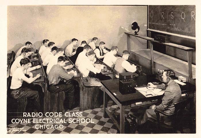
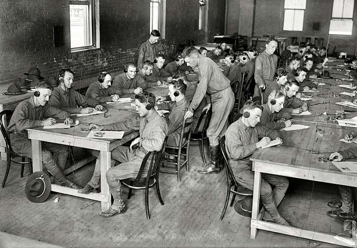
As wireless communications started, many of the US operators used American Morse. Some types of wireless detectors only worked relays and sounders, like coherer detectors. As wireless improved, it was obvious that International Morse was more suited for damped wave spark transmitters and for reception on mineral detector receivers. In 1912, the Wireless Conference in London ruled that all ship wireless messages were to be sent by International Morse. Most other wireless users also followed this rule. Hams still tended to use whatever they were accustomed to. Many hams at that time were also railroad telegraphers and American Morse was sometimes found on the hams bands. There was an attempt to make International Morse the standard for landline users but resistance from companies like Western Union and other wire companies, who knew that sending messages via American Morse was about 20% faster than International Morse (and also the wire companies didn't want to have to retrain their operators,) prevented International from being adapted for USA landlines. Eventually, as communications moved away from landline wire messages, American Morse wasn't used after the mid-twentieth century. International Morse has continued on being used in radio communications both for the military and the amateur.

Here's an example of the difficulty of learning and using American Morse. The letter T is a dash. The letter L is a long dash. The number 0 is an even longer dash. The letter P is five dots. The number 5 is three dashes. The number 6 is six dots. The letter C is a dot followed by a short space and then two dots.  The letter O is one dot, a long space and one more dot. The spaces can be three different lengths depending on the character or word or sentence. To become proficient in American Morse took a lot of time and a lot of practice. Receiving it is even more difficult. You can send International Morse and receive it fairly easily on a sounder (as was done almost everywhere except the USA by the 1880s.) Very late in the US railroad's use of telegraphic communications, some railroads did use International Morse but the majority stayed with "railroad code" until the end.  


Landline (Wire) Telegraph Equipment

The following is just a very small sample of the vast amount of Landline Telegraph Equipment that was produced. The earliest telegraph gear will be for wire landline use going back to as early as the middle of the nineteenth century. Most of what we find today dates from the early twentieth century. Landline used American Morse Code which was a significantly different code when compared to the later International Morse Code. Aurally the two codes are completely different with International operators hearing "dits and dahs" in sine wave tones while the American Morse operators hear "clicks and spaces between clicks" from a sounder. 

J.H. Bunnell Company, W.U. Tel. Co. & O.C. White Company

Sounder in Resonator Hood with Articulated "Straight-Arm" Desk Mount
 

The sounder is the "receiver" of the wire telegraph. Originally the "Morse Register" was a mechanical method of receiving the code but operators soon found that they could "read" the code directly from the aural information heard as the machine operated. This led to Morse's associate, Alfred Vail, building a device that allowed the operators to hear the code directly. The sounders were sometimes installed into resonator hoods to amplify the clicking sound produced. Sounders are rated by the DC resistance of the solenoids. The DC resistance determined the maximum distance between two stations where the sounders were connected directly to the line and were powered by the battery DC voltage source. The greater the distance between stations, the higher the DC resistance of the wire was and therefore the greater the voltage drop across the wire if the sounder solenoids were of a low DC resistance (to ground.) Sounders were produced from the mid-nineteenth century up into the 1960s or so.

Otis C. White was located in Worcester, Massachusetts and specialized in cast iron, articulated arm mounting devices, mainly for lighting for desks and machines. The use of the articulated arm allowed the operator to position the sounder resonator hood for best listening depending on the noise and activity in the station area. Active use is probably later than the patent date that is on White's arm, which is 1911. The actual use date of this one shown is probably in the 1920s or 30s. Obvious are the U.S. Army Signal Corps acceptance stamps implying the military use of this example.

The sounder used was built by Bunnell and has both solenoids wired to individual terminals. This allowed the user to connect the solenoids in series or parallel depending on the line distance. Each solenoid measures 200 DC ohms so a series connection results in 400 ohms and a parallel connection results in 100 ohms (although the tag indicates "18-400 ohms.") A metal Western Union (W.U. TEL. CO.) tag is mounted to the sounder base implying that WU may have been supplying the Army with their telegraph system in this particular case. The resonator hood is also built by Bunnell and it has a cast metal rear bracket that was probably for paper "messages to be sent."


- W - U - TEL - CO -

Western Union Telegraph Co.

Bunnell 120 Ohm Sounder and Algoma Resonator Hood
with O.C. White Co. Articulated "Curved-Arm" Mount


This is another version of Otis C. White's articulated arm mount for telegraph sounder and resonator hood. Note that with this version the main arm is curved downwards to reduce the total height of the assembly resulting in the hood being above the table top by less than 12 inches. Compare this "curved-arm" to the White articulated arm mount shown above which has the "straight-arm" version of the mount. With the "straight-arm" the total height of the assembly and hood is about 16 inches above the table. The "curved-arm" only has "patented" embossed along with "O.C.White-Worcester, Massachusetts" where the "straight-arm" has a 1911 patent date. This "curved-arm" version is probably the earlier of the two versions.

The Resonator Hood has "- W - U - TEL - CO -  RESONATOR HOOD  MFD. BY ALGOMA PANEL CO." on the tag.

The 120 ohm sounder was built by J. H. Bunnell & Co.

Probably dates from the early twentieth century.


Western Electric

3B Sounder in Resonator Hood with Brass Pedestal Desk Mount


Western Electric was the manufacturing arm of American Telephone and Telegraph Company. They made many types telegraph devices such as keys and sounders along with other telegraph equipment. Western Electric was the W.U. competition. Western Electric and Bell backed the telephone over the telegraph which seemed to favor W.U. at first. As the telegraph gave way to the telephone, W.U. lost substantially and they were eventually bought by the Bell System in the late twentieth century.

This is a Western Electric 3B 20 ohm Sounder mounted in an oak resonator hood mounted on an impressive brass pedestal.

DC Resistance versus actual distance has a few variables. The main voltage source was determined by how many batteries were being used. The potential available would be an important factor in distance covered. Although it's not really specified what voltages were used, it probably was between 50vdc and 150vdc. The size of the wire determined the DC resistance per foot of the line between the two stations. The distance between field poles determined what type of wire and what diameter wire was used and that determined the DC resistance per foot. Sounders and relays were normally energized and the entire line was normally a complete series circuit. Each key had a switch that was kept closed when all stations on the line were in the "receive" mode. To send, an operator would "open the key" and that would drop out the relays and sounders at which time the operator would begin sending his message and that operated all relays and sounders on the line. When finished, he would "close the key" to keep the circuit energized. Each station had its own main battery system (later DC generators were used.) All of the sounders (or relays) on the line presented a "series-parallel load" that was the DC resistance of the all of the solenoids connected in parallel at each station to earth ground but with the main line in series to each station added up. Each line had to have the total load calculated to keep the system capable of operating while taking into account all of the other variables that might happen along the line. The higher the total resistive load on the line, the lower the current flow on the line and the longer the distances that can be covered by the system but the higher potential required to operate the system. The reason for the "closed loop" powered system was that any trouble on a main line was immediately obvious and repairing those faults were easier to find with a "powered system."  


J.H. Bunnell Company

4 ohm Sounder

It's likely that several million sounders were built over the years from the mid-1800s up to the mid-1900s. Every railroad station had to have several. Sometimes the local telegraph office was at the local post office. Other times there was a specific "telegraph office" in the town. Then there were the many other users that included inter-office communications (pre-telephone) in large buildings or building complexes. These local users had the 4 ohm sounders. These were just about the lowest DC resistance available and allowed for very short distances on direct two-wire operation using a couple of dry cell batteries as the voltage source. Low resistance sounders were usually used on NO (normally open) circuits that wouldn't deplete the dry cell batteries as quickly. Some of the 4 ohm sounders were for instructional devices since this was about as "local" as one could get.

Patent date on this Bunnell sounder is May 7, 1895 but it probably dates from much later.


Signal Electric Manufacturing Company

20 ohm Sounder


Signal Electric Mfg. Co. started out in the 1890s as Menominee Electric Co. since they were located in Menominee, Michigan. The company built and sold telephone and telegraph equipment. The company also built some wireless items like loose couplers and other electrical parts. The name was changed to Signal Electric Manufacturing Company and they remained in business until the 1960s when they were purchased by a Thermos company.

This Signal Electric sounder is built a little different from the other sounders shown. Note that the individual pieces, the frame, the anvil and the solenoids are mounted directly to the wooden base rather than mounted to a metal plate that would then mount to the wooden base. The metal base mount provided a permanent alignment of the sounder components. Mounting the sounder components directly onto a wooden base could introduce misalignment if (over time) the wooden base warped or cracked. The 20 ohm DCR solenoids imply that the sounder was intended for relatively longer distances (or less load) when directly operated on the line or driven by a sensitive relay.  


Western Electric

3C 140 ohm Sounders


Western Electric 3C 140 ohm Sounders would be for long distance operation direct on the line. Initially, Morse's system used two wires but very soon it was discovered that a single wire could be run between stations and each station could use an Earth ground for the return. Each station had batteries for the potential and large surface area metal plates were buried to provide a substantial Earth ground. With low DCR sounders drawing more current (to ground) to operate the voltage drop across the single wire increased to the point where the sounder wouldn't operate. High resistance sounders didn't draw as much current and therefore could operate for greater distances before the voltage drop increased to the point where the sounder wouldn't function. The system depended on how many sounders were on the line. Since all of the sounders on a line at the station were connected parallel to earth, a greater number of sounders on the line would require each solenoid to have a higher DCR for less total load on the line.  

Most stations would use the low DCR sounders on a local circuit within the station and the main line(s) would be operating high DCR Telegraph Relays.


Landline Hand Keys

J.H. Bunnell 2A Legless Key for Western Union
Western Electric Leg Key for Western Union


Like sounders, millions of hand keys have been built by many different manufacturers since the wire telegraph service began. The "landline" hand key is slightly different from a "radio" key. The "landline" key must have a lever switch since that allowed the operator to "open the line" in order to send his message using the hand key. Each closure of the hand key lever would operate all of the sounders on that line. When the operator was finished he "closed the line" which meant that the switch lever was closed which then completed the line circuit and returned the station and the line back to "receive." Many wire telegraph keys were later stripped of their lever switches by ham radio operators since the switch wasn't necessary for radio operation. Wire telegraph keys also had very small contacts, usually .060" diameter was the normal size. Some keys were fitted with long connection rods that protruded though the table top and allowed for wires to be routed under the table. These types were called "Leg Keys." Most keys were "legless" and mounted directly on the operator's desk and were wired as needed. Two examples are shown, the Bunnell 2A Legless Key was made for Western Union and is marked as such. The second key is a Western Electric Leg Key built for Western Union. Both keys date from around 1900.


J.H. Bunnell Co.

Key on Board (KOB) Learner's Set


These wooden board key and sounder sets (called KOB, Key On Board, though they probably should have been called KASOB, Key And Sounder On Board) were popular mainly as a learning tool. Very early uses sometimes had interconnected KOBs as methods of local pre-telephone communication within large buildings or other similar applications (even large houses.) Rarely, a KOB might have been used on the line in a station but normally the station setups had the key mounted to the table and the sounder located in a resonator box with these two devices working into telegraph relays for long distance communication over the wires.

Shown is an early Bunnell KOB from the early 1880s. It features a "camel back" key with the steel lever painted gold. The key's base is also gold finish. The sounder has the earlier style of a cast iron coil and sounder arm frame and a separately mounted brass anvil. The KOBs made in the nineteenth century tend to have very decorative pin striping and scrolling typical of the era they are from. A patent date is stamped into the wooden base of May 1, 1877. Also, the wooden base was modified by removing the front one inch of material to allow mounting it directly to something or for some custom installation.


J.H. Bunnell Co.

Key on Board (KOB) Learner's Set


This Bunnell KOB is a somewhat later than the set shown above. It probably dates from the late-1880s. Its key has the "camel back" lever design but this lever is made out of brass. Normally, the sounder's solenoid coils were covered with an embossed type of paper that was usually black in color. The paper covers are gone showing just the cotton covered magnet wire used in winding the solenoids. Note that the key knob and the switch knob are brown in color. At the time, condensite or hard rubber was used for these pieces. Hard rubber tends to turn brownish-green with long exposure to light. Again, as typical for the era, decorative pin stripping is applied to the black japan finished key base and the sounder arm/solenoid coil frame of the sounder.


Unknown Manufacturer

Key on Board (KOB) Learner's Set

There are no markings to indicate who manufactured this KOB set. The thumb screw knurls look like Bunnell's style but that's not a positive indicator since the connection terminals are very different from those used by Bunnell. This KOB set probably dates from the 1890s. It has a later style key mounted on the board. Note that this key has the stamped steel, single-piece, nickel-plated lever with the gentle downward curve for proper placement of the knob. This style of lever was developed by Bunnell in the 1880s with the purpose of simplifying construction and eliminating the problem of loosening of the pressed-fit lever pin. The sounder is still comprised of separate pieces mounted directly to the board indicating that the KOB is not so late that it would have a base-mounted sounder. This sounder's solenoids are 4 ohm indicating that it's intended for local operation, as would be typical of a learner's set. The "4 OHMS" is stamped on the board. Usually, when used as a Learner's Set with 4 ohm solenoids, the terminals would be connected to two dry cells or about 3vdc which would be sufficient to operate the sounder. Two Learner's Sets could be connected with the dry cells in series.


Unknown Manufacturer

Telegraph Relay


When great distances had to be covered, sounders generally weren't operated directly on the line. A sensitive relay used high DC resistance solenoids to operate a set of contacts that could operate a local circuit which had lower DC resistance sounders. The DC resistance on this relay is 50 ohms which allowed it to operate greater distances between stations. There is an extra switch circuit to the right for opening or closing the wire circuit. The switch contacts go directly to the two terminals on the right end of the relay. Lifting the red knob opens the switch for sending. The middle terminals are for the local line connection and the left end terminals are for the wire line input was normally wired to include the switch circuit to keep the line closed for receiving messages.

The manufacturer of this beautiful device is unknown. There isn't any builder identification anywhere. This relay probably dates from the early twentieth century.


Unknown Manufacturer

Polar Relay


The builder of this beautiful Polar Relay isn't identified. The two solenoids work in conjunction with the "wrap-around" horseshoe magnet. The contact arm remains stationary between the N and S contacts if the solenoids aren't energized. If a connection is made to the two input contacts that is positive then the arm will move to the N contact. If the opposite polarity is made to the input contacts (negative) then the arm will move to the S contact. The connection labels are arbitrary and dependent on the hook up and system. The basic function is that the change in polarity between the two input contacts results in the selection of either arm to N or arm to S with those terminals being the three grouped together on the left side of the board. The input terminals are the two grouped on the right side of the board. The polar relay worked with a different type of telegraph system called the duplex circuit that could run multiple signals on a single wire. This evolved into the quadruplex system the used polarity changes for additional signals on a single wire. This polar relay is beautifully made with turned finished brass sub-base and a mahogany wooden base. It probably dates from around 1900, perhaps a little earlier (it came from Virginia City, NV.)


The Instructograph Company, Chicago, Illinois

American Morse Instructograph


This is an early Instructograph with wind-up motor drive. Note that this version has a removable lid that is held on with two latches. Note also that the tapes are for American Morse. I'm not sure about the masonite panel. It appears to have wear and looks original but I've never seen masonite used as a panel on any other Instructograph. Note that this version doesn't have a knob anywhere on the panel. This indicates that the machine has no internal, battery operated audio oscillator. This implies that the machine relies on the user to provide an external indicating device. Since the tapes are for American Morse the reproducer should be a sounder and battery combination.


U.S. Army Signal Corps

Contractor: The Allen D. Cardwell Mfg. Corp.

Model: TG-5-A Telegraph Set


Telegraph Sets were used for various types of communication where wires had been placed between the points that were sending and receiving. The distance covered depended on the voltage used, condition of the wires and, if an earth return was used, then the ground conductivity was important. Internally, a three volt DC battery source can be used. Also, the three volts can be connected externally, if necessary. If the bell is to operate then 22vdc is necessary and that has to be connected externally. The buzzer operates on three volts but, depending on the condition of the wires and the distance, it was sometimes necessary to adjust the "Spring" and the "Gap" of the buzzer for best results. The single earphone was for listening to the buzzer. The bell would operate if the earphone wasn't inserted into the jack.

Once everything was connected, the sender would depress the key several times. This would ring the bell at the other end of the line. The receiving operator would insert his earphone and could then hear the buzzer operating as the sender depressed the key. The line is closed when the key is up so when the sender stopped then the receiving operator could send. Wires were connected to L1 and L2. A single wire could be used "L1 to L1" with L2 grounded at both stations. Multiple stations could also be set up in both series connections or with common earth returns.

These Telegraph Sets were intended to be temporary communications or somewhat portable considering that the wires did have to be run first. However, the original package also included a canvas carrying bag for the TG-5-A. The implication is that using the TG-5-A assured the communications were somewhat secure since the operators had to be Morse proficient. And, since the reproducer is a buzzer, International Morse is implied.

Contract date on this TG-5-A is 1941.


                               CONTINUE TO PART TWO                                Return to Home Index


Radio Boulevard
Western Historic Radio Museum

 Vintage Radio Communication Equipment Rebuilding & Restoration Articles,

 Vintage Radio History and WHRM Radio Photo Galleries

1909 - 1969

- 60 years of Radio Technology -


This website created and maintained by: Henry Rogers - Radio Boulevard, Western Historic Radio Museum © 1997/2023