Radio Boulevard
Western Historic Radio Museum
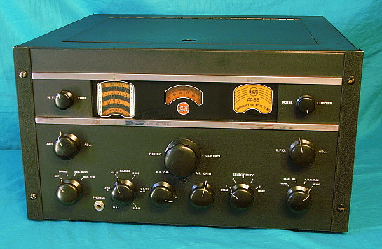
RCA's Amazing AR-88 Series of Receivers
Part 3
Sweep
IF Alignment
RF Tracking Alignment
Typical AR-88D Rebuild
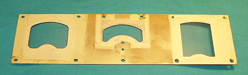
photo left: AR-88D Restoration Project - Hey! Where's the gearbox?
|
Radio Boulevard
RCA's Amazing AR-88 Series of Receivers Part 3 Sweep
IF Alignment
photo left: AR-88D Restoration Project - Hey! Where's the gearbox? |
|
|
Sweep IF Alignment of the AR-88 Receivers |
| Why bother doing a sweep alignment? A lot of users don't have the proper equipment. It's time consuming. Why bother? Well, if you are going to use your AR-88 series receiver for CW or SSB only, then maybe a standard alignment is all that you'll need. However, if you want a very smooth response while tuning through those broad AM signals with no changes in the amplitude as you tune from one side of the signal to the other, in other words - no "peaks and dips" - then you are going to have to perform a sweep alignment on the IF section of your AR-88 series receiver. Here's how it's done... |
|
Preliminary Alignment - The AR-88 uses a stagger-tuned IF system when in Selectivity POS. 1 and POS. 2 with two under-coupled IF transformers and two over-coupled IF transformers. This requires a sweep generator for proper symmetrical alignment. A complete description of the procedure is below, including actual photographs of the oscilloscope patterns taken during an actual sweep alignment of an AR-88D. However, before you do any sweep aligning, you need to center the entire IF section at the proper frequency, which is dependent on the crystal filter's crystal frequency. Before doing any adjustments on the IF or the RF, it might be a good idea, especially if the receiver is one that was stored in less than ideal conditions, to put a drop of thin oil on all of the threads on all of the adjustment shafts. Just a drop will do and let it soak over night before proceeding with the alignment. Input an IF signal to the Mixer grid and peak all of the IF transformers - remember you're going to sweep align this later so just peak them for now. Proceed on to the RF tracking adjustment per the appropriate manual. When this is completed, you can go on the the sweep alignment of the IF. The manual's instructions for sweep alignment are vague and assume you've performed sweep alignments many times before. Only drawings of the oscilloscope patterns are provided with some very basic directions (and these are only in the later manuals.) The following is a more detailed set of instructions that assume you've done alignments before but maybe not sweep alignments. I also assume that you are familiar with the operation of the test equipment described. Be sure to thoroughly read the later RCA sweep alignment instructions and use them along with my instructions. The RCA instructions specifically call out the component designations for adjustment for positive identification where I just refer to the function of the connection or adjustment, e.g., 4th IF transformer or 3rd IF amplifier grid, etc. Sweep Alignment - Sweep Alignments of a receiver's IF section will require a signal generator that is capable of a frequency "sweep" function. Back in the forties, it was common to find a "Wobulator" or mechanical FM signal generator. These devices used a motor to turn a variable capacitor that was in the signal generator's oscillator circuit. The effect was to rapidly change the set frequency at a rate determined by the speed of the motor. The frequency deviation, or by how much the frequency changed from a "set frequency," was based on the variable capacitor's maximum and minimum capacitance. Most of the motors ran at 1728 RPM which is about 28 Hz and this is an ideal sweep rate for alignments. Today, we generally use a modern Function Generator that has an electronic frequency sweep function built-in. There are many Function Generators available that were at one time "laboratory equipment" that are now on the "used market" and very reasonably priced. These will work fine for sweep alignments. Be sure that the sweep rate is adjustable and that a "ramp output" (or "modulation out" that is specific to the sweep rate) is provided. Also, be sure that the Function Generator will produce sine waveforms up to at least 1.0MC - most do. I use a Hewlett-Packard 3312A Function Generator for my sweep alignments. The oscilloscope is a Tektronix 475. The easiest type of Oscilloscope to use in a sweep alignment is a two-channel 'scope that can be set-up to an "X-Y" configuration. Most modern 'scopes have this function. Look at the Time Base control and usually just past the slowest sweep is "X-Y." This allows you to look at the receiver's IF output on the basis of just one sweep at a time determined by the "sweep ramp output" of the generator. It results in a very stable pattern that shows the IF passband characteristics. When the old "Wobulators" were used with 'scopes the sweep ramp from the Wobulator had to be fed directly into the Horizontal input of the 'scope to generate the "sweep" pattern. Stability was always an issue due to the mechanical nature of the signal. Modern gear is much better. The "Y" input to the 'scope is connected to the output of the second detector at terminal C of the fourth IF transformer and is left there - you don't have to move it. The "X" input to the 'scope is connected to the Ramp (Mod.) Output from the Sweep Generator - again, it stays put. This provides a "one sweep" look at the IF passband that is monitored by the "Y" input but since the sweep generator provides a continuous ramping sweep of about 25hz, the IF pattern appears to be stable and continuous. Your signal input to the receiver comes from the signal generator's P-P Amplitude Output which is the waveform that is amplitude adjustable and has its frequency sweeping. You may find that you have to "invert" the input of the Y channel because the output of the AR-88 detector is negative. You will have an "upside-down" or "U" shaped pattern unless your 'scope channels have the ability to invert the signal input. Always use real oscilloscope probes since they don't load down the circuit. The connection from the Function Generator Ramp Output to the "X" channel of the 'scope can be a coaxial cable with BNC fittings. Any loading or radiation pickup on unshielded cables will affect the 'scope patterns. The alignment process depends upon always to be looking with the 'scope at the 4th IF transformer (detector output,) terminal C and then work your way forward through the IF section by first injecting a sweep signal at the grids of the 3rd IF amp, then on to the 2nd IF amp, then on to the 1st IF amp, until you are finally injecting the sweep signal at the grid of the Mixer stage. You will then be viewing the sweep signal passing through the entire IF section of the receiver. This allows you to see the actual characteristics of the IF passband, including its shape and bandwidth. >>> |
>>> Unfortunately, there is no specific set up for amplitude,
frequency deviation, X-Y gain settings or generator starting frequency
that is "correct" since every receiver is somewhat different and many of
the settings will interact. Some of the settings will be individual
preference. So the best thing to do is to connect up the test equipment
as described and experiment with what gives the best image. Be sure to
keep the sweep rate low at around 25Hz or less - this is important for
good stability and an accurate image of the IF passband. Also, keep the
generator amplitude as low as possible that still gives a good
representative image of the IF passband. Once you have experimented
around with the set-up, you'll notice that the start frequency is not
very critical as long as the frequency deviation is adequate to cover
the IF passband. Usually 20Khz to 25Khz deviation gives a good image.
The IF for the '88 series is 455kc while the '91s and AR-88LF use 735kc
for the IF. You will set the sweep generator starting frequency a bit
lower
these IF frequencies depending on the receiver type.
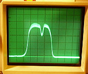
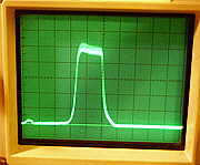
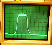
Be sure to couple the sweep generator signal to the various grid inputs of the receiver through a .01uf capacitor. Most modern generators are very low Z, usually around 50 ohms, so the capacitor will help prevent loading of the grid. Now, we are assuming that you have already aligned the receiver to its center IF with reference to the crystal filter's crystal frequency. Connect the 'scope "Y" input to terminal "C" on the fourth IF transformer. Now, start with the 4th IF transformer and inject the sweep generator signal to the grid input of the 3rd IF amplifier tube. Adjust the 4th IF transformer for a symmetrical pattern but be sure that the amplitude of that pattern remains at the same level. This IF transformer is not switched so the position of the SELECTIVITY control has no effect. See photos and drawings below. Next, leaving the "Y" input connected to terminal C, inject a sweep signal to the grid of the 2nd IF amplifier tube. This brings in the 3rd IF transformers which are over-coupled in "BROAD" POS. 1 and normally coupled in POS.2. You have to switch between POS. 1 and 2 and adjust the IF transformers for the very slightly "dipped" pattern for 1 and a normal slightly "rounded" peak for 2. Symmetry is most important here. In performing all of these adjustments be sure to try to keep the IF amplitude unchanged, otherwise you are detuning the IF. Only very small changes are required to achieve the correct patterns. NOTE: The British AR-88 manuals specify only adjusting the bottom IF adjustments. The RCA manuals aren't specific. I have found that you have to adjust both the top and bottom slugs of each IF transformer to achieve the best patterns. Next, inject the sweep signal to the grid of the 1st IF amplifier tube. Now, you'll be seeing the combined 2nd, 3rd and 4th IF transformers. You may have to adjust the sweep generator amplitude a bit for a good 'scope pattern. Adjust the 2nd IF transformers for a significantly "dipped" pattern in POS. 1 and a narrow-flat pattern in POS. 2. Again, try to keep the patterns symmetrical and the amplitude unchanged. Move the sweep signal to the Mixer grid. At this point you will have to increase the sweep generator amplitude for a good pattern on the 'scope. Then adjust the first IF transformer for a broad flat pattern in POS.1 and and narrower but somewhat flat pattern in POS.2. See photos and drawings below. Only one IF transformer is used for the 4th and the 1st IF transformers. Two IF transformers are used for both the 3rd and 2nd IF transformers. While doing all of the manipulations to the pattern, be sure to try and keep the amplitude of the waveform unchanged. Detuning just to achieve the pattern will detune the IF resulting in reduced gain. Try to keep the patterns as symmetrical as possible. This is a time consuming process and only minute adjustments are required. IMPORTANT NOTE: Don't expect the patterns that you see on the 'scope to look exactly like the drawings. See the photographs below of the actual patterns from an AR-88D alignment for an idea of what you might really see. You won't be using the same type of equipment that RCA used back in the 1940s when they made the drawings. Also, maybe when the receivers were new it was possible to get the exact patterns but, after 75+ years, the components and the IF transformers have aged enough that just getting close is about the best that can be achieved. Try to adjust for the closest appearance to the drawings with good symmetry, fairly flat tops and no loss or very little loss in amplitude. Also, remember - this is a time consuming process that requires only minute adjustments of the IF transformers. Don't expect the adjustments to easily "fall into place" - they don't. Take your time and only make small adjustments. After the 1st IF transformer is adjusted all that remains is to adjust the crystal filter section. Selecting POS 3, 4 or 5 will operate the Crystal Filter. The object of this alignment is to maintain a symmetrical pattern while progressively narrowing the bandwidth. This is very easy to accomplish with the RCA instructions and adjusting the Crystal Load L-34 and the trimmer capacitors provided. |
|
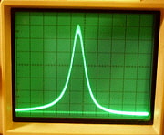
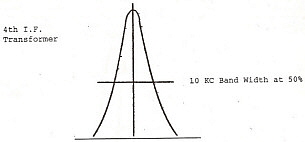
4th IF Transformer Only The oscilloscope pattern to the right shows the actual pattern on a rebuilt AR-88D receiver. Compare this to the drawing from the manual shown and you'll note that the actual pattern is very similar although a bit sharper at the peak. This scope pattern could be broadened out with the oscilloscope controls but it is only necessary to obtain a symmetrical pattern at this point. |
 |
|
Equipment
Used HP - 3312A Function Generator Tektronix - 475 Oscilloscope |
|
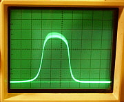
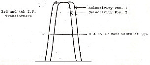
3rd & 4th IF Transformers Actual patterns shown to the right with POS 2 on the left and POS 1 on the right. The 'scope patterns are similar to the drawing although the patterns are overlaid in the drawings and we are showing individual photos. The 'scope patterns are a little more rounded on top. Note the width difference. We are trying for the best symmetry of both patterns without loosing gain. |
 |
2
|
1
|
|
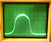
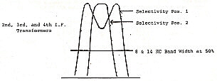
2nd, 3rd & 4th IF Transformers Actual 'scope patterns shown to the right with POS 2 on the left and POS 1 on the right. The patterns are similar to the drawings although the dip in the POS 1 pattern is not centered and is a little bit sharper. POS 2 is a nice flat pattern, though rising slightly to the left. Note the width difference between POS 1 and POS 2. |
 |
2
|
1
|
|
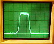
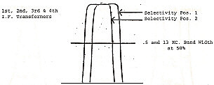
All IF Transformers Actual patterns shown to the right with POS 2 on the left and POS 1 on the right. The patterns are still similar to the drawings although POS 2 has a bit of a rise to the top of the pattern increasing to the left. POS 1 looks symmetrical and should provide good fidelity. Note the width different of the patterns. This AR-88D sounds great and one hears no "gain peaks" while tuning through a broad AM signal. |
 |
2
|
1
|
| RF Tracking
Alignment - This alignment will require some special
tools. RCA did supply some with the receiver and they were usually
installed in the mounting clips on the tuning condenser cover. Nearly
all of the original tools are always missing today but you can utilize
standard tools instead.
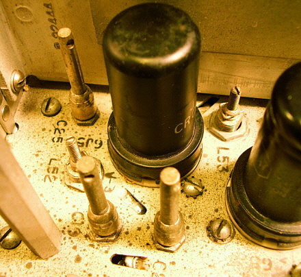
Note in the photo to the right that the capacitive adjustments are long "plunger" shafts with a hole at the top. Also, note that there is a "locking" collar at the bottom of the capacitive shaft. These "locking" collars require a 5/16" wrench to loosen. I find that a very deep 5/16" socket (1/4" drive is what I use) works pretty well but a 5/16" open-end wrench would probably also do the job. These capacitive shafts can slide up and down once the collar is loosened and this is how the capacitance is adjusted. It's probably a good idea to spray a small amount of De-Oxit on the shafts before beginning the alignment. This will help with the common sticking that's encountered and will provide a good chassis contact for the "plunger" shaft. The hole in the top of the "plunger" shaft allowed a tool to be inserted that provided an easy way to move the shaft up or down. I just use an Allen wrench that fits the hole and use that to move the shaft to the correct setting. After the proper capacitance is set then the "locking" collar can be tightened. Monitor your output and be sure that tightening the locking collar doesn't change the adjustment. The inductance adjustments are much easier to deal with only requiring a small blade screwdriver for setting. One thing that is awkward is the inductance adjustments for the 1st RF amplifiers which requires accessing the adjustments through holes on the rear chassis apron. The SC-88 is different and has all adjustments on top of the chassis. A 200pf capacitive load on the BC band and a 200 non-inductive resistance ohm load on the other bands will be required for signal input loads. I use a Weston Audio Output Meter connected to the 600 ohm output as an indicator for the receiver's maximum output. I have the RF signal generator in the modulated mode with a 400 hz tone and the receiver in MAN (AVC off.) Always keep the RF signal generator at the lowest levels of output that provides enough signal for the Weston to show an indication using its lowest scale. You can also adjust the receiver output level with the RF Gain control and the AF Gain control. The idea is to use the lowest input signal that gives a good response in the receiver and a good indication on the lowest scale of the Weston Audio Output meter. With the SC-88, the capacitive trimmers are changed to a more standard trimmer type of adjustment that is adjusted using a small blade screwdriver. |
|
|
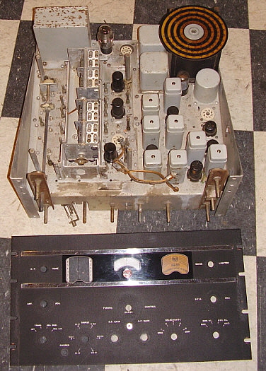
A Typical AR-88 Rebuild |
| The AR-88 receiver shown to the right was a donation from a fellow
ham. He had sent the receiver off to be rebuilt by an out-of-state
"restorer" but, after a couple of years, the AR-88 was returned minus
several critical parts. Frustrated with the whole project, the ham gave
me the incomplete receiver to see if something could be done to keep the
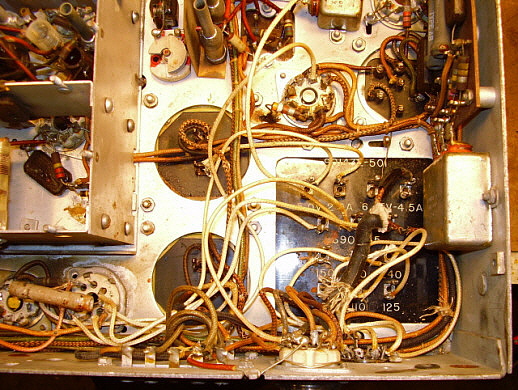
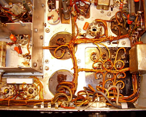
AR-88 from becoming just another "parts set" awaiting oblivion. Inspection - Obviously missing was the main tuning gear box. Without this crucial part, the receiver was not going to do much of anything. Along with the gear box, the logging dial was missing. All of the knobs were also missing. On the underside, the AC voltage selector switch was smashed. Several wires had been added and several other wires removed. Of course, the shields were gone too. The rectangular plastic dial cover had some wear on the inside that affected the band indicators. On the plus side, this receiver had an incredibly nice front panel - it was just beautiful. Also, just a little corrosion was evident on the chassis. These great "pluses" were really the inspiration for trying to put this AR-88 back together. Parts Procurement - Luckily, I made contact with VE8NSD in the Northwest Territories of Canada who is an avid AR-88 collector. He buys them at Canadian government auctions where the receivers are notorious for poor condition and incompleteness. Garth was able to supply nearly all of the missing parts for this AR-88. Shields were one exception. The sheet metal parts seem to vanish never to be found again. Also, if one is looking for a Carrier Level meter, it is another part that is beyond difficult to find. This was because only one in a thousand AR-88s was ever equipped with a CL meter. More Issues and Conflicting Parts - After a thorough inspection I discovered that this receiver chassis was actually an AR-88F "diversity receiver" that had been partially modified into an AR-88D by removing the DIVERSITY IF GAIN control potentiometer and wiring. Then a very nice panel from an AR-88D was added to the package. It was decided that since this AR-88 was incomplete and wasn't ever going to be a great original example I might as well do a full rebuild on the receiver to see what kind of improvement that would result in when compared to the three nice original receivers I have (CR-91, CR-88A and SC-88.) What was apparent when looking underneath the chassis was that the former rework was poorly done. It appeared that new wiring was put in place for the rectifier socket replacement. The rework was very sloppy and had to be removed. There were some other problems caused by careless rework, mostly in the form of damaged wire insulation. The AF Gain control had been replaced with a short shaft potentiometer so the rebuilder soldered a 1/4x20 threaded shaft to the end of the short shaft - ultra crude, to say the least. |
|
| Required Component
Replacement - A closer check of the resistors showed that
many of the IRC type resistors were out of tolerance by a significant
amount, usually in excess of 100%. For the resistors that needed
replacement I used standard JAN type 1/2W carbon resistors. In looking
at the original IRC resistors, which look like 1W units, one would think
the 1/2W resistors would be too small but the later versions of the
AR-88 use standard JAN 1/2W resistors throughout the receiver. I looked
through several boxes of carbon resistors and found NOS replacements for
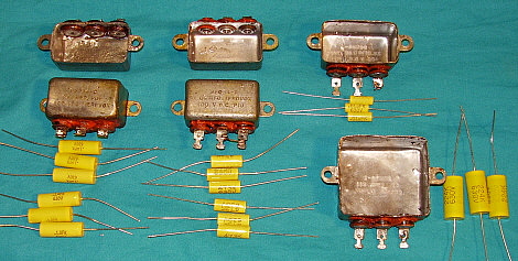
all the needed resistors. COMPONENT QUALITY - IMPORTANT NOTE: International Resistance Corporation resistors that were manufactured during WWII (and somewhat later) seem to be plagued with a "carbon drift" problem. Almost all IRC resistors of that period will not be at their original manufactured resistance. It isn't predictable which values will drift or by how much the resistance will change. The only solution is to physically check each resistor for its present resistance value and replace any resistors that are more than 20% out of tolerance. This IRC resistance drift problem is found in every type of WWII electronic gear that used IRC resistors, not just the RCA gear. I decided to replace all of the Micamold and metal tub capacitors. I chose SBE orange drops to replace the .0047uf, .0033uf and the .0022uf Micamold capacitors (these are listed in the parts list in picofarads, so 4700pf = .0047uf.) Most of the Micamold capacitors were "bulging" at the center - that couldn't be good. The bulging center indicates excessive heat generated by high leakage current. It's possible that the Micamold's with excessive leakage may have caused the A-B resistor drift depending on the particular use of the capacitor-resistor connections in the circuit. COMPONENT QUALITY - IMPORTANT NOTE: Micamold capacitors are not "mica caps." They are molded paper-wax caps - an earlier version of the infamous Sprague "Black Beauty" molded capacitors. Micamolds have the same problems (maybe worse) as the typical Black Beauties with excessive leakage current. If you examine the Micamold capacitors carefully you will almost always see that the center of the capacitor body is bulging due to excessive leakage current causing heat buildup and the resulting swelling or bulge. All the Micamolds must be replaced for reliability and top performance. |
| Tub Capacitor
Rebuilding - The metal tub capacitors all had red
silicone rubber applied around the terminals. The red rubber is inside
the can so it must be original to manufacture. Though it looked crudely
applied it seemed to deter oil seepage since there was no evidence of
any leakage. I removed one of the tubs to see if they had actually been
rebuilt but the bottoms were still in place indicating they had not. For
the tub capacitors, I chose the "yellow jacket" polyester type
capacitors since they fit into the metal tubs better.
There are six triple capacitor metal tub mount units used in the AR-88. These were removed and using a large old-style soldering iron, the bottoms removed - details (and a PCB oil warning) about the procedure is above in Restoration Suggestions in Part 2 of this article (also an update on using a Dremel Tool and cut-off wheel instead of the large soldering iron - much faster and a lot cleaner.) I chose to install the polyester film type of capacitors because they fit into the metal tubs and are excellent replacement capacitors. I don't put the bottom back on the tub for two reasons - first, it's not necessary since the tub is mounted up against the chassis and second, removal of the bottom ends up destroying the bottom cover anyway. |
|
| Wiring and Rectifier Socket
- Another problem was the replacement tube socket for the rectifier
tube. Although someone in the past had installed a ceramic socket, it
was made by National and the mounting holes didn't line up. Fortunately,
no extra holes were drilled but the socket was just mounted with one
screw instead. Finding the correct ceramic socket might have been
difficult except that I remembered I had a parts chassis from the IF/AF
section of an old RBB receiver. These WWII receivers were built by RCA
and they used the exact type of ceramic socket needed for the AR-88. The sloppy wiring that had been installed in the receiver ended up removing much of the cable harness lacing. I replaced most these wires because they were too short for proper routing and then I had to replace the missing cable lacing. I used waxed string that I laced around the wiring harness with a "needle" made out of 20 gauge wire. The needle allows easy threading around the harness without too much lifting of the harness. After all of the work was completed to the wiring, amber shellac was applied to the harness to hold everything together better and to impart an aged look to the wiring. |
|
|
|
|
AC Power Switch, and the RCA "Meatball" - Since the AC voltage selector switch was broken and a good condition replacement couldn't be located, I soldered the "arm" wire to the 125vac terminal on the switch body which accomplishes what the switch would do if set on 125vac. A vintage two-conductor power cord was installed with vintage plug. Since I always operate these receivers in the ham station, the chassis is always grounded via the station ground. Therefore a non-original three-conductor power cord with grounded plug becomes redundant. I installed a modern replacement 2 meg potentiometer (linear) for the AF gain control. The replacement was a high quality unit but the shaft was very short. I used a metal .25" sleeve coupler to add the proper shaft length. The RCA "meatball" emblem was pretty rusty. It was restored as described above in "Cosmetic Restoration" with excellent results. Plastic Panel Problems - The plastic panel that covers the dials looked to be in excellent condition but someone in the past decided the back was too dirty. Unfortunately, the dirt was lacquer based and apparently the panel was scrubbed intensely with Windex or some other kind of harsh cleaner. Of course the lacquer based dirt wasn't removed but some of the white paint transfer parts of the dial cover were affected. Restoration required first to not worry about the dirt on the back of the panel. Then, luckily only the white was affected by the solvent and the black transfers were still in fine shape. This only required that the white be reapplied. I mixed a matching color with Artist's Acrylic, masked off the area so I would get a very straight edge. I thinned the paint quite a bit so several coats were required with time between coats for drying. >>> |
|
| Power up -
Problems are always to be expected when a project of this complexity is
involved - that is, major parts missing, non-original wiring and with
some disassembly of the unit. So, we weren't too surprised when, upon
power-up, all this AR-88 did was to produce a low frequency "growl."
Pulling a couple of tubes isolated the problem to the 1st AF amplifier
section and the problem was caused by a misplacement of the 1 meg
resistor in the grid bias divider. This resistor is located on the
component board and all that was necessary was to move one end of the
resistor to the adjacent terminal to have the proper connection. This
stopped the low frequency oscillation but still no signals. A quick
check of the IF section revealed that there was no screen voltage on the
3rd IF amplifier tube. This was traced to a mis-wire that involved the
screen bypass capacitor, a multiple cap tub mounted on the chassis
inside wall, not having the screen voltage wired to the correct
capacitor terminal and therefore not connecting to the 1K screen load
resistor. The correction required swapping the connections to the
outside terminals on the three terminal tub. This time the receiver
sprang to life upon power up. A quick check showed that all bands were
functional and all controls seemed to function correctly. I performed a
"quickie" IF alignment (not a sweep alignment) to see how far off the IF
was. It was very close. A run through the AM BC band showed that the
audio was everything I was expecting. On shortwave, there were some 40M
and 20M hams operating on SSB and CW that were received. Also, Radio
Venezuela was tuned in and luckily they were broadcasting music -
incredible audio. I let the AR-88 operate for about five hours and
checked the power transformer and the chokes for temperature - all three
were just barely warm. The "power up" test resulted in everything electronic functioning correctly on the AR-88D. When the alignment of the receiver was started it became apparent that we weren't going to be able to complete the RF Tracking part of the alignment due to gear box problems that prevented accurate dial readout. |
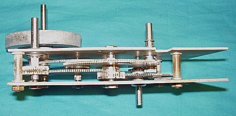
| Gear Box Problems
- The gearbox was obtained from VE8NSD from one of his parts sets. I
cleaned and lubricated this box as described in the Electro-mechanical
Restoration section above. The gear box looked great but a problem
surfaced when the gearbox was mounted to the chassis, coupled to the
tuning condenser and the main tuning dial mounted to the shaft. Though
the tuning condenser rotation was fine the main tuning dial would move,
then stop, then jump ahead. The problem was caused by severe wear in the
dual spring-loaded 270º gear that drives the main tuning dial from a
gear mounted on the tuning condenser drive gear. In fact about half of
the gear teeth were broken off the brass gear that drives the dial. This
problem was mostly likely the result of one of the original military
operators "spinning" the dial until it "slammed" against the mechanical
stop which happens to be on the split-gear that drives the
dial/condenser gear. The mechanical stop-tab was severely bent showing
that the gear had "slammed into" the stop several times with
considerable force. I exchanged the first gear box for another one from
Garth. This one was in excellent overall condition but when installed,
it also "jumped" at the top of its range. This time the problem was due
to only one tooth being missing from the dual 270º split-gear.
It seemed likely that since all of Garth's CR-91A "parts sets" had been acquired from surplus sources they probably all had similar mechanical issues and that was why they were sold off by the Canadian government as surplus in the first place. All of the other CR-91A parts purchased from Garth were in excellent condition. Garth provides a great service for the AR-88 series restorers. It just seemed that the receiver gear boxes had suffered at the hands of the former military users. See section above "Tuning Gear Box Variations" for more details on the gear boxes. |
|
| A Third Gear Box is Found
- In August 2011, I received a telephone call from Don Trueman VE4AY in
Winnepeg, Manitoba. Don said that he had an "unused" (maybe "NOS") AR-88
gear box that he would donate to this restoration project. He indicated
that the AR-88 Gear Box had been setting on his parts shelf for the past
15 years and that he was glad his AR-88 "spares" was finally going to be
installed into a receiver. When the gear box arrived I examined it
carefully and was surprised to find that the dial drive split-gear was
quite different from gears in the surplus CR-91A gear boxes. A quick
examination of my AR-88 series receivers showed that they all had
split-gears just like the one in the gear box I had just received from
Don. My conclusion is that probably only CR-91A receivers have this 270º
split-gear that has been such a problem. So, not only did I get a nice
condition, working gear box from VE4AY but I also learned why the former
replacements had been so problematic. I cleaned the new AR-88 gear box with a WD-40 flush and brush. I then repacked the shaft bearings using the old style "stringy" sodium-based grease. This grease is similar to the original grease used in the 1940s and has a higher viscosity than modern "red" grease. This "stringy" grease has much better damping qualities, that is, the ability to reduce clearances in the gear teeth for a smoother mesh and operation. After mounting and connecting the coupler, the new gear box performed perfectly. Another Part Surfaces - I was able to trade some medium size RCA knobs for a nice condition tuning condenser cover. Though the RF cover is still missing, having the tuning condenser cover is important as it provides protection to the tuning condenser and slightly alters the RF tracking, though not enough to affect alignment significantly. |
Sweep IF
Alignment - The IF alignment was performed as described
in the section "Sweep IF Alignment of AR-88 Series Receivers"
above. No problems were encountered. In fact, the photographs that
illustrate the various IF patterns as seen on an oscilloscope were taken
while sweep aligning this AR-88 receiver. What is noted with a sweep IF
alignment is the absence of "peaks and dips" in the signal level when
tuning through very broad AM signals. RF Tracking - Fortunately, the arrival of the NOS gearbox and the tuning condenser cover all happened before I actually performed the RF Tracking alignment. This of course meant that I only had to do the RF Tracking alignment one time. I performed the alignment as described in the above section: "RF Tracking Alignment." Tube Problem - Although all of the tubes were tested and replaced as necessary, tube testers do not find all tube problems. A microphonic tube is one type of problem that tube testers can't find (they actually can but few of us want to hook up headphones and tap the tube under test - besides only a few types of tube testers have the capability to test for "noise" - mostly military types,...like the popular TV-7.) That was the case with the 6SJ7 First Audio Amplifier tube. Unusual noises, especially "ringing" when tuning or operating the Audio Gain were the symptoms. Tapping on the side of the tubes when the receiver was operating narrowed the suspects to the 6SJ7. A known good 6SJ7 from another operating '88 receiver confirmed that the suspect 6SJ7 was microphonic. Another 6SJ7 was installed and that cleared up the problem and allowed the receiver to operate correctly with great audio and plenty of gain. Dials - Looking at the photograph below of the finished receiver, it's apparent that the main tuning dial is one shade of yellow, the logging dial is another, darker shade of yellow and the ID plate is another, lighter shade of yellow. All of this happened because of the missing logging dial and the fact that the panel wasn't ever the original one for the chassis. At any rate, it's probably not that important and isn't too noticeable when the receiver is turned on and the dial lamps illuminate. |
| Conclusion -
Is it worth all of the work to fully rebuild an AR-88? If you want an
example of the AR-88 series that is functioning like it did when it was
new, that you can leave turned on for hours and that sounds incredible,
then the answer is, yes! What is apparent right off is the audio level
available. Many users operating original component AR-88s will comment
on the fact that the Audio Gain has to be advanced over fifty percent
for average output levels. When rebuilt, the Audio Gain is quite loud at
about 20% advanced. Not much difference is noticeable when switching
between a 3.2 ohm Z speaker and an easier to find 4 ohm Z speaker. Both
only require about 20% advancing of the Audio Gain for comfortable
volume. Bass response is greatly improved also. With a rebuild and a true sweep IF alignment, AM BC stations and SW BC stations sound incredible and when tuning through the really broad ones, the output remains constant with no "peaks or dips." One of the things that always bothered me was tuning through an AM signal and finding two peaks or one peak that wasn't centered in the passband of the receiver. When performing the sweep alignment you are adjusting each IF for a specific shape of its passband with the object of achieving an overall symmetrical pattern. The result is an even response as you tune through any AM signal. What is noticed after a complete rebuild is just how cool the power supply filter chokes operate. The hot chokes were certainly indicating that many of the original bypass capacitors were leaky. This AR-88D is now a receiver that can be left on for hours and provide excellent sensitivity and super audio reproduction. |
|
| AR-88 Part 1 AR-88 Part 2 Return to Home Index
|
Radio Boulevard
Western Historic Radio Museum
Vintage Radio Communication Equipment Rebuilding & Restoration Articles,
Vintage Radio History and WHRM Radio Photo Galleries
1909 - 1969
- 60 years of Radio Technology -
This website created and maintained by: Henry Rogers - Radio Boulevard, Western Historic Radio Museum © 1997/2026