| UPDATE:
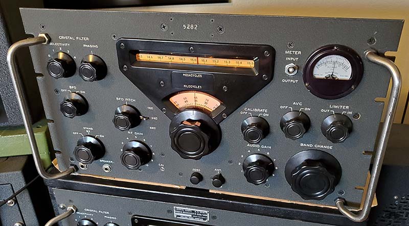
Apr 30, 2023 - I set-up sn:33 with the Collins 32V-1
transmitter and used both on the Vintage Military Radio Net this
morning. Conditions were challenging due to the high level of
atmospheric QRN but sn:5282 provided solid copy. I was using the NL, which
was okay, but the best results were reducing the RF Gain until the CL
meter read about +40db. Most signals were +40db or higher, so those
strong ones would still show the RF level on the CL meter and those
signals that were under +40db still could be copied. This reduced RF
(about 8.5) practically eliminated the QRN. The audio quality is the typical 51J-4 sounding
6kc MF AM
and is exactly as I remember the 6kc MF audio sounding on the two stock 51J-4 receivers I had years
ago. The best audio response on most
strong signals was tuning to the USB. Some of the weaker signals were
better tuning center frequency. Most strong stations were pushing the CL
meter to +55db, good average signals were around +40db (equivalent to
S-9.) KØDWC, at only 2 miles away, was at +60db. Tuning to
USB or LSB will affect the apparent dial calibration since you
essentially have to tune "off frequency" but, when tuned to
"center-frequency" (without any dial calibration performed earlier,) the
KC dial was only off 1kc which isn't bad. Operation of "break-in" via
K101 worked fine. I was using a 270G-1 Collins loudspeaker.
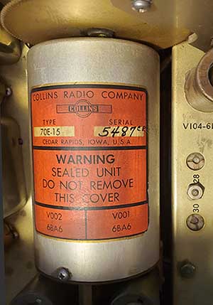
UPDATE: June 5, 2023 -
Although the BFO coil from the 51J-2 has been functioning fine in this
receiver, I did want to install a correct R-388/51J-3 BFO coil eventually. I
was able to purchase (off of eBay) a set of IF transformers and the BFO coil
that had been taken out
of a R-388. The BFO coil will be installed into SN:5282 to replace the
51J-2 BFO coil presently installed. Also, planned for SN:5282's return to
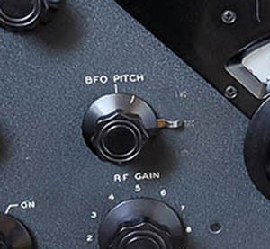
the workbench is to apply dry transfer letters-numbers for "1KC", "3KC"
and "6KC" since the lettering at present can hardly be seen. Lettering
size is 1/8" and the font that's closest is R R Gothic.
Color is white. The lettering that is present isn't even close as far as
the font type used and the placement of each group is too close to the
chrome switch lever. I'll probably have to apply a little "touch up"
paint first to hide these transfers and then apply the new, more correct
style with the proper spacing from the switch lever.
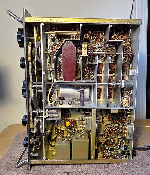
Back on the Bench
- June 22, 2023 - The 51J-3 was on the bench. The 51J-2 BFO had been removed and I was ready to
install the replacement R-388 BFO.
BFO Assembly Problem - I inspected the
replacement BFO closely because it's very easy to correct any problems
found now before the BFO is installed. Lucky that I "looked first." I noticed that the BFO
shaft was rough-feeling when rotated and there was a very slight "metal to metal"
contact sound. A closer look and I could see all of the variable-C plates were
shorted together. The plates weren't bent but the rotor had changed
position (probably the retaining clip came off) and that resulted in the rotor plates shorting
against the stator plates. I thought about
bending the plates to get the clearance but replacement of the
variable-C was actually the best option. Luckily, the variable-C in the original R-388 BFO was
okay. There are only three connections to the variable-C, so the transplant
wasn't difficult. Interestingly, I looked at all three variable-C components (51J-2,
R-388#1 and R-388#2) and all three were different. All three had
different part numbers stamped on their ceramic bases. The 51J-2 and
#1R-388 had the same number of plates but #2 had two less plates. NPO
capacitors were also different styles between #1 and #2. Obviously, these
were
minor variations in components used from different vendors throughout
the production runs and these variations don't affect the operation of
the BFO noticeably. So, the variable-C from the original BFO assembly was removed
and transplanted into the replacement BFO assembly.
MFP inside the BFO Can -
One thing observed was that the solder joints on the BFO assembly were
all MFP-coated (and this would be inside the BFO shield-can!)
This means that MFP-coating was a process that took place at all stages
of assembly, even at the component assembly level (since these types
of components wouldn't get MFP-coated with the final application, it had
to be done ahead of chassis assembly.) The transplant was slightly
complicated by the MFP since the solder joints had to be scraped cleaned
first, then "solder wicked," the wire unwrapped and the Variable-C
removed by dismounting the two screws and washers. The same steps had to
be performed for both the donor assembly and the assembly being
repaired.
Mechanical Alignment -
Once the transplant was complete, the BFO assembly was installed into
the "original to this receiver" shield-can, the BFO coupler installed and the
entire assembly loosely mounted. The alignment of the BFO shield-can to the
Mechanical Filter switch assembly is why the BFO can't be mounted
tightly at first. Once the BFO shaft is installed and the BFO assembly
and shield-can and
the BFO coupler all line-up, then the nuts can be tightened (under the
chassis.) Next, the three TC wires are connected and soldered. The
ground wire TC had been cut at sometime in the past and then
tack-soldered
with a glob of solder. I removed this wire and installed a new 18ga TC
wire soldered from chassis to the BFO terminal.
Test and Alignment - The
receiver was connected up for normal operation. Upon power-up, there was
no indication that the BFO was operational. But, I turned on the
Calibrator and tuned in the heterodyne for a good strong signal. By
turning the BFO on and off, I could hear that the BFO was coming on but
was "way off" frequency. I had pre-set the BFO vari-C for zero-beat
(half-mesh,) so the
main L adjustment was off,...and off by a lot!. I turned the L adjustment
about five full turns before I heard the heterodyne coming close to
frequency. It probably was off that much because the variable-C had two more
plates than the one that I had been removed. Anyway, I did a typical BFO
alignment and everything was working fine.
|
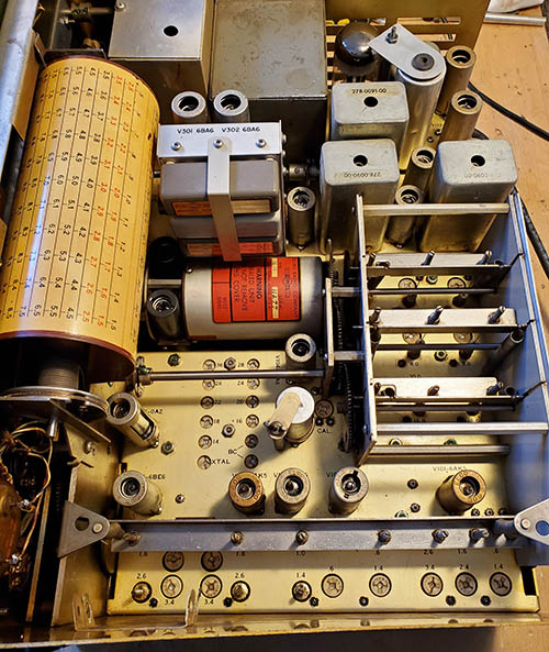
Dry Transfers for 1KC, 3KC and
6KC Nomenclature - I did a couple of tests to see if I
could actually apply these letters and numbers with the panel mounted
and all of the knobs in the way. The BFO knob and the MF Switch are in
the way. The escutcheon is in the way. The panel is vertical which makes
letter alignment difficult. The only way to do this lettering so that it looks
professional is to dismount the panel and dismount most of the parts.
The grab handles can be left mounted but anything the keeps the panel
from laying flat on the bench had to be dismounted. Once everything is
out of the way, then dry-transfer alignment of the lettering is much easier. I even did a practice run
using a "parts set" stripped R-388 panel and found that letter alignment is
pretty easy when the panel is stripped of parts and is laying flat. The
next step was to dismount the panel from SN:5282. I've done this
operation so many times it seems pretty easy now. I keep all of the
removed parts organized and safe which helps when it's time to
reassemble. I left the meter mounted but I did dismount the escutcheon. The
panel was now ready to get started with the lettering. The photo to
the right shows the 1KC, 3KC and 6KC nomenclature as it was
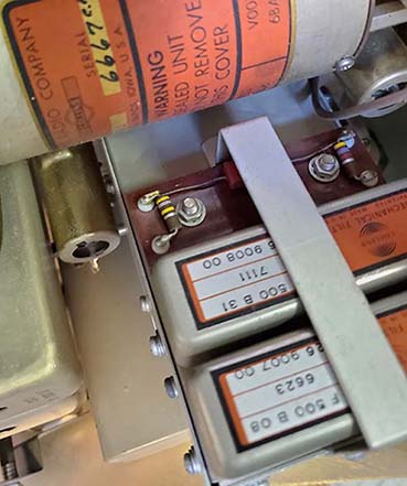
originally. Very faded and not the correct font. |
 |
Touch-ups and Pre-alignments
- I thought it would look better if I completely covered the old
extremely faded MF nomenclature. They were too close to the MF switch
lever so they would show a little if I left them. I used matched St.
James Gray paint and used just barely enough to cover the old lettering.
I had to mark in pencil where the MF switch positions would be to have a
letter alignment point (when finished the pencil marks were covered with
the St. James Gray paint.) I used to do this type of dry transfer
lettering quite a lot on prototypes and on test fixtures where I used to work, so
I've had considerable experience with dry transfer lettering. Trouble
is, that was over 30 years ago,...but I think I still remember how to do it.
The 51J-3 panel is
sort of easy because it already has a lot of nomenclature on the panel
that can be used for reference alignments. The dry transfer letter sheet
will have alignment lines along with observing the line along the tops
of the other letters that will help keep the position of the transfer
sheet straight. I had to use the MC dial cut-out edge for a straight
reference along with the alignment lines on the transfer sheet. The
letters and number
really have to be close to perfect in being straight and spaced evenly.
If well-done, the lettering will look original,...even if the font is
slightly different from what Collins used. The other thing that really
helps is each position only has three characters, a number and two
letters. That's much easier to keep straight than long words or multiple
words on one line. Three characters is nice.
"Toning Down" and Added Protection
- Once the application of the transfers was completed it was obvious
they were "bright white" which wasn't totally unexpected. Although the
other original nomenclature looked really white, it wasn't, since it had
years of aging that had discolored it somewhat. I had to "tone down" the
new white nomenclature to match the aged nomenclature but whatever I
used to do that had to be colored but transparent. I thought it would be a good idea
to experiment first since the dry transfer application looked
really good except for being very white. I applied some dry
transfer letters to the "parts set" R-388 front panel and began
to experiment. I tried dark tea, Polyshades Walnut and Artist's
Acrylic gray paint mixed with tea. The last two worked pretty
well with Polyshades doing the best at a match. The added benefit is that the
instructions for the 354A-1 kit indicated that the decal originally supplied with
the kit should be coated with clear lacquer for protection, so the
original MF conversions had a coating on the 1KC, 3KC and 6KC
nomenclature. I applied the Polyshades to the 1KC, 3KC and 6KC
nomenclature with a very small paint brush with very light
coatings to "work up to" the best match. The Polyshades has to
dry for a few hours before the lettering could be touched,...if
you wanted to touch it.
|
Reassembly and Testing -
While I was reassembling the receiver I happened to push against the MC
dial drum and it physically moved to the right somewhat. I saw that both
mounting brackets moved. Unbelievably, I found yet another
"missing screw and lock washer." The left bracket had both screws but
they weren't tight at all. The right bracket had only one screw and it wasn't
tight either. Strange that the screws that were present had their lock washers. A 6-32 RH
Phillip's machine screw and external tooth lock washer was installed and
all mounting screws for the brackets were tightened. Guess I missed that
one,...until now. No other issues. Bottom cover installed and top cover
installed to complete assembly.
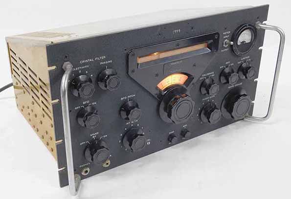
UPDATE: Oct 27, 2025 - Performance Test
- It's been a while since I've operated this receiver so I connected it
to the Pixel Loop antenna and attached a 4Z loudspeaker. On the 26th
there was a ham contest so 20M was loaded with signals. I went up to 15M
and heard some JAs and some CE stations. Copied XSQ 16.874mc and Trenton
Military 15.035mc USB. Also, a "Numbers Station" on 15.015mc USB
although the transmission was using phonetics and in English. Good
performance, especially considering I was using the Pixel Loop. The next
day I tried the Collinear Array antenna and that was quite a noticeable
improvement. XSG copied on 16.896mc out of Shanghai, China, another
maritime CW beacon that's a little more difficult to receive than XSQ
(Guangzhou, China.)
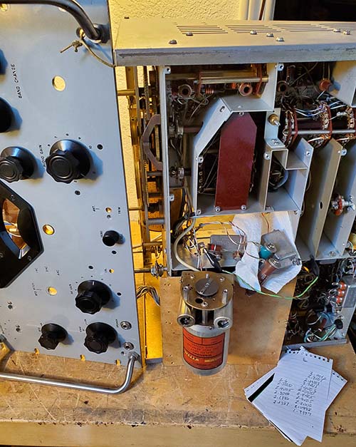
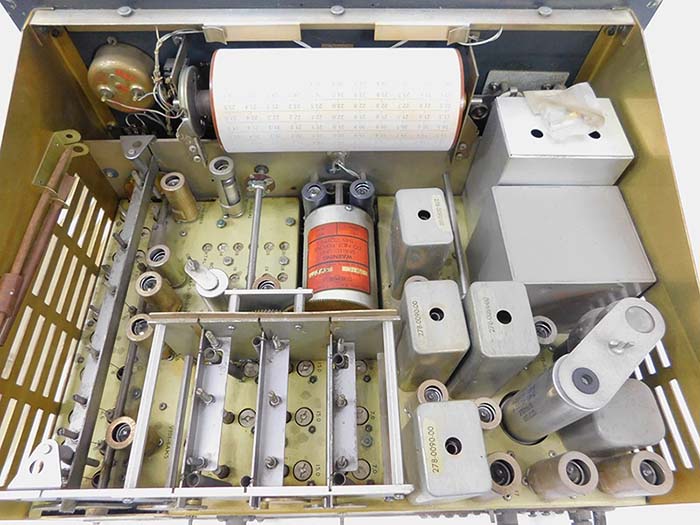
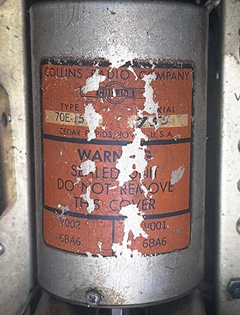
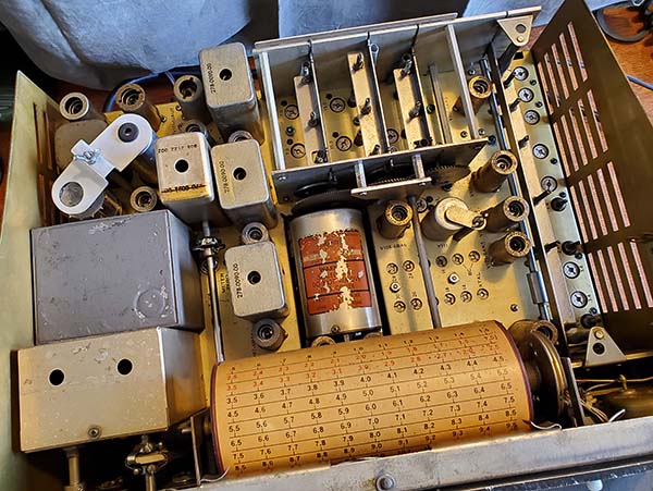
UPDATE: Dec 19, 2025 - PTO Calibration
- A few days ago I decided to try calibrating a spare 70E-15 PTO I had.
The EPE on this spare was an unbelievable 15kc! Yet, with about four
adjustments of L002, I had the EPE at <1kc and the linearity was about
1kc. The ease of that calibration got me thinking about the PTO in
SN:5282 with its EPE of 8.5kc. This was going to be a more formidable
project in that this PTO had be dismounted from the receiver in order to
do the calibration. It took about an hour and a half to disassemble
SN:5282 to the point where the PTO was "hanging" by its wires but ready
to calibrate. Again, I was surprised that with about four adjustments of
L002, I had the EPE at <1kc and the linearity deviation was about 1kc. Receiver
reassembly took another one and a half hours. Then I thought that I
better realign the entire front end of the receiver using the correct
51J-4 dummy antenna (I just used a 47 ohm resistor before.) I was
surprised to find that I hadn't really adjusted all of the Crystal
Oscillator trimmers. It also appeared that I didn't do the 16mc to 30mc
tracking alignment either. Most of the adjustments were close but
several were quite a bit off. Now, SN:5282 has "dead-on accurate" KC
dial readout (like a frequency meter) and has excellent performance on
all bands. |
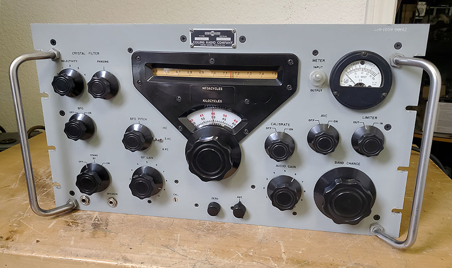
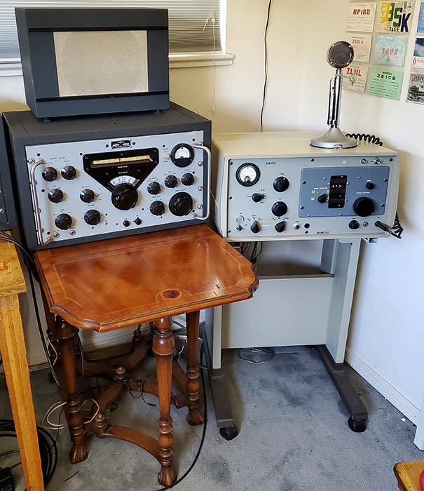
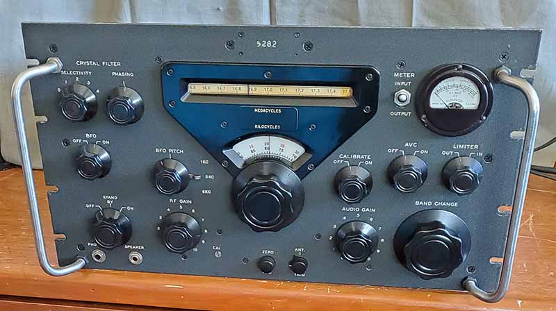
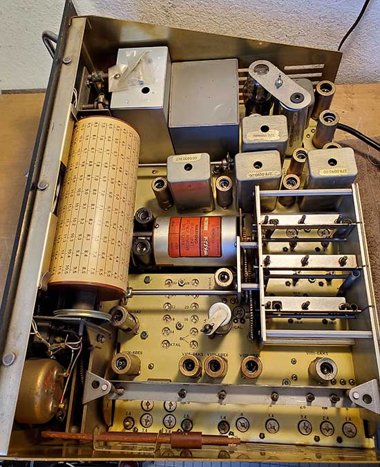
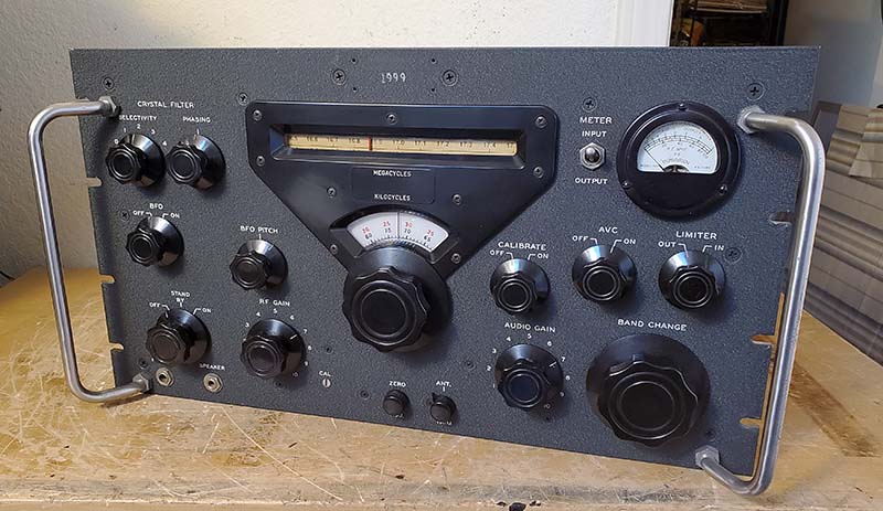
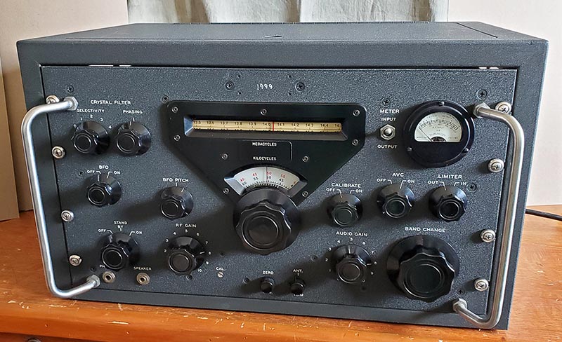
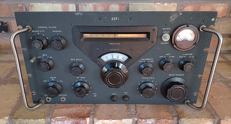
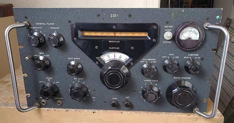
51J-3 converted to 51J-4 CMSN:5282 was back on the bench in December
2025. The work was to actually calibrate the PTO in this
receiver to <1kc EPE and ~1kc linearity. This was followed by a
complete front end alignment. SN:5282 is "dead-on accurate" with
great performance capabilities now. The receiver is tuned
to Trenton Military 15.035mc USB VOLMET from Trenton, ON, CAN
using the Collinear Array Ant - 1500hrs PST 12-20-25 |
|