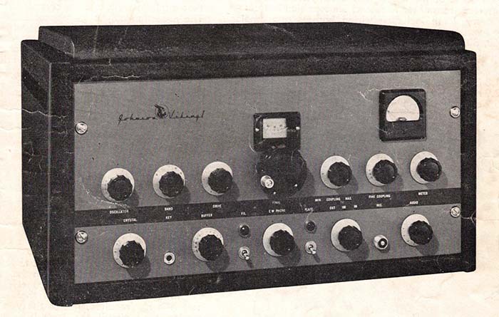
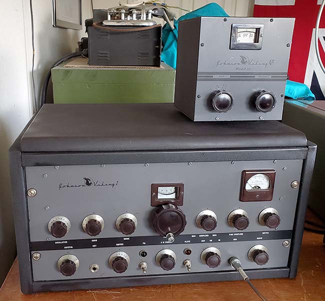
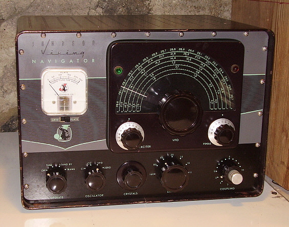
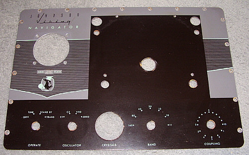
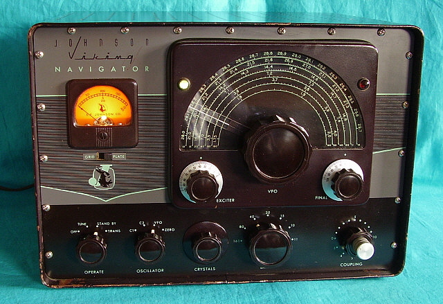
| Panel Touch-up - Dec 24,
2025
- I bought Testor's model paint in brown, gray and black, both in flat
and in gloss. I also had on hand blue, red, yellow, white and
green,...just in case. I was reasonably sure that the gray had a lot of
brown in it. The brown had a lot of black mixed in with it. The brown
was matched only using gloss brown and flat black. The mix of flat and
gloss gives the paint a matte finish which was like the original paint.
The gray was very difficult to match. It took gray, black and brown with
just one drop of blue. Luckily, most of the missing paint was located
where knobs or bezels would cover the touch-up. The "METER" nomenclature
was missing but I had the correct size dry-transfers but could only get
close on the font. Probably not noticeable at a casual glance. With
all of the knobs, the meter and the bezel mounted, the touch-up job is
pretty good. Certainly apparent if you know about the work that was done
but probably not noticeable unless pointed out.
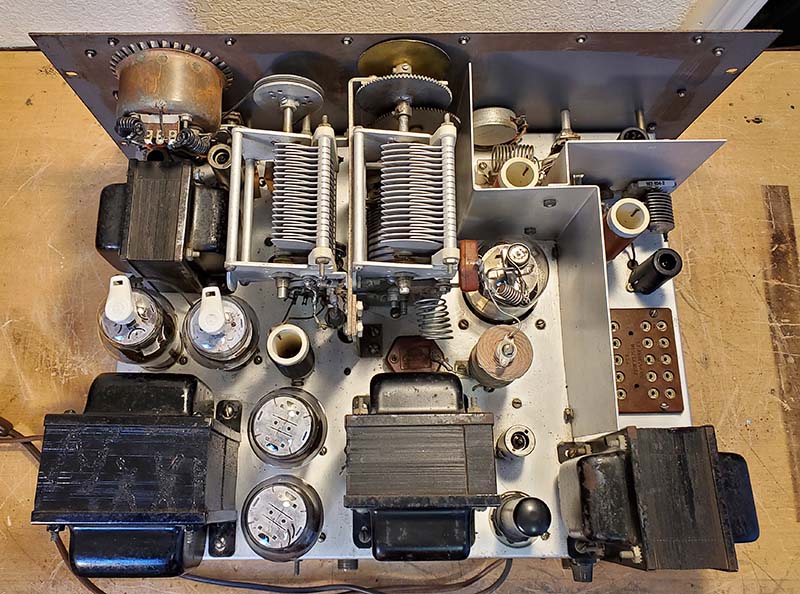
Meter Problems - Dec 29, 2025- I
thought I was going to be using the same meter that had been in the Viking 1 before. I
tested it thoroughly and there's nothing wrong with the suspension and
the meter is fairly accurate. I suspect the problem is probably in the meter
switch soldering or the shunts. The wires are just pushed through the terminals and
soldered. With solid wire, there might be a cracked solder joint or
maybe one of the solid wires is cracked. Eventually, I ended up replacing this
meter with the one that I had tested (that had the cracked case) because
the latter meter was more linear over all.
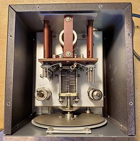
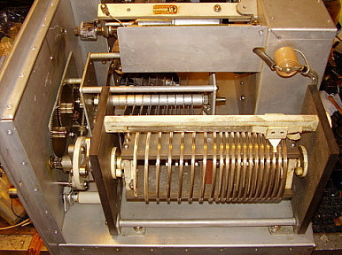
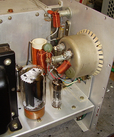
Plate Tuning Bezel, Index and
Rotating Scale Problems - Probably because the
transmitter Pi-network was built using two different sets of parts,
nothing really fits together exactly. I actually find that the bezel
fits better and mates with the scales better if it's mounted upside
down. Not really noticeable unless it's pointed out.
Too Much Plate Current, too little Drive,
Other Issues - Dec 31, 2025
- I suspect that something is wrong with the shunt for Plate current.
For 100 watts output, the Plate I on the meter shows about 400mA. It
should be around 275mA. That should be with 12mA of grid drive but I
when set to 275mA Plate I, the drive is barely above 0 and the power
output is about 25 watts. I measured the
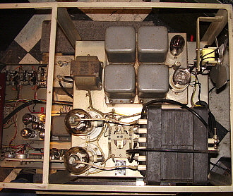
transmitter power supply voltages and found +630vdc plate voltage and +330vdc for screen voltage.
+LV measured +320vdc. Bias voltages measured -70vdc, -30vdc and -16vdc. All
of the voltages seemed to be correct.
Since the meter actually
measures a very low current across a low resistance shunt, if that shunt
has a higher resistance than expected, more current flows through the
meter resulting in a higher reading on the meter scale. It might be poor
soldering, it could be the shunts are too long (they are made of short
lengths of coiled wire) or maybe the chassis
ground isn't very conductive.
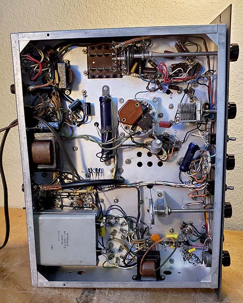
The problem ended up being poor soldering of
the shunts for both the Plate I and the Modulator I. Also, the ground
soldering on the shunts was very poor and the solder lug for the shunt
chassis ground wasn't tighten. I ended up removing the shunts
and moving the chassis-ground connection closer to the shunts location that only required about
a 1" wire to chassis. The shunt connections were cleaned and then the
shunts soldered back in place. I now had 110 watts RF Carrier output
power with 275mA of Plate I and the Drive was at 12mA grid current with
the Drive control set on about 4. This all looked correct. I switched to
MOD to measure the idling modulator Plate I and it was measuring about
30mA,...it should be between 60mA and 80mA. I readjusted the divider
resistor to slightly increase the screen voltage and that got the modulator
Plate I up to 70mA with +350vdc screen voltage, which is correct. I had to redo the solder on the
divider resistor terminals also. In fact, the entire transmitter looks
like it was assembled poorly with wire leads just pushed through
terminals and then soldered. No wire wraps at all. The soldering looks
like really cheap solder was used. Certainly not Kester 60/40 SnPb,...maybe just a
soldering iron that was too cold. Fortunately, by now, with all of the
rework that's happened over the past 17 years, most of the solder joints have been
corrected,...hopefully. Another Error
- In looking over the schematic, I happened to check over the bias
divider network and noticed that I had connected a 2.7K resistor in
parallel with the 1.5kc resistor to lower the bias on the modulator
tubes to -30vdc. I decided to just rebuild this divider network so the
bias voltages would be correct. I ended up removing the ground
lug that was tightened and redoing the divider network chassis ground
connection. I replaced the out-of-tolerance 1.5K resistor using an A-B
1.5K 2W 5% CC resistor. The bias voltages are now -77vdc, -33vdc and -22vdc
which should be close enough. I ended up entirely removing the 20K
100W WW adjustable voltage divider for the screen voltage adjustment since it was poorly
soldered and any adjustment of the slider seemed to not make contact. I
thoroughly cleaned the resistor, removed the rust from the inside of the
slider, remounted the resistor and soldered the wires to the terminals.
Now I had, +320vdc screen voltage and +600vdc plate voltage. Which looks
very close to the specified voltages. BUT, when measuring the Modulator
idling current it indicates about 40mA. It should be between 70mA and
90mA but that would require either lowering the modulator grid bias for
which there's no adjustment. Or, the modulator screen voltage could be
increased. The manual indicates about +280vdc modulator screen voltage
under load but the schematic indicates +300vdc. With the screen voltage that low the idling current would be
even lower than it already is.
Correct Voltage Dilemma
- So, what's correct,...the Johnson schematic, the Johnson manual or the
RCA tube manual? None of these documents agree on expected voltages or
currents. I had to slightly change the resistor values in the bias
network to have -74vdc which is the bias rectifier output and can't be
easily changed. Then I set the modulator grid bias for -30vdc which is
the tube manual spec if the plate voltage is +600vdc and the screen
voltage is +300vdc. I had to set the 20K divider quite different from
where it had been set since the screen voltage had been running about
+380vdc and +300vdc is maximum screen voltage rating for the 807s. The
bias voltage for the buffer tube is -17vdc which seems to be fine. The
Viking 1 manual says to adjust the 20K divider for 70mA to 90mA of
modulator idle current but that would require the screen voltage to be
set to about +400vdc! With ALL of the 807 voltages very close to the RCA
tube manual specs for a P-P 807 modulator, I get 40mA of idle current.
That is, with +290vdc screen voltage, +610vdc plate voltage and -30vdc
grid bias voltage. I double-checked the idle current by pulling one end
of the shunt and inserting a Triplett 630 to measure the current,...it
measured 35mA, so the Viking 1 panel meter is fairly close. Running into
the Collinear Array at a 1:1 match, I have 275mA of plate current with
12mA of grid drive. The power output is 110 watts on 3.974mc. The
modulator idle current is 40mA. The audio has never sounded better and
watching the 'scope pattern I can see lots of excellent positive peaks
and negative cut-off happening fairly often. My thought is that Johnson
was providing a kit and they wanted to make sure assembly didn't require
in-depth measurements and certainly not any hand-selecting component
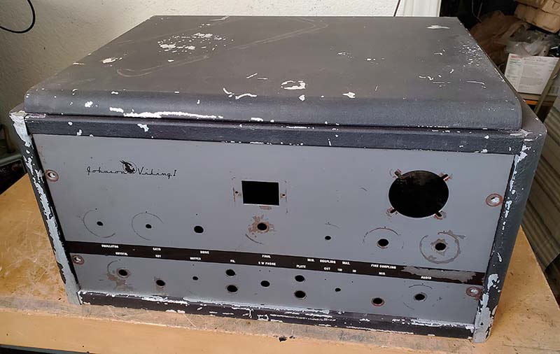
values,...even though the expected builders would have been hams. The Aluminum Cabinet
- The two lower front panel mounting threaded holes were stripped and the
holes enlarged too much to really do any type of repair. I tried installing clip nuts
but the type I have (standard size 10-32) puts the hole too far inwards
for the front panel holes to align. Clip nuts are the best solution
so I had to modify the cabinet's mounting lip to allow the clip nuts to set
outwards about 1/8" which then would have the hole align with the
front panel holes. First, the 10-32 holes that were stripped and the two
that weren't stripped had to be drilled out to 5/16" for the clip nut to
seat correctly. Then I had to use a file to
recess the mounting lip edge with about an 1/8" notch that would allow
the clip nuts to seat correctly and align with the front panel holes. I
used the old Viking 1 TVI front panel as a template to make sure the
holes were in alignment. The four panel mounting holes now have clip
nuts installed which then allows the front panel of the transmitter to
be tightened up securely. Since the clip nuts have an actual steel nut
behind the clip the front panel screws can be tighten as needed.
Still More Problems -
When the Viking 1 was installed into the cabinet and connected to the
station antenna with the waveform monitored on an oscilloscope, the
transmitter wave envelope was at the expected amplitude initially. After
a few seconds to maybe a minute, the waveform amplitude suddenly dropped on the 'scope but the watt meter still
showed 100 watts output. SWR changes slightly but can be adjusted to a
null using the Matchbox. Still, the waveform amplitude on the 'scope
showed greatly reduced amplitude (peak to peak) but the watt meter showed
100 watts carrier power. Using a different transmitter but the same T-R relay, same
coax from the T-R relay to the Matchbox, no problems were encountered.
Interestingly, I listened the Wavelength Radio recording of the net so I
could hear what the Viking 1 transmission sounded like,...I didn't hear
anything. I think there's a problem in the Pi-network or maybe the plate
blocking capacitor. It looks good on the plate current meter but
apparently the actual signal isn't getting through the Pi-network. As to
why the watt meter shows 100 watts when there's no output,...most watt
meters are only accurate when the SWR on the line is 1:1 and as the
mismatch increases so does the indicated RF output power. It might be
that the Pi-network problems are causing the erroneous watt meter
indications.
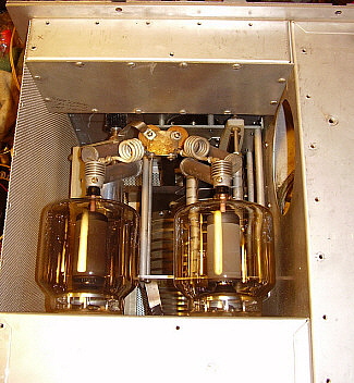
Nothing obvious was found
- The plate blocking capacitor tested good but the mounting was very
loose. It uses a "L" bracket mounted on one of the studs of the
frame of the roller inductor in the Pi-network. The bracket had to be dismounted to tighten
the capacitor screw (which was why it hadn't ever been tightened before.) I
also soldered the bias network resistors again. I also replaced the 6AL5
bias rectifier because one of the diodes tested low. I tested the
transmitter chassis on the
work bench by running a 50ft length of RG-58 from the bench over to the
ham shack to connect to the antenna. Everything looked good. I moved the
transmitter chassis into the ham shack and connected up everything
again. I made sure I was going through the T-R relay. Once again,
everything looked fine on the oscilloscope with 105 watts carrier power
indicating on the watt meter. I'm going to test multiple times in this
configuration before I put the Viking 1 back into it cabinet.
Jan 13, 2026 - Testing
consisted of three sessions, each session had the Viking 1 chassis
powered up for about 45 minutes and, during that time, three different
times a signal was transmitted via the Collinear Array at 105 watts of
carrier power, fully modulated. Each test transmission was about 30
seconds to 1 minute duration. Waveform monitoring was using the FNIRSI
oscilloscope. A total of nine transmissions were made. No problems
during any of the transmissions. |