Radio Boulevard
Western Historic Radio Museum


NATIONAL  COMPANY,  INC.

 HRO  - COMMUNICATION RECEIVERS - "The Cream of the Crop"

   PART 3

Guide to Restoring the HRO Receiver, PW-Gear Box, PW-Dial, Hints & Suggestions

Restorations in Detail - 1935 HRO SN: H-103,  1940 HRO Senior SN: 463-K 

 
by:  Henry Rogers WA7YBS

PART 3
 

Guide to Restoring the HRO Receiver

Though much of the restoration process is similar to any other vintage receiver's restoration, the HRO does have some specific parts the require special knowledge and techniques to restore or to duplicate. The PW-D Micrometer Dial section below is very detailed since it is quite easy to reassemble this device incorrectly. The PW-Gear Drive below is also detailed for the same reasons. In addition to the restoration and rebuilding information, five specific HRO restorations are profiled. These sections show the various restoration problems that are encountered during the process and each restoration is shown from beginning to end with lots of photographs.


PW-Gear Drive and PW-D Micrometer Dial - Detailed Information

The heart of the HRO is its fabulous PW-Gear Drive and its PW-D Micrometer Dial. These incredibly engineered components working with the precision tuning condenser and the innovative coil sets account for the HRO's top performance, both electronically and mechanically. Unfortunately, almost every HRO receiver encountered will have problems with the PW-Gear Drive or the PW-D Micrometer Dial, or both. Most problems found will be traced to incorrect reassembly by former owners. The following section gives the HRO owner detailed information on how to correctly disassemble, service and reassemble the PW-Gear Drive and the PW-D Micrometer Dial. "PW" was National's designation based on the gear drive's use of a "precision worm."

Lubrication and Assembly of the PW Gear Drive  

The Cast Metal Gear Box - Every HRO I've worked on has needed servicing of the PW Drive Gear Box. Usually, when the top cover is removed, it will be apparent that the old grease is very dry and not coating where the gears mesh. Also, you might find that the split-ring anti-backlash gears are stuck from old dried grease that prevents the anti-backlash from working. You might even find that the worm gear shaft is assembled incorrectly. Down where the worm gear is located can't be seen from the top. To fully service the PW Gear Drive requires disassembly. To check the worm gear assembly the elliptic bearing hub has to be removed. Be careful when removing the last screw that holds the elliptic bearing hub in place because the worm gear shaft thrust is spring-loaded. Hold the split-ring gear together with your fingers as you remove the worm gear for inspection and lubrication because the split-ring gear is also spring-loaded for anti-backlash. As you remove the worm gear, note how many teeth backlash is set on the split-gear - it shouldn't be more than two teeth. Clean all of the old grease off using a stiff tooth brush with WD-40 or some kind of light oil. Then apply a light-weight grease like Lubriplate to the gears. A small amount of light oil should be worked into the split-ring gears so they can easily move. Be careful of the three springs that load the split-gear. They sometimes come off their mounting pegs but they are easy to reinstall.

Note how the worm gear shaft is assembled. It's not uncommon to find the HRO gear drives assembled incorrectly. Look at the National artwork to the right. This shows the correct assembly of the worm gear shaft, washers, spring and the ball bearing. Note from the worm gear flange there is a ball bearing, then a washer, a spring and another washer. The assembly is held in place by the elliptic bearing hub. The ball bearing appears to have no support but the design is for the ball bearing to apply thrust force against the shaft flange without an excessive amount of friction. The worm gear thrust bearing can be assembled in reverse order and the drive works okay but National's design provided minimum friction from the thrust force.  >>>


photo above: The Early HRO PW Gear Drive (Cast Metal) - enlarged for increased detail  - provided by: Charles Hentsch

>>>  It's also possible to assemble the worm gear thrust bearing with the ball bearing reversed. This will not allow the ball bearing to rotate properly. Usually the side of the ball bearing with the stamped identification should be facing the flange. However, it's best to test whether or not the ball bearing will rotate correctly. Do this by assembling the thrust bearing on to the shaft. Then hold the pointed-end thrust bearing against a piece of wood by pressing against the spring with your fingers. Then rotate the worm gear shaft with the fingers of the other hand. If the thrust ball bearing is mounted correctly, the outer housing of the ball bearing will not rotate but the inner race will. If the bearing is incorrectly reverse mounted then the outer housing of the ball bearing will rotate with the shaft.

To reassemble the gear box first apply some light-weight grease (lots of lithium-based greases available - just don't use Lubriplate because it is a "sliding" type of grease, not for gears) to the conical thrust bearing of the worm gear as this is spring loaded against a mating conical thrust bearing that is machined into the cast gear box housing. Don't over lubricate any of the individual parts by packing the gear box full of grease since the thrust ball bearing and the split-gear must be able to move easily which is difficult when either part is loaded with grease. Be sure to thoroughly clean the thrust ball bearing as it is essential to the design that this bearing moves easily. Use a very light oil and grease mixture for the ball bearing. Lube the worm gear with light-weight grease. The split-gear looses its anti-backlash position for spring loading when the worm gear is removed (the "loaded" position is held by the worm gear) - just rotate the two gears in opposite directions a couple of gear teeth while engaging the worm gear. Be sure to watch the split-gears as it is common to have the anti-back lash setting slip as the worm gear is inserted into position. Check the anti-backlash tensioning springs to be sure they are installed on their pegs. Lube the inside of the elliptic hub with light-weight grease. Reinstall the elliptic bearing hub casting which spring-loads the thrust on the worm gear. Note that one of the flanges is marked "TOP" so be sure to mount the the elliptic bearing hub housing with this flange up. This is important because it places the elliptic hub in the correct position to function with the PW-D micrometer dial. Check the gear drive for smooth operation and zero backlash.

The Cast Metal Gear Box is used from 1935 up to around 1945. The replacement Stamped Sheet Metal Gear Box was introduced with the HRO-5 and HRO-W receivers.

The Stamped Sheet Metal Gear Box - During WWII, the cast metal gear box was replaced with a stamped sheet metal housing. This was a cost-reduction that eliminated the difficult to machine cast metal gear box. Since the new sheet metal gear box was thin metal, it couldn't be machined to provide a thrust bearing at the rear. Instead a bronze bearing was pressed into the sheet metal to provide a thrust bearing. Also, since the sheet metal housing was thinner than the cast metal housing, the condenser supports were integrated into the assembly support of the gear box. This then reduced the clearance inside the sheet metal box and the thrust ball bearing assembly on the worm gear shaft had to be redesigned. With the sheet metal gear box, the thrust bearing assembly now had the ball bearing at the front of the shaft and the spring butting up against the worm gear flange. Also, the washers were eliminated and a brass fitting was installed to allow the spring force to be applied to the inner race of the ball bearing. If you try to assemble the thrust bearing like it was for the old cast metal gear box, it will not fit into the sheet metal gear box.

This reversal of the thrust ball bearing assembly on the worm gear shaft works essentially the same as the older assembly does and does provide a reduction in friction for the thrust force applied. The sheet metal gear box is introduced with the HRO-5 and HRO-W models (the new octal tube versions of the HRO for WWII production.) This dates from about 1945. All post-WWII gear box housings are similar in construction and include the HRO-5A, HRO-7, HRO-50 and HRO-60 versions.

The later version of the split-gear anti-backlash drive is heavily spring-loaded. Usually the split-gears can only be set to "one tooth" of backlash. Since the springs are very strong this "one tooth" loading is sufficient for removing any backlash. 


PW-D Micrometer Dial

The PW-D Micrometer Dial Design - The famous "micrometer" dial used on the HRO and several other National receivers was based on a Sperry Gyroscope design. The National "Micrometer Dial," or PW-D (PW-D is the National designation for the complete Micrometer Dial) doesn't change during many years of manufacture except for two very minor mechanical modifications made during WWII. Only two moving parts and eight stationary parts are used in this elegantly simple design. The following are the parts used:

1 - Index Dial (or Outer Dial  - moving part 1)
1 - Number Dial (or Inner Dial  - moving part 2)
2 - Retainer springs (holds Number Dial to Index Dial)
1 - Knob - HRK type - (mounted to Index Dial)
3 - 4-40 Flat head machine screws (to mount knob to Index Dial.)
1 - Set Screw (during WWII - two set screws)                                          

How the PW-D Works - The PW outer Index dial by itself will not not turn the inner Number dial - it must be used with the PW Gear Box that has the elliptic hub mounted on the front of the gear box. The elliptic hub actually provides the eccentric that always forces engagement of the inner Number dial gear teeth to the gear teeth of the outer Index dial as the PW-D is rotated. The gear teeth are located on an embossed rim inside the outer Index dial and are cast into a circular recess in the inner Number dial. All of the parts must be assembled together correctly and the PW-D must be mounted on the elliptic hub of the PW Gear Box in order for the micrometer dial to operate and indicate properly.

 PW-D Mechanics - Internally, all PW-D dials are the same and work by rotating the Number Dial on an elliptic hub. The Number Dial is gear-driven by the Index Dial that is also set-screw coupled to the main tuning shaft of the PW gearbox drive. Turning the Index Dial simultaneously turns the Number Dial and the HRO Tuning Condenser via the PW gearbox. The Index Dial has five windows with ten index marks between each window. The Number Dial displays sequential numbers that increment by 10 as each window comes into view at the top of the dial. Only the when a window is at the top of rotation is a particular number centered and easily readable. The Number Dial has 0 to 500 numbers incremented by 10 and each revolution of the Index Dial increments the numbers by 50 (five windows viewed with each revolution.) With ten revolutions total of numbers displayed is 0 to 500 incremented by 10. Since the Index Dial is 4.625" in diameter, its circumference is 14.53" and with ten revolutions the total span is 145.3" or just over 12 feet (12.1'.) When HRO coil sets A, B, C or D are set to band spread then the ham bands each span 50 to 450 on the PW-D. This is 80% of the full 500 divisions thus the ham bands equate to a linear dial that is 9.68 feet long.

As to the two moving parts (Index Dial and Number Dial) and seven stationary parts - besides the Index Dial and the Number Dial there are two springs that hold the two dials together, three flat-head screws to mount the HRK-style knob to the Index Dial and a single set screw on early versions. During WWII the set screws were increased to two. Elegant in its simplicity, about the only thing that ever goes wrong with a PW-D is caused by technicians who carelessly disassemble the dial and then reassemble it incorrectly. More details on how to disassemble, service and reassemble the micrometer dial in the "Lubrication of the PW Gear Drive and PW-D Micrometer Dial Assembly" section further below.

PW-D Evolution - The first PW-D had a flat nickel finish on the outer Index dial with black index graduations. The inner Number dial was also nickel plated with black numerals. German Silver was used on the smaller HRO knob skirts. German Silver is an alloy made of copper, nickel and zinc. Since the PW-D dial is cast metal, it can't be solid German Silver but is actually German Silver plating. Generally, the PW-D was supposed to appear "flat white-silver." By 1936, with the introduction of the NC-100, a number of different lacquer finishes were used for the PW-D. The HRO Senior and Junior PW-Ds will be found with paint that varies from dark gun-metal gray lacquer finish to a dark bronze lacquer finish. These varying paint colors appear black except under intense light. NOTE: In the photos below of both the HRO Sr and Jr PW-Ds. These colors will generally appear black in normal room light but under the intense light of the camera "flash" the true color shading is seen. The white index lines are very narrow on early PW-Ds and seem to become slightly wider during WWII.


Early HRO - German Silver Plated


HRO Sr/Jr- Lacquer Paint (Gun-Metal Gray)


HRO Sr/Jr  - Lacquer Paint (Dark Bronze)


HRO-W - Bronze Lacquer & MFP


HRO-60 - Matte Chrome Plating

The PW-D for the NC-100 was blue-gray on the outer dial and red with white numerals on the Number dial. Some NC-100X used a gray Index dial and the HRO type black Number dial. The gray PW-D was also used on the National Airway Communication Receivers that were based on the NC-100 receiver. These receivers generally have gray PW-D Index dials with black Number dials with white numerals. 

It seems probable that Doehler supplied the PW-D castings to National and the painting was done at National. There are so many color variations that it seems unlikely Doehler would have stocked the paint and been able to keep track of the order requirements. It's more likely that National painted the PW-Ds as required. This probably also applies to the German Silver plated PW-D since National did their own plating.

When the NC-101X was introduced, it usually was fitted with the same "black lacquer" PW-D as the HRO, although early versions are sometimes seen fitted with gray Index dials. Some pre-WWII military HROs were fitted with light gray PW-D dials. During WWII, some HRO receivers were moisture and fungus proofed (MFP) which sometimes included coating all of the knobs and the PW-D Index dial. MFP gives the outer Index dial an olive-drab appearance. 


photo above: The gray with red number dial PW-D used on the NC-100 receivers.

After WWII, the HRO-5A series goes back to the dark bronze finish for the PW-D with some exceptions that may have resulted from National "cleaning house" and thus early dark gun-metal gray dials do show up on post-WWII HRO receivers. When the HRO-7 was introduced the PW-D was given a light gray paint job to match the changes that the HRO-7 cabinet featured. The HRK knob was also changed to an HRT style knob. Some rack mount HRO-7R receivers were finished in wrinkle black and these receivers will have the standard "black" PW-D dial installed. The HRO-50 returned to a nickel or chrome finish to the outer dial with the inner dial black with white numerals. The HRT style knob was retained. The HRO-60 returned the HRK knob to the PW-D assembly. The HRK knob was also usually installed on the HRO-50 if it was rack mounted.

Throughout this evolution only one minor mechanical change to the design was incorporated. During WWII a guide pin was added to the inner wheel which helped with alignment and made installing the PW-D onto the elliptic hub somewhat easier. Additionally, a second set screw was added, probably to meet "military specifications."

National, at times, seemed to use whatever PW-Ds they had in stock - or maybe, in "excess" stock. It's common to find late-thirties HRO receivers with gray NC-100-type PW-Ds. Gray PW-Ds will also show up on early NC-101X receivers and on all National Airway Receivers. Examine such variations for authenticity but don't be surprised to find that the PW-D is original to the receiver.

Repainting the PW-D - A lot of the PW-D Index dials will be in poor condition with chips, scratches and worn surfaces. Additionally, sometimes a receiver will be found that obviously has a later PW-D installed. The upshot is the PW-D Index dial will need repainting. I've been able to get automotive paint shops to successfully custom match a PW-D Index dial, even the dark bronze-black color. Only use high-quality auto-motive paint for this restoration process. Use Artist's Acrylic white + raw sienna + black to create a beige manila color for the index lines. Don't use lacquer stix or bright white paint. The manila color will look correct. Be sure to let the PW-D paint cure for at least four or five days before doing the index lines. It's rare for the Number dial to need a repaint.

PW-D Micrometer Dial Assembly

The PW-D Micrometer dial only has two moving parts and seven stationary parts. Elegant in its simplicity of design, it is very easy to work on if you know the "tricks." About the only thing that goes wrong with the dial is that it becomes noisy in operation and might have a rough feel when tuning. Synchronization might be a problem too - if the dial was reassembled incorrectly. The inner dial has gear teeth cast into its inner perimeter and also has the bearing that fits on the elliptic hub of the tuning shaft bearing housing. The outer dial has mating gear teeth that are cast into a rim projection and a hub that is set screw attached to the tuning shaft. By having the inner dial ride on the elliptic hub cast into the tuning shaft bearing housing, the gears of the two dials engage and as the outer dial is turned, by way of the mating gears, it turns the inner dial and since the outer dial is coupled to the tuning shaft, it also moves the tuning condenser. The elliptic hub is actually round but since the tuning condenser shaft exits the hub "off-center," the hub bearing surface appears as an ellipse to the tuning condenser shaft. This eccentric placement forces engagement of the inner and outer dial gears, thus driving the inner dial with the rotation of the outer dial.  >>> >>>  To disassemble the Micrometer dial, first tune the receiver to "250" then loosen the dial set screw. The dial should come off of the elliptic bearing hub and tuning condenser shaft with very little effort. If the PW-D dial is hopelessly stuck, read the section below "Dismounting a Stubborn PW-D" for the removal procedure if this problem is encountered. With the PW-D dismounted, look at the back of the dial and, if the PW-D was synchronized prior to removal, you will notice that the three screws that hold the knob to the dial appear through cast holes in the inner dial. Also note that the two springs that hold the inner dial to the outer dial are pointing straight up. Remove the knob. Then remove the two springs - their ends fit into slots at the end of the shaft hub of the outer dial (where the set screw is.) Now the dials can be separated. Examine the cast gear teeth for condition. Usually they are in good shape and all that is present is old dried grease. Use a tooth brush and light oil to remove all of the old grease and then apply a light coating of Lubriplate to the inner dial gear only. Position the inner dial to the "250" position with the cast holes lined up for the knob screws. Then install the two retaining springs. >>>

>>>   Before putting the PW-D back on the receiver, lightly grease the elliptic bearing hub (since the inner dial rides on this it should be clean, smooth and lightly greased.) Verify that the elliptic hub has the "TOP" embossing on the flange at the top. This places the elliptic in the correct position for the PW-D gears to engage. The PW-D should already be set to "250" and the receiver condenser should not have been moved. Place the PW-D back on the receiver by carefully noting how the elliptic hub requires the inner dial to be slightly down from center. If you have assembled the PW-D correctly, it will just slip right on to the hub. Tighten the set screw and test the operation - it should be ultra-smooth and very quite in operation. If your PW-D dial doesn't just slip onto the elliptic hub then it isn't assembled correctly. The PW-D can be assembled several ways but only one way is correct. There are no exceptions to this - if the PW-D doesn't slip right onto the hub then it is assembled incorrectly. If your PW-D doesn't just "slip onto" the bearing hub, read the section below "Correct Assembly of the PW-D Micrometer Dial - Details."

Around the beginning of WWII, a guide pin was added to the inner dial, located just above the inspection/grease hole. This pin limits the vertical movement of the inner dial and was probably installed to keep the gear alignment fairly tight and allow easier installation of the PW-D onto the elliptic hub. Later production dials will have this guide pin molded in the casting of the inner dial.


photo left: Two moving parts and seven stationary parts are all that are used in the PW-D. A second set screw was used during and after WWII - total of eight stationary parts then.

Correct Assembly of the PW-D Micrometer Dial - Details - When the PW-D is assembled correctly, it will just slip onto the elliptic hub. If you are trying to force the PW-D onto the hub, then the PW-D is assembled incorrectly - no exceptions. Look carefully at the photograph to the right noting the location of the smaller round hole, the two oval holes, the "NATIONAL CO., INC." embossing and the location of the screws that are for mounting the knob. If you orient the reverse side of your assembled PW-D in this position and then look at the outer dial, you should see "250" centered in the window that is directly behind the "NATIONAL CO., INC." embossing.

To check your assembly,...position PW-D as shown in photograph to the right. You should see the following:

1. "NATIONAL CO., INC" embossing should be at 12 o'clock

2. Small round hole should be at 9 o'clock

3. Two oval holes should be at 2 o'clock and 4 o'clock

4. Note that all three knob screws are directly centered in the small round hole and the two oval holes

5. Turn dial over from right to left and you'll see "250" centered in the window at 12 o'clock (the window should be directly behind the embossing "NATIONAL CO., INC" on the back of the inner dial.)

6. Push the inner dial down to make the "250" appear closer to the bottom of the window. You may hear a slight click as the gear teeth mesh but you might only "feel" the engagement. It helps to "rock" the inner dial while pushing it down.

If your assembled PW-D meets this criteria, then it will slip right onto the elliptic hub. You may find that, for some reason, the PW-D just doesn't want to fit onto the elliptic hub. Don't force it. When assembled correctly the PW-D will slip right on to the hub - no exceptions. If it doesn't, remove the PW-D and look carefully at the Number Dial bearing and its relationship to the tuning shaft hole in the Index Dial and note that the "off-center" nature of the opening is correct for the elliptic nature of the hub. Also, verify that the elliptic hub is installed correctly with "TOP" in the upper position of the mounting flange. If the all of these relationships are correct, then again, on the PW-D, very slightly push the Number Dial down to engage the gear teeth of the Index Dial to see if a better fit can be achieved between the gear teeth of both dials. You should hear a slight "click" when the "alignment slips into place" and is correct. Verify that "250" is still centered in the window of the Index Dial. At that point the PW-D will just slip right onto the elliptic hub.


photo right
: Correctly assembled PW-D micrometer dial looking at the back side. Although this photo doesn't show the relationship very well, the opening of the Number dial versus the shaft hole in the Index dial should "mirror" the shape of the Elliptic hub versus the tuning shaft in order to have the PW-D fit onto the hub without any difficulty.


Dismounting a Stubborn PW-D - Sometimes removing the PW-D Micrometer dial proves to be a very difficult operation. Almost always, the difficulty is caused by excessive marring of the tuning shaft by the knob set screw(s.) If everything seems it indicate that the PW-D is not coming off of the shaft no matter what, this is the procedure necessary to remove the dial. First, for pre-WWII HROs, you'll need a couple of right-angle screw drivers. I usually have to make them because everything commercial is too big to fit between the back of the front panel and the tuning shaft bearing hub screws. Make at least two that have different angles for the blade engagement. Next, remove the upper rail that is mounted to the back of the front panel and forms the front top piece of the cabinet. Now, using the right-angle screw drivers, loosen and remove the four screws that mount the elliptic bearing hub screws. This bearing hub is spring loaded for thrust so be careful removing the last screw. Now, remove the entire PW-D and the bearing hub and the worm gear out through the square hole in the receiver's front panel. Now, remove the knob from the PW-D assembly. This provides access to the front of the tuning shaft. Then, using a soft metal drift, gently tap out the shaft from the PW-D dial assembly. You will have to reassemble the gear box per the instructions in the "Lubrication of the PW Gear Drive" section above. Also, be sure to dress down the marring on the tuning shaft so the next time the PW-D has to be removed, it will be an easy job.  >>> >>>   For the WWII and later HROs, you'll need an open-end 1/4" wrench. Removing the top two hex head screws that hold the bearing hub is pretty easy but the two bottom screws will take patience. Usually only one hand will fit into the space between the back of the front panel and the tuning condenser, so, to remove the lower right screw, I use a small thin rod manipulated with my left hand fingers to lift the wrench onto the hex head and then turn the screw one flat with the wrench manipulated with my right hand fingers. Reposition, and again using the thin rod to help position the wrench, loosen the screw another flat. On and on, it takes awhile but you can get both of the bottom screws out that way. You'll have to change hands depending on which of the bottom screws you are removing, right or left. I usually take the bottom ones out first and then the top ones. Reassembly is easy since you can access the hex screws through the square opening in the front panel using a 1/4" nut driver.

NOTE: When remounting the bearing hub note that "TOP" is embossed on one of the flanges. This flange obviously must be mounted up. This is important because it positions the elliptic bearing correctly for the PW-D dial.


HRO Restoration - Hints and Suggestions

Manuals - Fortunately, the HRO didn't change very much from 1935 up to 1945 (including some obvious errors and outdated chassis photos that were not changed for years.) The receiver was so well thought out and so well designed, only minor tweaking of some component values were necessary but the manuals were very slow a showing any updates. As a result of this, all of the manuals will have minor glitches but almost any manual will provide enough correct information for operation, repair and alignment of most HRO receivers. Be aware that a few changes in resistor values occurred when the 6.3vac tube HRO Seniors became standard (~4/39.) The screen divider (R10 & R15) was changed slightly to provide a lower screen voltage for the newer manufacture 6C6/6D6 tubes. In the 1940s, National issued manuals that were usable for all of the HROs, e.g., the HRO, Senior, Junior, M, MX, RR. Later, the HRO-5 was also included in the compilation. These manuals are available as copies from several sources. If you are working on an early 2.5vac HRO be sure to use the earlier compilation for the correct resistor values (but don't be surprised if your receiver has original components that are slightly different than the parts list values.) As for original manuals, they are interesting to own but not absolutely necessary as an information source. Even the Rider's Perpetual Troubleshooters Manual Vol. VIII has enough information on the early HRO for repair and alignment. Capacitors - All paper-wax capacitors need to be replaced in any vintage receiver if you intend to operate the set more than just casually. In the HRO, all the capacitors are easy to access and replace. In fact they are so easy to get to, I usually go a step further in the restoration process and restuff the original capacitor shells with modern film caps. This is just a cosmetic issue and doesn't make any difference to the final performance but it preserves the original under-chassis appearance. The two cathode bypass electrolytic caps are riveted to the chassis with one of the rivet heads under an IF transformer shield. They can be dismounted, rebuilt and re-riveted - if you are a purest. Also they can be left in place, disconnected and the new replacement electrolytic cap mounted nearby if under chassis appearance isn't an issue. Actually, these two electrolytics were well built and some of the originals might be usable. They were very low voltage (25vdc) and were well sealed - just test, reform and, if good, use.
Ceramic Lead-end Resistors -  National made their own resistors. They consist of a piece of ceramic round stock that has been drilled lengthwise to accept small diameter carbon rods. The rods protrude out the ends and when the lead-end was cast, contact was made with the carbon rods. Usually two rods are used on larger resistors and one rod on the small size. Over the years the contact to the carbon rod(s) may become compromised or maybe the rod(s) will crack - either will cause the resistor value to change significantly. Usually a restorer will find at least a few of these National resistors that need to be replaced. If under chassis appearance is not important than just replace the resistor with a modern equivalent. If you want to preserve the original appearance of the National resistors then a reproduction has to be made. These are actually easy to replicate using the lead-ends removed from the original resistor - they just twist off without too much effort. Select the proper value IRC resistor (International Resistance Co. - the type made in the forties are the correct diameter.) Drill 1/16" holes at the center of the lead end-caps and insert the resistor leads through the holes, sliding the end-cap on to the resistor body. Solder the leads to secure. Paint the resistor body white and you're done. Install the repro resistor. For larger types, use the closest size resistor and if necessary slightly enlarge the end-cap opening with the correct size drill bit to get the proper fit. See the "1935 HRO H-103 Restoration" section further below for photos and more details.>>> Crystal Filter Problems - Most of the time, the Crystal Filter works quite well and we hardly ever think about a problem developing inside. The "ON" switch is incorporated into the SELECTIVITY control and actuates the filter when advanced. You can usually feel a slight "thump" as the switch changes position since it is cam-actuated. Sometimes the cam wears or other mechanical problems happen requiring some adjustment to the action of the cam and switch. Geoff Wooster (in the UK) ran into a problem involving the crystals themselves. This problem showed up on two different filters. Oxidation on the plates inside the crystal housing caused the crystal activity to be much lower than normal. The filters acted more like attenuators than anything else. Geoff's solution was to disassemble the crystal and thoroughly clean everything including polishing the metal plates inside. This cured his filter problems. It is possible in very humid areas that oxidation can work its way inside the crystal. It can take years but these crystals are over 70 years old now. James Millen mentioned the HRO crystal filter in one of his QST letters in the 1930s. His recommendation was to clean the crystal with denatured alcohol. He also mentioned that the crystal should be slightly loose in the holder. This would be the older plug-in style crystal used in the pre-war HRO.
 
Power Cables for the HRO - If your HRO doesn't have its original power cable, examine the one installed carefully. The amount of current required to operate the tube heaters will cause a significant voltage drop unless the proper gauge wire is used in the cable. The 2.5vac tube heaters draw a total of 9.55 AMPS, or about 23 watts! Also, there is a center tap resistor to eliminate hum that is also across the tube heater line. The 2.5vac HRO cable should have 10 gauge wire in the cable for the tube heaters. All reproduction brown cloth covered cables (for battery radios) are inadequate due to the small gauge wire used in the cables, (there are two types of repro cables, one has six wires and one has eight wires.) Even connecting two or three wires in parallel will not lower the resistance enough, resulting in too much IR drop for proper heater voltage (along with heating up the wires in the cable.)

The first option is to find another HRO power cable by salvaging one from a derelict HRO. It requires finding a "parts set" and that is becoming more and more difficult as almost all HRO receivers are becoming desirable and expensive,...even when they're "junkers."

Another solution is to search for an authentic vintage battery radio cable of sufficient length that has heavy gauge wires for the A battery connection. Most of the Atwater Kent battery sets from 1925 and 1926 have two ten gauge wires for the A battery and then several small gauge wires for the B and C battery connections. If one can be salvaged from a derelict A-K radio, leave two small gauge wires for B+ and B- and then cut the remaining small gauge wires close to the braid. The cable will have two 10 gauge wires and two ~ 18 gauge wires. When installed, it will look very authentic.   

The other option is to build the power cable using two 10 gauge wires for the heaters and two 18 gauge wires for the B+ and B-(chassis.)

The 6.3vac HRO Seniors are a different matter as they only draw 3.1 amps at 6.3vac for the tube heaters. By connecting two or three of the wires in parallel in the reproduction cables, adequate current carrying ability will result and the IR drop will be minimal. Vintage battery radio cables will also work fine with the 6.3vac HRO receivers.   >>>

>>>  The National power supplies do have an increased voltage for the heaters at the transformer. Usually about 25% increase to compensate for the IR drop across the power cable but this was designed to compensate for cables having large diameter heater wires. The best test is to check the voltages with the HRO operating on the intended power supply and measure the heater voltage across the hum elimination resistor. Heaters should be within 5 - 10% of the specified voltage. With low heater voltage (>20% drop,) the HRO seems to work okay but you'll notice a general lack of sensitivity requiring the RF Gain to be advanced more than usual. Also, check B+ at the tie point where the cable connects. With low B+, the HRO also might seem to work okay on the lower bands but the S-meter will not work correctly and the RF Gain will have to be near maximum for CW reception. B+ should be 230vdc at about 70ma. In actual measurements the B+ will vary depending on if the HRO is receiving AM or CW signals, how loud the set is playing, etc. - it is normal for the B+ to vary from 220vdc up to about 245vdc depending on the load. National stated that the HRO would work on as little as 135vdc B+, but they did add, "at some sacrifice in performance." Usually, the B+ IR drop is never a problem because the current draw is so low.

Cable 
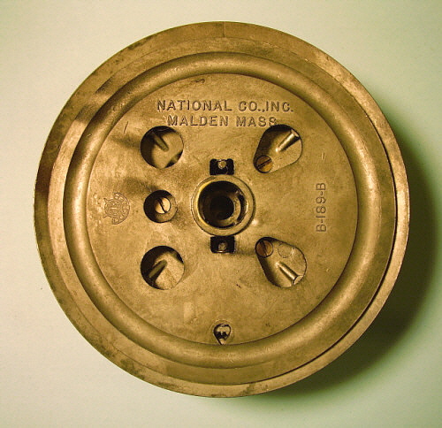
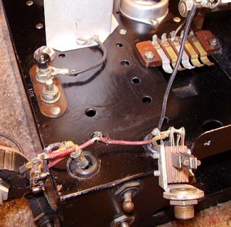
Connections - The schematics were always vague about the plug connections and the wire colors. The cable used a 10 gauge wire, colored red for FIL AC connection to pin 1 of the plug. The cable used an 18 gauge wire, colored blue for B+ connection to pin 2 of the plug. The cable used an 18 gauge wire, colored either green on early cables or yellow on later cables for B- /Chassis connection to pin 3 of the plug. The cable used a 10 gauge wire, colored black for FIL AC connection to pin 4 of the plug.

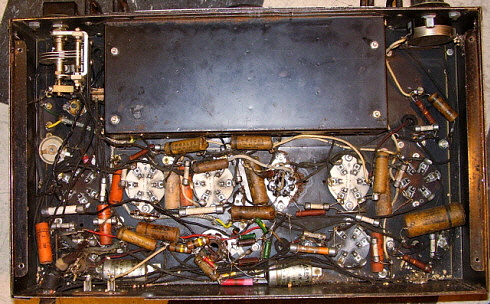
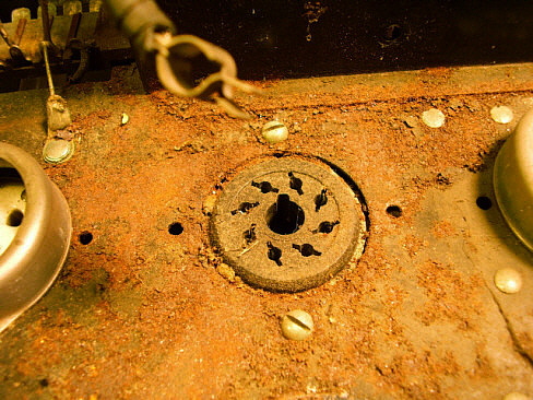
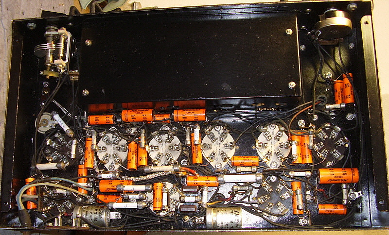
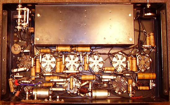
Inside the chassis, the 10 gauge, red wire connects to pin 1 of the BFO tube socket. The 10 gauge, black wire connects to pin 6 of the BFO tube socket. Also, between pins 1 and 6 of the BFO tube socket is connected the wire wound hum reducing resistor. The 18 gauge, blue wire connects to the same tie strip (but not the same terminal) that also provides a ground connection for C28. The 18 gauge, green (or yellow) wire is connected to a chassis ground lug that's mounted at the same tie strip.

Early cables had the B- wire colored green. Later cables had the B- wire colored yellow. 

 
Building a New Power Cable - Even if the original cable is tattered and worn, it is best to keep it since it has the correct current carrying ability for that HRO - but if the restorer wants to replace a missing old cable on a 2.5vac HRO with a NEW cable of the same original length, it will have to be built. The original HRO power cables were about four to five feet in length.

In order to have the new cable be flexible and to have very low resistance you will have to search for proper wire. There are a number of companies that make replica cloth covered wire. Usually this is for vintage lighting but also vintage-looking automotive wire is being produced. You'll need 10 gauge and 18 gauge wires to make the new HRO cable.

The next problem is the outer covering of the repro cable. All of the braiding that I've seen doesn't look vintage and sometimes looks like plastic. There is cloth tape but it never seems to look correct either. Some enthusiasts report the some braided tubular shoe laces can be expanded and used for cloth braiding.  

It's also possible that a special build from one of the antique automobile electrical harness builders could supply an authentic HRO power cable with the correct gauge wires and the proper cloth covering. No doubt an expensive solution.

2.5vac Tubes versus 6.3vac Tubes - The Myth - James Millen wrote, in his monthly QST letter of March 1937, a recommendation that when the HRO was operated on an AC power supply, the 2.5vac tubes should always be used. Millen stated that the 6.3vac tubes produced a noticeable increase in the hum level and noise that would in some cases mask weak signals. In the April 1939 QST letter, Millen recanted what the earlier letter had recommended. Millen stated that the 6.3vac tube quality had improved significantly and there was no longer any advantage to using the 2.5vac tubes. The letter elaborated that a modulated hum around 15MC had been an earlier problem with the 6.3vac tubes. Additionally, the letter mentioned the new Model 697 power supply for the HRO which provided 230vdc B+ and 6.3vac. Also mentioned was the fact that earlier HRO battery operated receivers could not be operated on the new 697 due to the B+ being too high unless the receiver was modified. Some former National employees speculate that the actual reason for continued use of the 2.5vac tubes was due to National being "over-stocked" with power transformers that had the 2.5vac winding which were essentially useless unless used in the HRO power supply.

Unfortunately, many hams and collectors only remember James Millen's original, 1937 remarks. This had led to an "Urban Ham Legend" that the 2.5vac tubes are superior and re-tubing a later HRO Senior with early style tubes will give great performance results. This isn't true. The first problem encountered might be insufficient current carrying ability of the power cable for the 9.5 amps required to operate the 2.5vac tube heaters. It depends on the particular HRO, although most do use the same power cable regardless of the heater voltage. Also, the screen divider was changed for the 6v HRO Senior to provide a slightly lower screen voltage required for the newer manufacture 6C6/6D6 tubes. A somewhat higher screen voltage was used on the old 57/58 tubes and early 6C6/6D6 tubes. The later HRO Senior, with the 6.3vac tube IDs on the chassis, will perform great "tubed" as it came from National. The early HROs that were originally 2.5vac receivers should be operated "as designed" - with the 2.5vac tubes. Although, the early 2.5 vac HRO can be re-tubed to 6.3vac and it will operate okay, you usually can't re-tube a 6.3vac HRO to 2.5vac tubes and expect it to work well without some modifications.

 
Speakers - The HRO normally does not have an audio output transformer installed in the receiver. This was common practice when the HRO was designed. Most manufacturers mounted the audio output transformer on the speaker. This practice does allow full B+ to be present the speaker pin jacks at the receiver - always a source of unnecessary worry for electrophobics. Even the Navy worried so much about the B+ on the speaker pin jacks, they wanted output transformers installed on the HROs that they ordered (all military National receivers, in fact.)  If you don't have the "NC" speaker, or you have the box with a non-original speaker and need an audio output transformer, the HRO output Z is 7000 ohms on the primary (single ended) and the speaker Z is usually 8 ohms. Most universal audio output transformers will have a range on the primary, e.g., 4K to 10K ohms Z and a selectable secondary of 4 or 8 ohms Z. These usually work fine with the HRO.    >>> >>>   Check the DC resistance of the primary, it should be around 150 to 300 ohms but this depends on the power rating of the transformer. Higher power transformers will have larger gauge wire used and therefore a lower DC resistance. You should go by the impedance first and just reference the DC resistance. There are many "universal type" audio output transformers that will work fine with the HRO. The Triad S-53X is an excellent choice (but certainly not the only one,) providing 7K ohm primary with an 8 ohm secondary with the primary DC R at 300 ohms. (Actually, the S-53X is a universal audio output transformer with the option of selecting many different combinations of primary and secondary impedances but a 7000 ohm Z primary and 8 ohm Z secondary are options that are provided.)
 

Modifications - Unfortunately, the HRO and HRO Senior receivers were built during the Depression. This means that many hams - out of economic necessity - had to keep their receivers as long as possible. The temptation to modify a great design was going to be there. Also, during WWII there was a complete absence of parts for those hams who could still operate - the only way to legally operate was as part of the Civil Defense emergency nets that were on usually once a week during WWII (transmitters had to be registered with the Navy to be legally used during that time.) This also led to some modifications out of necessity in keeping the receiver operational. After WWII, cheap HROs were around and subject to more abuse during the "modification mania" of the fifties. Very few pre-WWII HROs are found today that don't have some kind of mods installed. Whether the receiver can be returned to original will require a detailed examination. Unfortunately, many hams drilled holes and cut panels or chassis to install their so-called upgrades. Certainly, the rarity of the HRO will dictate whether the effort is justified to return the great old receiver back to its original design and appearance. Be aware that National performed their own upgrades on receivers that were returned to the factory for repairs or "updating." Usually the caliber of workmanship and the engineering thought process is far superior to that encountered from the average "hamster."   >>>

>>>   Post-WWII production, that is the HRO-5TA1, HRO-7, HRO-50 or HRO-60, are less likely to be found extensively modified. The abundance of surplus gear to modify and the fact that the receivers were new or fairly new seemed to curb "cutting and hacking" activity. Sometimes product detectors will be found installed in the NBFM accessory socket of the HRO-50/60 but these are normally homebuilt and based on an article that was published in CQ magazine in the mid-sixties (later in Electric Radio.) The problem with the HRO-50/60 product detector plug-in mod is that the BFO is normally disabled when in NBFM and the stock National switch is a special build that doesn't provide a terminal to actuate the BFO when in NBFM. A separate BFO switch is necessary although some mods have the BFO wired to be "on" all the time - okay for CW and SSB (the main concern at the time) but a problem if AM reception is desired. These mods are easy to remove and return the circuit to an original configuration. Operation today using the HRO-50/60 is normally for vintage AM nets and the need for a product detector is nil. However, if CW or SSB operation is desired using a stock HRO-50/60, just reduce the RF Gain and increase the AF Gain for the proper ratio of signal to BFO injection at the second detector - that's the way it was done before product detectors came along.
 

HRO Restorations in Detail   
The following articles detail the restoration of a few HRO receivers. Each project has various techniques involved in the rework of some type of damage that is found from time to time, not only in HRO receivers, but in others types of equipment as well. Hopefully each Restoration Article will have some helpful information for restoring HRO receivers.

1935 HRO Receiver SN H-103 - Restoration

To the right is a photo of HRO sn H-103 taken when the receiver was first obtained (around 2007.) It is obvious that the cosmetics were in very good condition. The yellow "R-014-8" designation may have been an identification for commercial use but nothing was documented as to its meaning or of the receiver's former use. Most of the problems with H-103 were under the chassis. Foremost was the 1.25" hole that had been punched in the front left section of the chassis. This was going to be a challenge to repair. Also, the receiver had been totally re-capped using modern-style yellow plastic capacitors. Additionally, there were some non-original resistors, a few modifications with some extra non-original parts installed.

The goal in the restoration was to bring H-103 back to full operation using the original design circuit and using parts that would have the appearance of the originals but were rebuilt new parts. The most time consuming part of this kind of restoration is restuffing the paper-wax capacitors. Since I didn't have the original caps, I ended up robbing a complete set of HRO "Sprague" paper-wax capacitors from an old HRO parts set.  NOTE: Run-G HRO receivers probably used Micamold paper caps but these are difficult to find so I used Sprague which were used in all post-1935 HRO receivers.   These caps were restuffed using modern "yellow jacket" caps installed into the original paper-wax shells. The shell ends were then sealed with colored wax. Proper orientation was maintained though this was for aesthetics only. While this is sometimes tedious work, the end results are a receiver that looks totally original and performs as new. Photo right: HRO SN H-103 before restoration

Below is a "before" photo of the underside of the chassis showing all of the non-original type capacitors along with other non-original parts and circuit modifications.

Below is an "after" photo of the completed restoration of the underside of the chassis showing how restuffing caps preserves the original appearance.

Another challenge were the white ceramic resistors with lead end-caps that National used in the HRO receivers up to about mid-1936. I had to "recreate" three of these resistors to replace modern resistors that had been installed. I checked the parts boxes and found three correct size lead end-cap resistors. Of course, they weren't the correct value but all we needed were the lead end-caps to build our replicas. Next, I needed to find correct value, IRC (International Resistance Corp.)1/2 Watt Carbon resistors from the late thirties. These resistors are the correct physical size to fit into the lead end-caps. The lead end-caps will just "twist off" of the old resistors and then, by drilling a 1/16" hole, the lead end-caps can be fit onto the new resistor (with the leads protruding through the holes.) Soldering secures good electrical contact to the lead ends. All that remains is to paint the body white and install the resistor replica. Originally, the ceramic resistors were lettered by hand or stamped with the value, however it looks better to just leave the body white as nothing looks quite "correct" or "original" for putting the value on the resistor. The photo to the right shows one of the replicas installed next to a rebuilt (restuffed) paper-wax capacitor.

This photo shows the aluminum hole plug installed but not painted. Also note that the plastic cap is missing from the push-type "ANT" post.

The 1.25" hole punched in the front-left part of the chassis was a real problem. It appears that someone wanted to install yet another mod into the receiver but fortunately stopped after they had done this damage. The hole was so large an epoxy fill would not have had enough strength. I decided to make a "custom-fit" plug and epoxy it in place. The plug was made out of .050" aluminum since this was about the thickness of the chassis steel.  The rim interface would be filled, sanded and then painted to match.

After the plug was fit and the interface filled, the paint matching was attempted. Since this was a rather large area, artist's acrylic would be too flat of a finish to match. The photo to the right shows one of the "black" paints used that was a fair match. Several "black" paints were tried but the best match came from Testor's Jet Black, plastic model paint that comes in the little glass jars at hobby stores. See the chassis photo below for the final appearance. Though not perfect by any comparisons, I think the fix is better than the gaping hole.

On most HRO receivers, the gear box has probably never been opened since the receiver left National. The grease is usually dried up, the anti-backlash split-gears are tight and the other bearings also need lubricant.

I thoroughly cleaned the old grease out, then used "3 in 1" oil on the split-gears to assure that they can move freely, which eliminates backlash. I used "Lubriplate" for grease application - I don't use Lubriplate anymore since it tends to dry up after a while. I use any light-weight multi-purpose grease. The worm gear might also need to be removed and lubricated if the gear box is particularly dry but most of the time the worm gear can be lubed with oil drops to the end bearing in the housing and by working grease to the worm gear by lubing the split-gear. The rotor contacts on the tuning condenser should be sprayed lightly with a contact cleaner that has some lubricating qualities. When installing the micrometer dial, notice that the elliptic rides on the boss of the tuning shaft bearing housing. I usually find that this area is entirely devoid of lubricant which results in a "rough" feel or noisy operation of the micrometer dial. I lightly grease this boss before installing the micrometer dial.

All of the tube sockets should be cleaned. I usually spray De-Oxit on the pins of the tube before inserting it into the socket a few times. I also clean the grid caps as they are always oxidized. On the HRO, you also have to clean the flex finger contacts for the coil sets. These are usually very dirty and if not clean will compromise the all-important contact with each coil in the coil set.  After a good set of tubes are installed, all that remained was test and alignment. There were several circuit modifications that I had to remove on this HRO and then return the circuit to original. Testing was going to reveal whether I did this correctly or not. Fortunately, everything worked pretty much as it was supposed to. During test, the receiver's gain was up and down a lot so I removed the tubes and cleaned the sockets again which corrected that problem.

The S-meter seemed to be far too sensitive and the adjustment pot had little effect. The problem was the R10, the screen load resistor (which is part of the S-meter bridge,) was only about 8K and the correct value should have been 20K. So, another lead end-cap resistor replica was made to replace R10. All resistors were checked during the rebuild but I obviously missed the low value R10 - at least it showed up as a genuine problem during test. With R10 at 20K the S-meter circuit worked correctly and the S-meter responded to signals in normal manner. Early HRO receivers usually have R10 at 30K. Later receivers went to 15K. 20K seemed a good compromise.

The next step was alignment of the IF, which is straight forward although the IF frequency is determined by the actual crystal frequency - in this case 456.5KC. After the IF is aligned, each coil set has to be aligned for proper tracking. Most HRO receivers don't have all of their original coil sets anymore. H-103 was no exception, having only a 40M coil set with it. We usually have to rely on "orphan" coils to make up a complete set of coils for each HRO receiver. These "orphan" coils must first be disassembled, cleaned and inspected. Many times dirt, dust, bugs and spider webs, along with broken wires or bent condenser plates will be found in each of the coil boxes. In fact, the 40M coil that came with H-103 had a broken connection inside the 1st RF coil that had to be repaired.    >>>

>>>  After reassembly, the coil set needs to be aligned to the specific receiver that is going to be used with. There is a significant difference between each HRO receiver, especially between the 6.3vac tube type and the earlier 2.5vac tube type. While any coil set will function okay in almost any HRO, the alignment will assure greatest sensitivity, correct tracking and best performance of the receiver. When aligning HRO coil sets, the general coverage must be aligned first and then the bandspread. Switching to bandspread requires relocating four screws on the coil contact insulator blocks. The eight adjustment trimmers are accessed from the top of the chassis through holes just in front of the tuning condenser. It is easier to access these holes if the front-top piece of the cabinet is removed. It is held by the two top screws in each corner and the dial pointer "diamond." If the lower end of the tracking needs to be adjusted, the padders and inductance disks can be accessed through the holes in the back of the coil shields on each coil set. On coil sets A and B, the LO inductance is adjusted with a "loop" of wire inside the coil form that has its relative position moved to change total inductance. Once the coil set is aligned, the final adjustment is to readjust the 1st RF coil trimmer to the station antenna. I happened to also have correct vintage E and F coils for this HRO. The E coil provides tuning of the 160M band along with the upper part of the AM BC band. Coil F covers 480kc to 950kc for the lower part of the AM BC band. These coils do not bandspread. They also have a padder adjustment on the top of the coil set so when aligning, both high-end and low-end tracking can be adjusted from the top access holes. 

The photo to the left is the finished result. Like all fully restored HRO receivers, H-103 is very sensitive and the bandspread capabilities make the amateur bands seem to tune on and on - 400 divisions in fact, or the equivalent of about nine and a half feet of linear dial. The feel of the micrometer dial is smooth and the accuracy of any reset is precise. Audio is very pleasing even though it is just a single-ended 2A5. I am using an early 8" National speaker box with the cloisonné "NC" emblem. Since the HRO receiver originally has no internally mounted audio output transformer, National installed the output transformer in the speaker box.

UPDATE: Dec 2018 - When I did this restoration of H-103 (over ten years ago,) I used modern plastic insulated wires to make a power cable and that cable was covered with brown duct tape. It looked really awful but worked fine. I've acquired several HRO "parts sets" since doing H-103, so I decided to harvest an original power cable from one of the "junkers." The cable was cleaned, an appropriate plug installed (with rubber cover) and the cable installed. H-103 still works fine and now looks very original, even from the rear.

Additionally, I acquired a complete, matching set of coils D, C, B and A from run-P. I decided to replace the "mismatched runs" coil sets I did have with H-103 and use this 1936 sets of coils. I aligned the four coil sets to the receiver without any issues. Although these P-run coil sets weren't originally with H-103, having a matching set of coils (all serial numbers match each other) is the next best thing.


photo left: HRO sn: H103 as it appears nowadays (Dec. 2018)


1940 HRO Senior Receiver  SN 463-K - Restoration
 
The following is an article I wrote in 2006 for use in  "Assembling an Authentic Pre-war Ham Station" that detailed the restoration of my 1940 HRO Senior SN 463-K.
Temporarily deleted - but not lost. Here it is again....

I have had HRO 463-K for over 30 years having purchased it from Fred Winkler, an old radio collector friend of mine, for $40 back in the mid-1980s. I never did much with it except acquire a complete set of coils (it did have the matching C coil with it,) replace some missing tube shields and a general clean-up. I thought back then that the performance wasn't as good as other HRO receivers that I had (and had sold) but I never investigated further. So, the HRO became just part of the pre-war equipment that was on display but not used. A rekindled interest in early HRO receivers prompted me to take another look at this old relic of mine. With a little coaxing the HRO did seem to function. An alignment also seemed to help but generally the receiver didn't have the sensitivity expected and also gain across the band was not consistent.

Taking a closer look into the plug-in coil receiving bay revealed the problem - one of the flexible contact fingers for the mixer section was broken off. This was the ground return for the tuning condenser section contact. Fortunately, I did have a parts set HRO that could provide a replacement for this defective part. The problem was to find where I had stored the HRO parts set. After several hours of moving many heavvvy boxes, I found the HRO parts set stowed behind a six foot tall Navy TAJ-19 transmitter that was in the garage. Though the parts set was missing about half of its parts, it did have the needed finger contact assembly. Replacing the mixer finger contact assembly requires removal of the tuning condenser to gain access to the part. This is an easy task as the HRO was designed for ease of maintenance. Once this problem was repaired I decided to go ahead with a total rebuild of the HRO.

A complete re-cap job was performed on the HRO but rather than just replace capacitors with no regard for under chassis appearance, I decided to re-stuff all of the paper wax caps to preserve the original looks of the assembly.

Performing this type of detailed rework turned up something unusual - a factory miss-wire that was not caught during test and alignment at National. The error was that C9, the bypass cap for the 2nd IF transformer secondary, was connected to the wrong side of R-8 which placed C9 connected directly to the AVC line. Additionally, C9 was only wrapped to the terminal strip - not soldered. Obviously, this was a "transparent" type of problem - one that would not be caught in test because the error would not have affected performance enough to be noticed. Then one also has to take into account that the receiver was used for many years and this problem never noticed - certainly not a major concern but interesting how these sort of errors are found so many years later. When finished with the re-stuffing of the capacitors all resistors were checked for correct value. I usually allow about 25% tolerance but all of the resistors were much better than that. The photo to the right shows the finished result.

As for the top side of the HRO chassis, a thorough cleaning showed that there were a couple of minor rust areas. These were touched up using artist's acrylic that I matched to the exact color of the particular chassis or cabinet. Since every painted piece of an old receiver has aged somewhat differently the colors always require custom matching. Fortunately the areas involved on the HRO were small and touch up not noticeable.

The tuning condenser had to be removed for the mixer finger contact assembly repair so the entire assembly was cleaned and lubed while off the chassis. When the gearbox cover was removed for cleaning and new lubrication it was found that one of the anti-backlash springs had come off of its mounting peg. Just another example of minor problems that turn up while doing a detailed restoration.

The S-meter scale was severely discolored which is typical for plastics of this time period. I happened to have a very nice original Marion Elec. Inst. Co. S-meter that had a nicely colored scale. Although the red was somewhat faded, the overall appearance was a vast improvement over the original meter scale. The cabinet and front panel were in nice shape so only minor touch up was necessary to have everything ready for reassembly.

After installing all of the tested tubes, shields, the front panel and knobs we were ready for alignment. The HRO has an IF frequency of 456kc +/- whatever the exact crystal frequency actually is. This is determined by sweeping the frequency around 456kc using a signal generator with the crystal filter on and listening for the peak that occurs at the exact crystal frequency. In my case, the crystal frequency was 456.3kc and the IF was aligned to that frequency using the S-meter as an output indicator.

After the IF alignment, it is necessary to begin aligning each of the coil sets. You have to start with the general coverage section first then proceed to the bandspread section. Switching from general coverage to bandspread requires moving four flat head screws located on each of the molded contact pin sections on each coil. The graphs give the micrometer readout to frequency relationship and usually all that is necessary is to trim up the adjustments on top of the coils. These are accessible from the top of the chassis through the eight holes just in front of the tuning condenser mount. I use a long shaft blade screw driver with the shaft taped to prevent shorts against the cabinet or tuning condenser spacers.

If the gain is not reasonably even over the entire range in the bandspread mode, the back padders need to be adjusted at the low end of the scale. Though there are access holes that make it possible to adjust the inductance disks (general coverage) or padders (bandspread) while the coil set is installed in the receiver, it isn't recommended. It's easier to just remove the coil set, make an adjustment and then install the coil set and check. After the alignment is complete, you still have to adjust the 1st RF coil in each coil set to the particular antenna that is to be used. Since there is no antenna trimmer, this has to be done for best response at the normal operating frequency with the antenna that is normally used. The photo to the left shows the completed 1940 HRO Senior, SN 463-K.
 

UPDATE: 2018 - It's been over ten years since I restored 463-K. Over those years I was able to find several orphan coil sets to end up with eight coil sets for 463-K. Low Frequency coil sets G and H provide coverage from 100kc up to 430kc. Coil sets E and F cover from 480kc up to around 2mc. Coil sets D, C (the only "original-matching" coil set,) B and A are the standard coils sets providing coverage up to 30mc. All eight coil sets were aligned specifically to K-463 and this has resulted in the receiver being a very consistent performer. It always seems to operate fine even if it hasn't been powered up in a year or two. 

CONTINUE TO PART 4


HRO Part 1                       HRO Part 2                      Return to Home Index


Radio Boulevard
Western Historic Radio Museum

 Vintage Radio Communication Equipment Rebuilding & Restoration Articles,

 Vintage Radio History and WHRM Radio Photo Galleries

1909 - 1969

- 60 years of Radio Technology -


This website created and maintained by: Henry Rogers - Radio Boulevard, Western Historic Radio Museum © 1997/2023