July 22, 2021 - This
next observation was me finally realizing that the receiver had a few
problems. When listening in MCW
(Modulated CW) and AUTO (AGC on) mode for AM transmissions the bandwidth is very broad as would be
expected with a TRF receiver operating with AGC. SW-BC stations in the 49M band (late
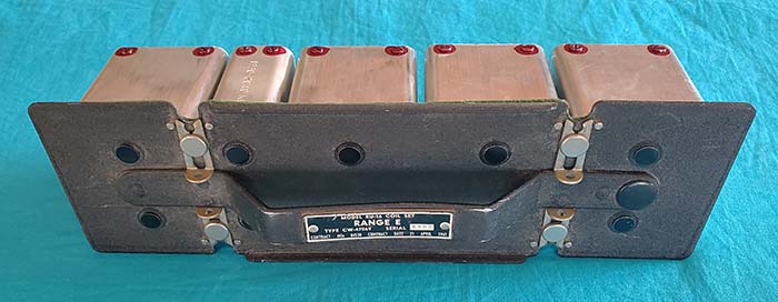
afternoon,) were quite broad, especially the strongest stations. AM-BC (using the E-Range coil) in AUTO
results is many of the stations over-lapping when using a large antenna.
The AGC does keep all signals at the same output level and the OUTPUT
control has to be set to minimum and even then the signals are too loud. NOTE: AGC wasn't
functional at this time and the RF amplifiers were running a full gain
which resulted in the broad bandwidth.
|
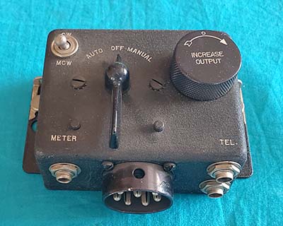
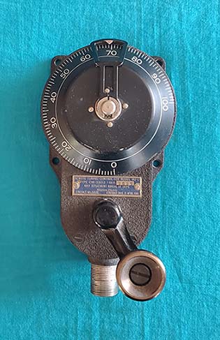
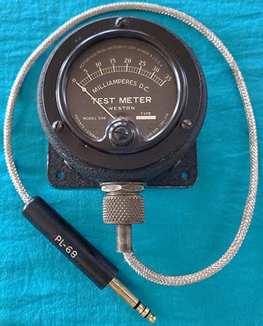
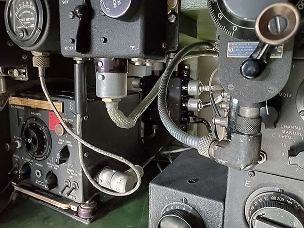
Type-22266 Test Meter Reveals AGC Problems - August 1, 2021
- I was able to find a CBY-22266 Test Meter that cleaned up nicely and
did function correctly. I installed the meter plug into the meter jack on the Receiver
Switch Box. When tuning in signals in AUTO there was no deviation in a meter reading of about
24mA. I switched to MANUAL and could adjust the Test Meter current with
the OUTPUT control. However, all signals are loud in AUTO and the Test
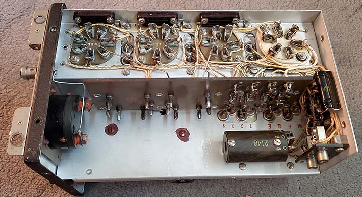
Meter current doesn't change which indicates the AGC isn't working. The type-77 AGC tube tests good. To be able to access test points within the
circuit requires that the receiver be out of its case. All resistors
check within tolerance except #31 and #24 but these resistors measure
much lower than their marked value which usually indicates a parallel path and
not an out-of-tolerance resistor. NOTE: Just to verify, #31
and #24 were isolated and tested,...of course, they were well-within
spec. Further testing requires that the
receiver be powered-up out of its case. I'm not too sure how stable the
receiver will be without the shielding the case provides but for DC
voltage measurements it shouldn't matter.
With the receiver in operation in AUTO, voltage at the grid of the AGC
77 tube is -76vdc and the bias voltage from the dynamotor measures
-89vdc. The grid bias voltage at the RF amplifier tubes is about
-1.5vdc in AUTO and doesn't change with various signal input levels. The grid bias voltage is insufficient for
cut-off of the RF amplifier tubes and therefore, since the cathodes are
grounded in AGC mode, the RF amplifier section is running at full gain.
A DCR test of the RF amp cathodes confirms that, in AUTO, the cathodes
are grounded through the correct value cathode resistors and, when in
MANUAL, the INCREASE LEVEL pot is connected from RF amp cathodes to
ground. The problem appears to be that the AGC tube doesn't develop the DC
voltage since even on the AGC-side of the RF grid resistors, the bias
voltage only is about -1.5vdc. The RF grid bias voltage should be around
-7.0 for complete cut-off (with +250vdc plate voltage.) Since the signal from the RF amplifiers is
coupled through a capacitor to the AGC tube, that capacitor could be
open (it's okay.) It's also possible that the DC filters on the output of the AGC
line are not working (yep!) I need to check alignment of 59C since
this trimmer adjusts the input RF resonance to the AGC tube and to the
Detector. The trimmer does have "undisturbed" GLPT but that adjustment
was last made 80 years ago. I doubt this is a problem because the
receiver works great in MANUAL (GLPT'd adjustment was okay.) The problem is probably a leaky capacitor in
the AGC DC filter which would load-down the AGC/RF grid bias voltage. Partial
isolation is the easiest method to find the bad component. Although a DMM
can't measure capacitor leakage accurately, if the meter shows some DC
resistance, you can be pretty sure the capacitor is bad. The two filters
in the AGC circuit use #218A & B and #4A and B. The DMM didn't show any
DCR on #4A/B but read about 10K on #218A & B (#218 is a triple .5uf 100vdc
with common ground.) I substituted externally connected capacitors which
got the AGC producing RF grid bias voltage and Test Meter reacted as
expected with the cathode current reading about 24mA with no signal and
reading about 9mA with a strong signal from the RF sig gen. However, the
output level can't be adjusted so it seems that the audio output pot is
not working (direct DCR measurement of the pot confirmed that it is
functioning correctly so this problem is probably also leaky capacitor
related.) |
|
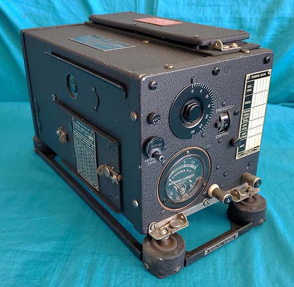
Problem Assessment -
Generally, paper-dielectric capacitors were never expected to survive as
usable components over an eighty year time period. There were a few
exceptions such as oil-filled types or paper dielectric capacitors built
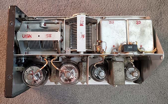
with oil-impregnated paper. However, the tub capacitors
in the RU-16 receiver are just the average paper-dielectric types that
are potted
in bee's wax and this results in an average finite life-expectancy. It
seems that all six 0.5uf capacitors exhibit significant leakage current
that is affecting performance. There are also sixteen 0.1uf 400vdc
capacitors that comprise the eight dual 0.1uf tub capacitors. These
capacitors don't seem to show significant leakage but they certainly wouldn't pass a true leakage test (series
resistance) using a LCR-Z-bridge. In fact, when rebuilding these tubs
I found that several had corrosion on the inside indicating
contamination that happened during the original construction of the
capacitor. One 0.1uf dual capacitor was green on
one end with corrosion, so it definitely was necessary to rebuild all
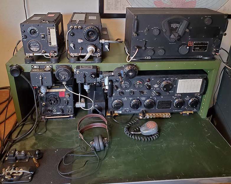
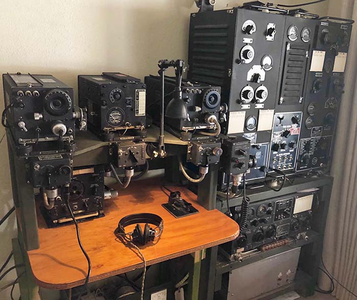
of the tub capacitors. Since I plan on using the RU-16 "on the
air" in a vintage military radio station setup, I would want to have the
receiver performing at its best. Unfortunately, I think that will
require replacing all of the paper-dielectric caps - yep! All of the
paper-dielectric caps are
mounted in metal tubs. To maintain as much physical originality as possible, I'll
have to rebuild all of the tub capacitors using new polyfilm caps that will be
mounted inside the original tubs. |
|
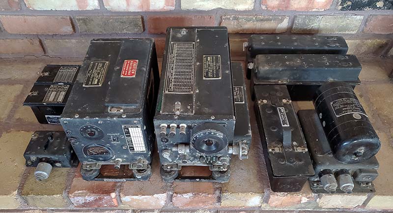
Rebuilding Tub
Capacitors |
Tub #3562 (Qty 1) - contains three 0.5uf 100vdc caps in tall tub with
terminals on the bottom
Tub #1575 (Qty 1) - contains two 0.5uf 300vdc caps in tall tub with
terminals on the bottom
Tub #1573 (Qty 1) - contains one 0.5uf 300vdc cap in short tub with
terminals on the bottom
Tub #1572 (Qty 5) - contains two 0.1uf 400vdc caps in short tub with
terminals on top
Tub #1574 (Qty 3) - contains two 0.1uf 400vdc caps in short tub with the
terminals on the bottom
Total of 11 tubs to rebuild |
Polyfilm Capacitors Required
0.5uf @ 100wvdc - Qty: 3 - Note: actually used 200vdc caps due to tub
size vs capacitor size. Had to order the caps.
0.5uf @ 300wvdc - Qty: 3 - Note: actually used 400vdc caps. Had caps on hand.
Tight fit on #1573 due to small size of tub.
0.1uf @ 400wvdc - Qty:16 - Note: used 400vdc caps. Had caps on hand.
Total of 22 capacitors needed |
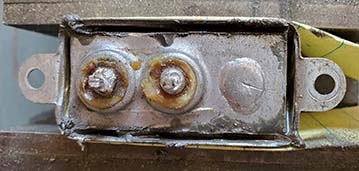
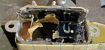
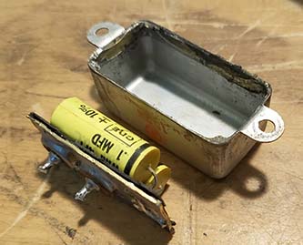
Tub Rebuilding Technique - Once a
tub is disconnected and dismounted it's then clamped in a small bench
vise with the "soldered in place" top or bottom facing up. With a Dremel
tool with a 1.5" diameter cut-off disk installed (E-Z Lock type,) I make a slice
that's right next to the inside edge of the tub on the soldered seam. I had to do one slice and then rotate the tub
to make another slice, then rotate and slice again until I had worked my
way around the soldered seam of the bottom. There were very small
connective metal pieces at some of the corners since the cut-off wheel
sometimes didn't allow going
all the way to the edge. These connective metal pieces can be easily cut with
small wire cutters. I used a small blade screw driver to pry
up the bottom piece (easy to do) enough to see the connecting wires that
need to be cut
with small wire cutters. There's also a common ground wire that needs to be cut.
Now the bottom cover with the terminals can be completely dismounted.
Inside there's a black fiber cover that the capacitor wires were routed
through. The fiber cover can be pried off
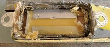
easily. Now, the rest of the tub has some bee's wax and the capacitors
inside. I used a
hand-held heat gun to melt the wax out of the tub. The capacitors can
be removed with needle nose pliers or pried out with a small blade
screwdriver. If carefully done, the paper
liner inside the tub will not be damaged and can be left inside for
insulation. On the smaller "short tubs" the paper can't be saved
because it's wrapped around the capacitor body but the paper
really isn't necessary anyway. I used the heat gun to get the residual bee's wax off of the
bottom plate too. Also, I cleaned the residual wax off of the mica insulators
on the terminals.
Next, the new capacitors are connected to have one common lead with two or three
"hot" leads that are connected to the terminals
of the bottom. I used just the
capacitor leads to make the connections to the tub (common) and to the
terminals. I used small sleeving on all the "hot" leads to have the
capacitors well insulated. Since the commons are connected to the tub,
those leads weren't sleeved. The terminals have a central hole through
which the wire leads were inserted and then soldered. The old wire can be
removed from the terminals by heating the terminal to melt the solder
and then pull the old wire out. Then the hole can be "chased" using a
#60 drill bit held in a pin vise. The terminal insulators should be
checked for any solder bridges or other potential problems and again
cleaned with alcohol. There's a hole in the bottom metal
plate for the common wire to be soldered. I pre-test the new capacitors
for value and then proceed with the installation. The capacitor assembly
has the "hot" leads run through the hole in each terminal and then
the leads are clipped and soldered. The common lead is routed out the hole in the bottom
plate. Next, install the capacitor assembly into the tub. Check to be sure
that the "hot" leads can't short against anything (make sure the "hot" leads
are sleeved and as short as possible.) I don't put any filler (bee's
wax, silicon caulk, hot-melt glue, etc.) back in the tub, just the
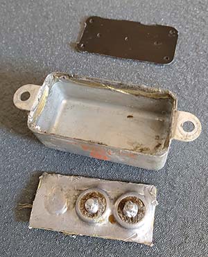
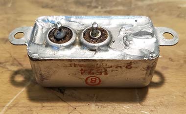
capacitors and fiberboard insulators. With the bottom plate in place, I next had to
solder one or two corners of the plate to the tub to make sure the
bottom plate was straight and at the proper height which is just below
the rim of the bottom of the tub. Also, I had to make sure the common wire
was soldered into the seam soldering. I used a 250W Weller soldering gun
which was hot enough to allow a smooth bead of solder to be "flowed" around the
perimeter of the bottom to seal the tub. Once the tub has cooled a little,
the terminals can be checked for the proper value of capacitance with
reference to the common tub body. The tub was cleaned with denatured
alcohol. Try to be careful in cleaning and handling of the tubs in order
to avoid damaging the red paint-stamped nomenclature (the red
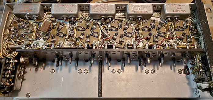
nomenclature suffers a lot during the rebuilding process.) Then the tub is remounted into the
receiver and wired into the circuit. Originally, there was a coating of
bee's wax on the terminals that probably was "dripped" on after the
wires were installed (the wax actually looks and behaves like
light-brown sealing wax.) Rebuild time per
capacitor tub is about one hour from starting the removal from the
receiver to completing the reinstallation back into the receiver.
Photos below show the tub rebuild process on a #1574 dual 0.1uf
400vdc capacitor. The other types of tubs used in the RU-16 were rebuilt
using the same procedure with slight variations. Tubs #1572 have the
terminals on the top of the tub and the bottom plate is just a flat
cover soldered in place. These are easier to rebuild since the new caps
can be fit into the tub, soldered to the terminals, etc. and all
that's left is to install the bottom plate. Tubs #3562, #1573 and #1575
use 0.5uf capacitors that are fairly large but 400vdc types will fit
into the tubs, with the exception of #3562 which must use 200vdc types. Tub #1573 is a very tight fit
using a 0.5uf 400vdc cap but it will fit in although I did have to use an
insulating piece of fiber board on the bottom plate since it was right
up against the capacitor body. |