Radio Boulevard
Western Historic Radio Museum
 

Shipboard Radio Receiving Equipment
1918 up to 1927

PART ONE
 

1.  SE-143 - Navy Department - Bureau of Steam Engineering - National Electrical Supply Co.(NESCO)
2.  SE-1387 - Navy Department - Bureau of Engineering - National Electrical Supply Co.(NESCO)
3.  SE-1834 - Navy Department - Bureau of Engineering - National Electrical Supply Co.(NESCO)
 

Histories, Circuit Designs, Operation

Restorations of SE-143, SE-1387, SE-1834

Performance Testing with Reception Logs

Equipment in Part Two - SE-1420, IP-501, IP-501-A, IP-503

by: Henry Rogers - Radio Boulevard-Western Historic Radio Museum


Navy Shipboard Radio Room  ca. 1925
SE-143 Receiver with Various "Upgrades"
The ship's Captain awaits an important message

According to RCA, the 1918 SE-143 was the first radio receiver available that performed adequately and was able to receive all types of signals whether they were from Spark Transmitters, Arc Transmitters, Alexanderson Alternators or from Vacuum Tube CW Oscillators. Surprisingly, RCA supplied manuals for the SE-143 as late as 1936. But, how could a WWI RF Tuner be in use onboard ships years after it should have been obsolete? UPGRADES! The SE-1387 and the impressive SE-1834 were especially designed, in 1922, to be used with the SE-143 (and similar Receivers) to upgrade this WWI RF Tuner into a seven-tube TRF receiver with three broadband RF amplifiers, a detector, a tunable heterodyne oscillator for CW and two-stages of audio amplification. All accomplished externally with no modifications necessary other than wire-connecting these two devices to the already existing SE-143 terminals. The following examples of WWI and 1920s electro-technology illustrate how incredibly fast radio circuit designs and vacuum tube evolution were improving the communications equipment being built for commercial and military use.


Navy S.E.143 - U.S. Navy - Bureau of Steam Engineering
National Electrical Supply Company (NESCO)
SN:848N  Date on ID Plate - 1918

U.S. Navy - Bureau of Steam Engineering

S.E.143 - Short Wave Receiver - SN:848N - 1918 Contract

National Electrical Supply Co. - Washington, D.C. - NESCO


The S.E.143
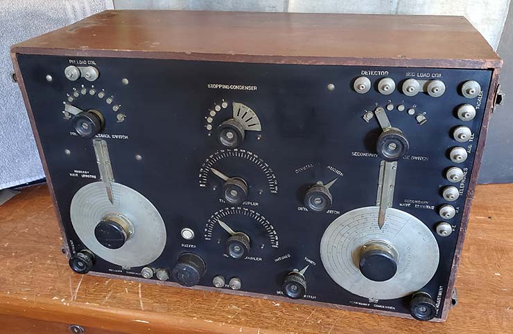
was a WWI Receiver that was essentially an RF Tuner (hereafter referred to as SE-143) It was used extensively by the Navy in the post-WWI era from 1918 up into the late-1920s (manuals for the SE-143 were available from RCA as late as 1936.) Other versions, like the IP-500 (usually built by Wireless Specialty Apparatus Co.,) were used on commercially-owned ships. The SE-143 was a sophisticated RF Tuner that provided a series LC Primary tuner and a parallel LC Secondary tuner. The Coupling coil between the Primary LC and the Secondary LC could be varied 90º and actually moved the coil from the control using bell-crank levers. An adjustable position Tickler coil (for VT detectors) was located inside the secondary coil form directly under a series-connected Secondary Coil extension to promote better feedback. The front panel TICKLER COUPLER control used a bell-crank lever control to rotate the Tickler coil 90º for regenerative feedback. There is also a large untuned additional Secondary coil mounted next to the main Secondary coil. The untuned secondary coil was to provide a broad response for tuning with external Crystal detectors or for finding stations transmitting on an unknown wavelength when using a VT detector. Only the Primary LC is used for tuning in "UNTUNED." When searching for unknown stations, the Coupling was set to MAX for the strongest signal albeit not a very selective response. Once the station was found, then the SE-143 could be switched back to "TUNED" allowing the receiver to be further adjusted (both the Primary and Secondary LCs) for the maximum signal level and best selectivity. Additionally, as the wavelength is decreased (higher frequencies,) the unneeded secondary coil sections are switched out (indicated on the schematic at 48-49 and 41-42.) The Primary Inductance also has switches to disconnect unneeded sections as the wavelength is changed (indicated on the schematic at 26-27 and 17-18.)

To allow the SE-143 to tune to VLF, a Secondary Loading Coil, a Primary Loading Coil and a Tickler Loading Coil could be connected using the front panel terminals so marked. The SE-143 didn't have an onboard detector or an onboard audio amplifier,...it was an RF tuner only. The VT detector was originally provided by the Audion Control Box that was designated as the SE-1071. It provided just one tube that operated as a regenerative detector for the SE-143. There was a two-stage audio amplifier available, the SE-1000 that could also be added. If the SE-143 was operated with an external regenerative detector tube, the SE-143 internally provided the "Tickler" coil (an untuned, adjustable rotational-position coil located inside the Secondary coil) connection since the regeneration function had to provide an in-phase EM field in close proximity to the secondary coil for sufficient feedback. The crystal detector function was mainly provided for emergency situations and its inclusion into the design was a stipulation of Navy regulations.

Ambiguous Tuning Range Specs Explained - The SE-143 tuning range is typically shown as 250M to 6400M (1200kc down to 47kc.) The Secondary Condenser tuning dial agrees with the 250M to 6400M range. However, the actual data plate on SN:848N indicates a tuning range of 250M to 3000M (1200kc down to 100kc.) Interestingly, the 1936 RCA SE-143 manual indicates 300M to 3200M tuning coverage (1000kc down to 95kc.) These ambiguous tuning range specifications might have been the result of the difficulty involved with adjusting the SE-143 to easily and reliably tune its full range due to the seemly insufficient Primary LC tuning range. But, with an experienced radio operator setting up the receiver, the lower end of the Primary LC tuning range can easily extend to 6400M. Usually, if the stock Primary LC versus antenna hook-up is used, the longest wavelengths can't be tuned to resonance or "peak" response using the Primary LC tuning. George Sterling's "The Radio Manual" indicates the 250M to 6400M tuning range and continues on (in the Loading Coils section) to explain how to easily and externally change the Primary Condenser connection from the standard series LC to a parallel LC connection. The series LC presents an extremely low impedance at resonance plus a low XL (inductive reactance) that becomes "non-tunable" at very low frequencies. The parallel LC would present an infinitely high impedance at resonance allowing the LC to tune very low frequencies. Although Sterling's Radio Manual information is for extending the longer wavelength end of the tuning range to function with LF loading coils, the parallel connection of the Primary LC will allow the longer wavelengths between 3000M and 6400M to be easily tuned. The procedure for parallel connecting the Primary LC is simple. Just leave the PRI LOAD shunt strap in place and connect the antenna lead wire to the left terminal of the PRI LOAD. Then jumper the ANT to GR terminals with the GR terminal remaining grounded. Now the Primary LC is parallel tuned and will readily resonate at longer wavelengths.


from George Sterling's "The Radio Manual" 1st Edition - 1928

Series versus Parallel Tuning for the Primary LC - Tuning the Secondary LC to 6400M is easily accomplished but not with the stock connections to the Primary LC. In fact, it will be impossible if series tuning is used on the Primary LC. I've tested the standard series LC and the parallel LC for a comparison when using a 250' wire antenna with the secondary LC tuned to WWVB on 5000M (60kc.) The difference is significant. Since the Primary LC can actually be "tuned to resonance" in parallel the increase in signal level is tremendous, at least when tuning WWVB (which is a strong signal anyway.) When tuning the longer wavelengths, starting by about 3000M or 100kc, the inability of the Primary LC to tune the antenna will be noticed and you won't be able to find a "peak" response. If that's the case, the change the antenna hook-up so that the Primary LC is parallel tuned. Now, finding resonance or "peak" response should be easy.

I've found that with careful set up, using the SE-143 with the SE-1387 and the SE-1834 (these units are covered in their own section further down this article) I can easily and consistently receive WWVB on 5000M or 60kc (over the air) using a 250' end-fed wire antenna. It's a very strong signal if the Primary LC is parallel tuned to resonance. Using an HP3312A function generator set to 47kc with the output connected to a 50' wire laying on the floor and the SE-143 setup using the outdoor 250' wire antenna, I can actually receive that type of signal on the SE-143 set to 6400M or 47kc with the SE-1387 providing the heterodyne for easy detection (47kc is the absolute lowest tunable frequency possible since it's at the maximum C-setting on the Secondary Condenser dial when on Position 6, the maximum secondary L,...to tune lower in frequency requires Loading Coils.) At the other end of the range, 280M or 1060kc (AM-BC KFOY in Sparks, Nevada) is easily tuned. With careful set up on Position 1 and a series Primary LC connection, I can just begin to hear KCMY Carson City AM-BC station, a strong signal on 1300kc or about 225M (KCMY couldn't be tuned to "resonance" but the broad nature of the signal allowed detecting its lower sideband since it's a 10KW station located about 20 miles distance.) If there was a local AM-BC station on 1200kc or 250M, I'm sure it would be easily tuned in. To test 250M reception (for my location) required using the HP3312A set to 1200kc. As a "marker" signal, 1200kc was easily tuned to resonance. The confirmed actual full tuning range of SE-143 SN:848N is 47kc up to 1200kc or 6400M to 250M,...BUT, in actual tuned "over the air" signals received, the longest wavelength signal I can fully tune to resonance is WWVB 60kc or 5000 meters and the highest frequency "fully tuned" signal would be KFOY 1060kc or 280 meters. The longest wavelength limit to the tuning range is only possible IF the user is willing to switch the Primary LC from series to parallel as needed on longer wavelengths. Sterling's Radio Manual shows a DPDT switch arrangement to accomplish the series-parallel change but just moving the wires is pretty easy to do. NOTE: Using LW Loading Coils with a Regenerative Detector and 2-Stage Audio Amplifier, I can tune the SE-143 (plus LW Loading Coils) below 20kc to receive NWC 19.8kc USN MSK Sub-Comm station in Exmouth, Australia. Using SE-143 SN:848N I've been able to tune and receive stations from 1300kc down to 19.8kc, or 225M to 15,000M.

What the Specific Controls Do - The Primary Condenser dial has a 180º scale for half of the dial and linear scales for notations on the other half. The Secondary Condenser is calibrated in wavelength and also has the "letter designations" that were used during WWI and somewhat after as specifying important wavelengths (or frequencies.) Wavelength scaling is the figure shown times 100. A logging scale is also included in the other half of the dial. The inductance switches have letter designations on the Primary LC and numbers on the Secondary LC. The scales for the TICKLER COUPLER and the INDUCTIVE COUPLER are 0 to 180 with a MIN and MAX indication at each end. The scales imply the degrees of rotation for the specific coil. The BUZZER was used as a "potent" signal generator to be used when trying to find a sensitive spot on a crystal detector. The typical battery voltage for the BUZZER is no more than 2vdc if the buzzer is in good condition and adjusted correctly. There's spark gap between the ANT and GND terminals to provide a method to dissipate static charges on the antenna (common problem at sea or in windy areas.) Two sets of terminals are for LW loading coils that, when connected, allow the SE-143 to tune lower than it's 6400 meters (47kc) lower tuning limit. Additionally, a Tickler Loading Coil could be added in series with the internal Tickler Coil by using the front panel TICKLER terminals. Various types of loading coils could be used (see vintage shipboard photo further down showing a DeForest Duo-lateral LW coil apparatus being used for VLF frequencies.) The DETECTOR terminals were provided for connecting the Crystal Detector. If a Crystal Detector is used, then the STOPPING CONDENSER control can be used to select five capacitance values that are connected across the TELEPHONES terminals when DETECTOR SWITCH is set to CRYSTAL. The various capacitors were necessary to bypass any RF existing after the crystal detection. Generally, this would improve the audio response of the 'phones. The STOPPING CONDENSER isn't necessary in a VT detector and it isn't in the circuit when AUDION is selected. The eight vertically aligned terminals allow mating the SE-143 to the SE-1071 Audion Control Box. However, it's not specifically necessary to use the SE-1071. The terminals provide connections to the TICKLER COIL, AUD TEL, TELEPHONES (for Crystal Detector) and the receiver secondary LC outputs RA (grid-audion) and RE (filament-return.) The SECONDARY SWITCH allows selecting TUNED or UNTUNED with the latter routing the SECONDARY  LC to an untuned coil that's closely coupled to the secondary inductance for a broad frequency response for easier tuning when using a Crystal Detector (it can also be used with an Audion detector when searching for unknown stations.) The actual "tuning" is performed using the PRIMARY CONDENSER since the secondary is "untuned." This allows the user to tune the antenna-primary circuit to allow a stronger response for the crystal detector. Then switching to "TUNED" switches out the untuned coil and allows using the SECONDARY CONDENSER to further "peak" the signal response. As mentioned, this process can also be used with an Audion detector when searching for weak or unknown stations.

Set up for Selectable Alternate VT Detectors - The DETECTOR SWITCH routes the secondary LC as necessary for either CRYSTAL or for AUDION. It's possible to use the CRYSTAL position of the DETECTOR switch to connect to an alternate type of VT detector rather than a crystal detector. By using terminal TEL (#75) to access the RA terminal and DET (#81) terminal to access the RE terminal when the DETECTOR switch is placed in CRYSTAL, now the Secondary LC can be connected into an alternate type of VT detector. This hook-up of the CRYSTAL position was used later (in the early-1920s) when external RF amplifiers, heterodyne oscillators operating with non-regenerative detectors and audio amplifier stages became available. With this ability to have two selectable types of signal processing available using different types of VT detector circuits, the radio operator could, depending on receiving conditions, select a regenerative detector utilizing the TICKLER coil in the circuit, or he could select a circuit that provided RF amplifiers, non-regenerative detector, a heterodyne oscillator (for CW reception) and audio amplifiers. The radio operator would still have a crystal detector somewhere in the radio room and be able to connect it to the SE-143 if there was an emergency since this was part of Navy and Maritime regulations.


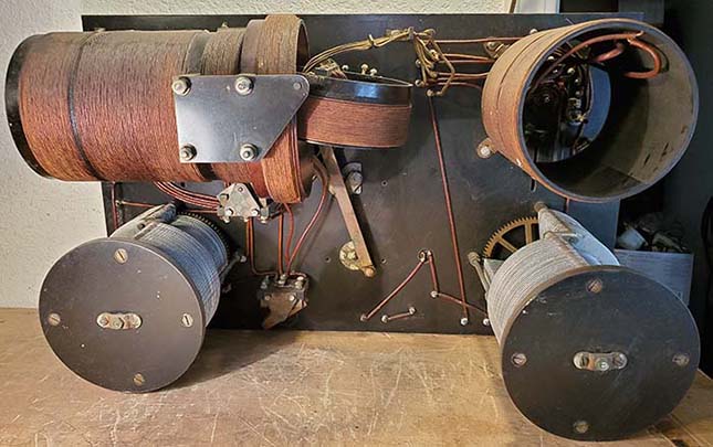
SE-143 Inside - RF Tuner only. Signal detection and amplification were external functions.


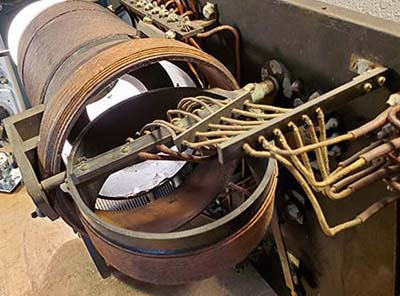
Close-up of the Secondary Inductors. Foremost is the Primary to Secondary Coupling Coil that can rotate 90º. Then the fixed-position, Untuned Inductor for Xtal set-ups or finding unknown stations (Coupling Coil must be set to Maximum coupling for strongest signal response.) Inside the Main Secondary Inductor the Tickler Coil can be seen. The Tickler Coil rotates 90º to provide adjustable regeneration with an external VT detector. Note that there is a series secondary coil directly over the Tickler coil to provide a sufficient EM feedback path for regeneration to occur.


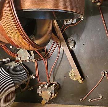
Close-up showing the Bell Crank levers for adjusting the Inductor Coupling and the Tickler Coil Coupling. Also, the knife-switches for "Tuned-Untuned" and "Detector Switch" functions.

NESCO History - National Electrical Supply Company, a supplier of many types of electrical and automotive electrical parts, was located in Washington D.C. NESCO worked closely with the U.S. Navy during WWI producing various types of electrical equipment and specializing in wireless receivers. Several types of receiver-tuners were built for the Navy with the SE-143 probably being the type that was produced in the greatest quantity. Continuing to work with the Navy after WWI, NESCO produced several types of "add-on" equipment to upgrade some of the WWI receiver-tuners. NESCO was added to the SE-1420 contractors in 1924 after AMRAD went bankrupt. National Electrical Supply Company is sometimes confused with Reginald Fessenden's company, "National Electrical Signaling Company" since both are usually referred to by the acronym, "NESCO," and there are and have been many National Electrical Supply Companies but NESCO, located in Washington D.C., is the historic company, founded in 1899, that is associated with the Navy Department during WWI and after. In 1937, NESCO incorporated and changed its name to National Electric Machine Shops using the acronym NEMS. NEMS and Alan Clarke merged in 1955 as Nems-Clarke, specializing in high-end commercial-military VHF radio equipment and building NEMS-Clarke VHF receivers for missile telemetry reception. NEMS-Clarke was purchased in 1957 by Vitro Electronics but NEMS-Clarke continued building VHF equipment and using the "NEMS-Clarke" name with Vitro Electronics only shown on the data plate. As for Fessenden's NESCO, it was reformed into International Signaling Company in 1917 and then, after WWI, was purchased by Westinghouse to form their International Radio Telegraph Co.
 

Refurbishment, Testing and Operation

Refurbishing the SE-143 - This receiver had been stored poorly, probably for decades. The back of the cabinet had been missing at some time in the past and that allowed some type of pest to take up residence in the Secondary Coil. Luckily, it wasn't a mouse family since none of the wiring was eaten or even nibbled on. Lots of dried-up debris like leaves and what looked like dog hair. It all cleaned up easily using Glass Plus and Isopropyl Alcohol. Cleaning the Primary and Secondary condensers took a lot of time using various brushes and lots of Glass Plus. After several "flushes" using Glass Plus, the rotor plates and the stator plates were further cleaned by sliding a folded piece of heavy paper through the spaces to remove any other debris. Although this process was rather time-consuming, it resulted in the air-variable condensers looking excellent and working as they should. The inductor windings looked in good condition but the two bell crank lever controls were very stiff and hard to move. The same "stiffness" was found in all of the controls. Careful cleaning followed by lubrication using very small amounts of WD-40 loosened up all of the controls. I also used DeOxit on the knife-switches and on the contact switches. Since there aren't any active components in the SE-143, all that's required is that the inductors and variable condensers are in good condition and that the contact switches are also working correctly. Essentially, the circuitry is almost all mechanical and this requires that all contacts are clean and all wiring is present. What is astounding is that this 100+ year old radio apparatus is complete and all original. It has never even had any soldering work performed on it and, other than the indications of less-than-perfect storage, the chassis is pretty much as it was built by NESCO back in 1918,..amazing.


S.E.143 data plate - The 3000M lower end of tuning is specified because extending the Primary tuning range to 6400M required an external parallel LC connection.

Cabinet Work - The SE-143 cabinet is made out of walnut stained a dark reddish-brown color. The interior has no metal shielding installed. The right side front of the cabinet has two broken pieces of wood that are the full length of the height of the side piece. I had to remove the two latch-bails to be able to glue these pieces back correctly. The bottom front section is split and broken requiring gluing and clamping. I use Franklin's Genuine Hide Glue for this type of repair (Franklin's has now been replaced by Tite-Bond Hide Glue.) This Hide Glue is not the old type (rendered from horse hoofs and hides) that needed to be a hot smelly liquid that was quickly painted on and set-up as soon as it cooled. Franklin's is synthetic hide glue with all of the good properties and minus the disadvantages. This glue is amber colored and transparent (Tite-Bond is semi-transparent) so it looks old if it happens to show in the joint. It does take a fairly long time to set-up but the glued joint has to be clamped and let set for about an hour. For full strength the glue joint must dry overnight. Unfortunately, with these types of breaks, I have to use a combination of hand clamps and pipe clamps because of the distance between the glue joint and the back of the cabinet and because of the angle of the breaks. The need for pipe clamps is common with most cabinet repairs involving glued joints. The complete gluing took about a day to accomplish and used three pipe clamps and about half a dozen hand clamps.

I do have the rare front cover for this SE-143. It has had some crude repairs done to it. The cover piece of wood was replaced with 1/2" plywood, apparently many years ago. It's stained to a color that's sort of close and has a vintage-look to it. Also, one of the side pieces was replaced and the dove-tail joints not reproduced. Instead, the "dove-tails" were cut off and the wood nailed in place. It's pretty crude. Overall, the condition is probably a little worse than average BUT,...on the average, the front cover is usually missing. At least, I do have the top cover, which is rare to find with an SE-143 receiver. 

The Rear of the Cabinet Dilemma - The back of the cabinet ended up missing sometime in the past. A former owner cut some 1/4" birch plywood, glued two pieces in a sandwich to create a 1/2" thick, stepped-type of back that fits okay. It wasn't stained and finished however, just left bare wood. Luckily, it's mounted with only four screws, so it can be easily removed for rework and staining. I have lots of red mahogany stain but I think I'll have to mix some golden oak in to get the correct color. I'll also work on getting a better fit, touching up the edges so they don't look like plywood and then stain to match. For the time period and that fact that most of the SE-143 receivers were expected to be "at sea" I'd expect spar varnish was the original finish used. However, after 100 years, there's not too much original finish left now. Close examination of the SE-143 cabinet with this make-shift cover removed and there doesn't seem to be any evidence of how a back cover was attached. I can't find any residue of glue and there aren't any nail or screw holes. From examination of other similar vintage types of cabinets (but, unfortunately not SE-143 cabinets,) the typical back cover would fit into the rear opening of the cabinet. There wouldn't be any finger joints or anything visible from the exterior to indicate how the rear cover was secured. My guess is that these types of rear covers were glued using hide glue. Why there isn't any evidence of glue in my SE-143 cabinet is a mystery although hide glue does dissolve in water or high humidity. To make a replacement rear cover would require using solid walnut about 1/2" thick. Typically, these back covers were made from 3" wide strips glued together to the dimensions necessary for the height of the cabinet. This requires a professional wood-working ability and the proper tools. Then after the strips are glued together, the rear cover has to be cut precisely to fit into the rear opening. Lots of professional-level work. For now, since the make-shift cover fits okay and after staining it matches fairly well, I'm going to use it. A side-benefit of this back cover is that it significantly strengthens the cabinet joints but I think that would also be true of an original type of back cover.

Testing the SE-143 - Preliminary Test - Since the SE-143 is an RF Tuner, a different type of testing must be performed to determine if it was going to be operational. I used the HP-606B RF Signal Generator and the FNIRSI DPOS350P "tablet-type" oscilloscope. I connected the 'scope to the RA and RE terminals (the Secondary LC - tuner output) and connected the signal generator to the ANT and GND terminals. I first set the sig-gen to 600 meters or 500kc with no modulation. The oscilloscope showed a sine wave at the RA/RE terminals. A little bit of adjusting and the signal was easily peaked for maximum sine wave showing on the 'scope. I tried various frequency inputs ranging from 800kc down to 60kc and I was able to peak the signal on all ranges. This indicated that the RF Tuner did function as far as being able to adjust resonance in both the Primary and Secondary tuners. I performed the same tests using a 400hz modulated signal, not that I expected different results but just out of curiosity to see what a modulated waveform looked like.

Crystal Detector Test - The next test was to connect a crystal diode (1N34 germanium diode) to the CRYSTAL terminals (it doesn't matter for the cathode or anode connections.) I connected a set of Baldwin Type-C 'phones to the TELEPHONE terminals. I placed the DETECTOR SWITCH in the CRYSTAL position. I had the SE-143 tuned to 1000 meters or 300kc and the HP-606 was also tuned to 300kc modulated at 400hz. The signal came over the 'phones quite well. It did require a little bit of peaking of both the Primary and Secondary tuners for a maximum response. I tried a few other frequencies and was able to tune them in quite well.

Signals "Over the Air" Test - Next was to try an actual "over the air" signal. About the strongest MW signal around here is from KKOH on 780kc or about 385 meters. I used the HP-606 to pre-tune the SE-143 for 780kc. I connected one leg of the Collinear Array for the antenna (about 250 ft end-fed wire) and used the house ground. KKOH 780kc was easily audible and, with a little peaking, it was coming in strong using the 1N34 crystal detector. I tuned in a couple more BC stations, KPLY on 630kc and KOLO on 920kc. With the COUPLING on 110, I had enough selectivity to separate these stations easily and still maintain a good signal level. I tuned to "S" which is the WWI letter designation for 100kc (3000 meters.) This is the transmitting frequency of the LORAN-E Master Station "M" located in Fallon, Nevada about 50 miles east of my QTH. "M" runs 400KW to a 625' tall ground isolated vertical with a 900' C-hat,...it's a formidable LF signal here in Dayton Valley. "M" was easily tuned in and peaked with the Secondary Condenser exactly on "S." If the TICKLER coil is shorted for CRYSTAL detector operation (as when using the SE-1071) then the TICKLER COUPLER should be set to MIN to minimize coupling losses in the Secondary Inductance.


"IN and OUT" test, showing the output at RA/RE (Secondary LC) - 500kc sine wave input on ANT input from HP-606B with no modulation. The FNIRSI DPOS350P shows 500.3khz on the DFC and shows the output is 1.82VP/P. This preliminary, no detector, test showed that a signal could make it from the Antenna to the "Tuned Output."

VT detector and Regeneration Test - The SE-143 was normally used as an RF Tuner ahead of a Vacuum Tube detector. Using a Crystal Detector was generally only for emergencies where no power was available to operate the tube or tubes. The SE-1071 was the Audion Control Box and it interconnected with the eight vertically aligned terminals on the right side of the receiver.

The Hook-up - To operate the SE-143 with a VT requires a vintage triode tube and tube socket, an adjustable filament voltage source and another adjustable voltage source to provide plate voltage. A couple of things to observe are RE is connected directly to F- and B- is connected to F+. The 'phones are connected to the AUD TEL terminals. The plate voltage B+ is also connected the lower AUD TEL terminals that has one lead of the 'phones. The top AUD TEL terminal has the other lead of the 'phones but also has a jumper to connect the upper AUD TEL terminal to the lower TICKLER terminal (the use of the AUD TEL terminals was later found to be unnecessary.) Then the upper TICKLER terminal is connected to the Plate terminal on the tube socket. The jumper has to be externally installed because this connection was actually made inside the SE-1071. Additionally, the connections to 'phones, Tickler Coil and VT plate were all internal to the SE-1071 and controlled by a switch that selected OSCILLATOR (Regen going through the Tickler coil) or DETECTOR (Tickler coil shorted for a non-regenerative detector.)

The Ship's Generator as a B+ Source - Interestingly, the SE-1071 could provide B+ plate voltage either from storage batteries or it could be provided by the ship's +125vdc generator. There was an adjustable potentiometer to adjust the plate voltage but the +125vdc ship's generator only has a couple of filter chokes inline inside the SE-1071, so one has to wonder exactly what the plate voltage was and what the value of the variable resistance was (neither are indicated anywhere on the SE-1071 schematic. Sterling's Radio Manual indicates the resistance was 30,000 ohms. Plate voltage could be adjusted between +60vdc and +90vdc if the ship's generator was used.) There's a switch and terminals provided for selecting either storage batteries or the ship's generator as a B+ voltage source. If the SE-1000 Audio Amplifier was also to be used, then the ship's generator couldn't be used and only storage (or dry) plate batteries could be used. When using B batteries, the adjustable plate voltage function is disconnected.

Vacuum Tubes Available in 1918 - Another consideration is the actual type of vacuum tube used in the SE-1071. In 1918, a Moorhead "ER" Electron Relay tube might have been used or perhaps a Western Electric VT-1. Other tubes specified in Sterling's Radio Manual are the Western Electric W-933 or the General Electric CG-890. Both of these tubes have 1 amp filament requirements indicating a pure tungsten filament and a plate voltage specified from +20 up to +60vdc. The specs of those two types of VTs are similar to the UV-200 or UV-201 but those tubes weren't introduced until around late-1921, along with most of the other consumer-broadcast radio vacuum tubes (although the UV-200 or UV-201 tubes weren't available in 1918, they can, of course, be used today.) Apparently, in late-1920 and through most of 1921, Westinghouse supplied WR-21 tubes that were similar in specifications to the UV-201 (4vdc@.8A compared to 5vdc@1A) however the socket required for the WR-21 was different. The tube sockets used in the SE-1071 and the SE-1000 audio amplifier were for Shaw base tubes, that would be the standard twist-lock, bayonet shell, four pin socket. The WE-215A tube might have been available in 1919, but the special socket required for that tube seems to eliminate it for use in the SE-1071. The most likely VT used in 1918 would have been the WE VT-1 or the Electron Relay (there were several manufacturers for the ER type of VT during WWI) or those specified in Sterling's Radio Manual. For initial testing of VT detector and regeneration, I'm going to use the UV-200.

What Doesn't Work - My first attempt with the UV-200 had clip-leads improvised with very long lead connections and didn't follow what the SE-1071 schematic indicated. As expected, while this lash-up worked fine as a non-regenerative Detector, I couldn't get the Detector to break into oscillation. I tried using a UX-201A and a Type-30 with the same results. I tried plate voltages from a low +15vdc up to +70vdc and could never get any of the Detector tubes to oscillate.

What Does Work - Finally, I decided to follow the SE-1071 schematic and hook-up closely, in fact, almost exactly. I used wire connections that were as short and direct as possible. I connected one lead of the 'phones to the lower TICKLER terminal and the other 'phones lead to +45vdc. The upper TICKLER terminal was connected to the detector tube plate. Connecting to the AUD TEL terminals isn't necessary. I think the non-oscillating problem was that initially I had connected the RE terminal to F+/B- but, the SE-1071 schematic shows RE connected directly to F- battery terminal. I made the change so that the F- connection agreed with the SE-1071 schematic. I replaced the 250pf grid blocking cap with a 500pf. The grid blocking cap is a switch-selected value in the SE-1071 and 500pf is in the middle of the range of capacitors. I changed the grid-leak resistor from 1.2meg ohm to 680K (600K on the SE-1071 schematic.) I connected the grid-leak to B- as indicated on the SE-1071 schematic rather than in parallel with the grid blocking cap. I installed a 0.004uf capacitor from the junction of the 'phones and the Tickler coil as indicated on the SE-1071 schematic. It's a switch-selected value but the capacitor values aren't shown on the SE-1071 schematic. The capacitor shunts any RF on the 'phones to B-.  NOTE: Experimentation has shown that this capacitor is essential for allowing the detector to oscillate. Also, something to consider if AF amplifier stages are added and this capacitor is moved to the primary of the first interstage transformer. If the capacitor is connected to B-, then, if the capacitor shorted, the increased current flow through the transformer primary could cause it to "go open circuit." Most circuits will have this capacitor connected to Detector B+ (across the primary using Det B+ as a low impedance source) where it still functions as needed and if the capacitor shorted it wouldn't damage the interstage transformer.

Following the SE-1071 schematic and the hook-up exactly as shown resulted in tremendous regeneration capabilities with being able to easily adjust the TICKLER COUPLER for detector oscillations.

In actually operating the SE-143 and testing various wavelengths of reception, I've discovered that it helps to have the filament voltage adjustable. The B+ can be a fixed value. I used +45vdc on the detector plate because I had switched the tube type to a 201-A operating as a "hard detector." I found best improvement was when I eliminated as many of the clip-leads as possible and installed wires that were soldered to lugs that were then installed to the tube socket terminals. Where the wire went through the hole in the SE-143 terminals I tinned wire end to make as good of a joint as can be expected from thumb-nut terminals. Also, making sure that the RE terminal connected directly to F- and that the filament adjustment pot was connected from F- on one end and to F- at the tube socket on the other end. With careful wire connections that followed the SE-1071 schematic, I was able to tune down to 5000M (60kc) and could easily maintain an oscillating condition for the regeneration. 

Long Wavelength Loading Coils - Necessary below 50kc -  If it was necessary to receive stations transmitting on wavelengths longer than 6000M (50kc) and the SE-143 was the only receiver available, then additional inductance in the Primary, Secondary and Tickler coils had to be connected to the appropriate front panel terminals. With the additional inductance, the Primary tuning can become ineffective at longer and longer wavelengths (although the antenna used is an important factor at these lower frequencies.) Two of the vintage photos (below) of SE-143 stations show that LF Loading coils were in place. The NAA Station used massive inductances with tapped switches. The USN Shipboard station used a Remler Type Duo-lateral Tuner with LF honeycomb plug-in coils. Sterling's Radio Manual gives the number of turns for the specific plug-in honeycomb coils used in a Duo-lateral Tuner (and typical plug-in honeycomb coils usually have a label on the inside opening indicating the number of turns in the coil.) On average, 700 to 1000 turn coils can be used for the Primary and Secondary Inductances and a 600 to 750 turn coil used for the Tickler. When setting up for using Loading Coils, Position 6 should allow the SE-143 to tune slightly below 50kc (approximately 47kc) without the Loading Coils connected. I believe that if LW loading coils were used, the operator would place the Secondary Inductance switch to position 6 and then connect the LW coils. The LW coil setup should have a method to "short" each of the coils to remove them from the circuit (like the shorting straps do for the Primary and Secondary L and, since the Long Wavelength Tickler coil is connected in series, shorting just the coil is also proper to remove it from the circuit.) When the LW coils are placed into the circuit, that would then allow tuning to wavelengths longer than 6000M (50kc) with the Secondary Inductance in position 6. Of course, adding the LW Loading Coils will affect the total inductance and thus all tuning ranges would be effected. However, with LW Loading coils installed, the receiver's standard Primary and Secondary total L is very low when compared to the large inductance of the loading coils, so the action of changing the L switches on the SE-143 doesn't have too much of an effect on tuning (the tuning is all in the variable condensers.) With a setup for LW coverage at wavelengths longer than 6000M, then the selection of position 6 allows the user to add markers (pencil notations) to the Secondary Condenser tuning dial in the blank area just above the position 6 scale These pencil notations could be used to set the Secondary Condenser dial for the desired wavelength for future resetting of the tuning. Sterling's Radio Manual also shows a method to connect the Primary Condenser in parallel to the Primary Inductance for better LW tuning (it's easily accomplished by just using the PRI LOAD COIL terminal for the antenna input and shorting the ANT to GND terminals) Sterling also indicates that the TICKLER coil might have to be reverse-connected when using LW Loading Coils and operating on long wavelengths although he's not specific if the reversal is for the Tickler Loading Coil connections or for the SE-143 Tickler terminals (experimentation would be required.) From examining vintage photos it seems obvious that LW Loading Coils were common in the typical SE-143 installations and there certainly were a lot of stations operating in the part of the spectrum during the post-WWI time period. All USN Alexanderson Alternator Transmitters were operating below 50kc. Many other VLF stations were used for "Navy Radio Central" type communications to various fleets. Time signals, some navigation uses, etc., were also found in the VLF (the frequencies below 30kc) part of the spectrum. Loading Coils were definitely going to be necessary if the SE-143 was the only receiver available in the ship's radio room.
Adding a Single Stage of Audio Amplification - I have a Pilot Radio Redi-Blox Single Stage Audio Amplifier from about 1930 that I use with the SE-1420 receiver to boost the output of the detector tube for that receiver. It provides enough audio level to actually hear very weak signals, like NDBs, using headphones. I've also used this audio amplifier with the Spherical Audion Receiver with good results.

To hook-up the single-stage AF amp, the primary winding of the input transformer is connected to the two points where the headphones were connected,...to the lower TICKLER terminal directly with one end of the primary and the other TICKLER terminal connecting to the detector plate. The other transformer primary terminal is connected to detector B+ with the voltage being +45vdc for a UX-201A tube. For the Audio Amplifier tube I use a UX-201A tube and use +90vdc on the plate and that is routed through the 'phones before going directly to the amp's plate terminal. The F+ and the B- are connected to the B- terminal of the A-B power supply (B- is connected to F+.) Audio Output can be controlled by the tube filament voltage. A 1920s Horn Speaker could be used on just about any of the AM-BC stations. Hearing NDBs (the few left, anyway) will require 'phones and listening during LW Season (between the Autumnal Equinox and the Vernal Equinox - definitely not in mid-July.) The NDBs are MCW signals but having the detector oscillating will make finding the NDB's carrier easy. Just tune for zero-beat and the MCW tone will be easy to copy. 

The photo to the right shows the SE-143 after cleaning and installation into the repaired cabinet. The white and black leads near the Buzzer are the Antenna and Ground connections. The antenna is one half of a Collinear Array or about 250 feet of wire that's end-fed and the ground is a combination of the house ground and a large counterpoise. The power supply is a homebrew, active regulated type with full switched metering. I designed and built this A-B-C eliminator in the late-1970s when I had practically unlimited new parts available at no cost. Filament supplies are +1.5vdc, +4.5vdc and +6vdc and use 3A active regulators. B supplies +22.5vdc, +45vdc, +67.5vdc and +90vdc are actually four completely individual +22.5vdc power supplies with their own power transformers with 1A active regulators. The B supplies are connected in series for the B voltages. The C bias supply is -4.5vdc uses a small active regulator for 200mA. I also built-in switched metering for A and B supplies. The A meter switch also selects which filament voltage appears on the A terminals. I should have made the A supplies adjustable but since they aren't, I've connected an external filament rheostat (0 to 10 ohms adjustable.) I've eliminated as many of the clip-leads as possible. Most wires are soldered to lugs that are then installed to the terminals. This careful setup has resulted in a greatly improved performance.


SE-143 with VT Regenerative Detector and Single Audio Amplifier is tuned to 5000M or 60kc receiving WWVB PE Time Signal. As to the "haphazard" interconnect wiring,...the SE-143 manual does state that the wires shouldn't be "bunched" - they aren't.

Over-the-Air Reception Testing - As can be seen in the photo above-right, I have the SE-143 tuned to 5000M or 60kc and I'm receiving WWVB quite well. The detector is oscillating so sensitivity is excellent. The strongest signals in LF around here are the Loran-E Master Station "M" located in Fallon, Nevada running 400KW on 100kc, then there's an unknown MSK station (possibly USN) around 75kc that's pretty strong and then WWVB on 60kc. Going lower in frequency, that would be lower than 50kc, would require a LW Loading Coil setup (I've constructed a replica of a Remler Duo-Lateral Tuner for use with plug-in LW coils.) The next strong stations are the Navy Sub-Comm MSK VLF stations transmitting around 24kc. There are five large USN VLF Stations that transmit at incredible power levels to immense antenna arrays so their signals are formidable and easily received. Also, JJY is Japan's LF Time station on 40kc. JJY isn't a terribly powerful signal here near the West Coast of the USA but just before sunrise it's easy to receive (JJY 40kc runs 10KW.) On 12kc, 14kc and 15.6kc, the Russian RSDN-20 Alpha Nav transmitters operate. These are also easy to receive since they run 500KW to large array antenna systems. There are three major Russian Alpha transmitting sites and three other support sites. All are in central Russia. The 12kc RSDN-20 signal is the lowest frequency identifiable signal that's fairly easy to receive.

Since the SE-143 has absolutely no shielding, when the regenerative detector is oscillating there will be some "hand-capacitance effect" on the TICKLER COUPLER control, on the SECONDARY INDUCTANCE SWITCH and to a lesser extent on the SECONDARY CONDENSER and the INDUCTANCE COUPLER controls. Since these components are part of the oscillating detector there's an associated EM field around the components and when the hand is on the control knob there will be a slight de-tuning because the hand adds "capacitance to ground." This is a common effect with unshielded regenerative receivers. The hand-capacity effect lessens as the wavelength lengthens, that is, the lower the frequency the less hand-capacity effect will be experienced. The SE-1420 solved this problem by entirely shielding the front panel and the cabinet along with a divider shield between the Antenna Tuner and the Secondary LC.

Summer conditions are terrible for MW and LF reception,...but I thought I'd try to at least receive the NBD MOG 405kc located in Montegue, California. It's the closest NDB to Dayton Valley, Nevada that's still in operation with a distance of about 150 miles. I pre-tuned the SE-143 using a signal generator for the marker signal. With a slight amount of "peaking" I was able to hear MOG very well. Time of reception was 2135hrs PDT on Jul 14, 2026. I tuned around by didn't hear any other NDBs (and that's not particularly surprising for mid-July listening.)

Since a clip-lead connected regenerative detector and single stage audio amplifier using components that are just setting on the table tends to be unstable, I thought I'd go ahead and build something a little better,...

Building a Regenerative Detector, 2-Stage Audio Amplifier for the SE-143

Components and Construction - If you have the parts required, this hookup is pretty easy. I had saved an old faux mahogany bakelite panel that was attached to a 3/4" thick piece of redwood acting as a breadboard chassis. Many years ago a one-tube radio project was started using this relic but, since it was never finished, those parts had been stripped-off long ago. All that was left was this bare breadboard and panel. I had saved it because I knew I would be able to use it for some type of project some day. It was a good size for a Regenerative Detector and 2-stage Audio Amplifier (hereafter referred to as the D-A) using three breadboard-type tube sockets, two matching interstage transformers and two wire-wound rheostats. I also had nine very large bakelite-capped binding posts and a vintage telephone jack. Breadboarding is an easy construction method since the components basically are screw-mounted to the wooden base. I did have to drill a few holes in the bakelite panel but it was all easy work. Once the components were mounted, then the wiring could be installed. It's all pretty straight-forward when using "sort of modern" insulated, solid conductor wire. I didn't use the buss wiring technique because it was obvious this wasn't going to be a replica. It was just going to be something useful for testing various types of vintage RF tuners. I used 201-A tubes since they are plentiful and function fine for this particular application. Gain is x10 for each AF tube and with 3:1 transformers, total audio gain is 900. If the amplifier plate voltage used is about +60vdc then a -C bias probably isn't necessary. For better audio (well, higher output level,) the amplifier plates should run at +90vdc and the grids should be biased with -4.5vdc. I've wired the D-A to easily attach a -4.5vdc battery for the bias voltage using two Fahnstock clips mounted at the rear of the wooden chassis. The bias battery is made from three AA batteries connected in series. If -C bias isn't needed, then the two Fahnstock clips can be shunted and that connects the grids directly through the interstage secondary windings to A+/B-.


Schematic for Regenerative Detector and 2-Stage Audio Amplifier

Using Just the 2-Stage Amplifier for the SE-1420 - It's very easy to bypass the D-A detector stage and access the first interstage transformer primary to provide a 2-stage AF Amp for a single-tube regenerative detector receiver, like the SE-1420. The D-A interstage primary substitutes for the TELEPHONES input but the SE-1420 supplies the Det plate voltage. Just connect the lower TICKLER binding post on the D-A to one of the SE-1420 TELEPHONES terminals and the D-A DET B+ binding post to the other SE-1420 TELEPHONES terminal. Turn the D-A Det Fil rheostat to OFF. DO NOT connect the D-A DET B+ to an external voltage, the SE-1420 will supply the detector plate voltage. D-A filament voltage is required for the Audio tubes only and is controlled by the Amp Fil Rheostat, the +90vdc Audio tubes plate voltage and the -4.5vdc C bias voltages will still be required as will the filament and detector voltages for the SE-1420.

Using the Homebrew Regen Det-AF Amp with the SE-143 - I used the homebrew A-B-C supply with +45 Det B+ and +90vdc Amp B+. The -C bias was -4.5vdc and the A supply was +6.0vdc. The capacitor across the first interstage primary is essential in order to shunt the RF to a low Z (low-impedance in this case is B+ and don't connect the capacitor to A+B- because if it shorts-out the excessive current flow could cause the primary winding of the transformer to go open-circuit.) Without this capacitor installed the SE-143 won't regenerate. Also, +45vdc is necessary on the Detector plate for regeneration below 100kc (when using a 201-A tube, +22.5vdc isn't enough plate potential for regenerative oscillation at the lowest RF frequencies.) All of the controls that are adjustable will have an effect on reception, so expect a lot of interaction. The easiest method is to set the COUPLING to the some moderate selectivity, around 60 is okay to start. Then tune the Secondary LC to the approximate wavelength and adjust the TICKLER for oscillation. Then peak the Primary LC. It requires going back and forth a lot to get all of the adjustments correct for maximum signal response,...and that's normal for a regenerative detector tuner. Setting "Critical Coupling" is very important with a three-circuit tuner using an oscillating regenerative detector. To set "Critical Coupling" requires the following steps,...after the station is tuned in, then use the Primary Condenser to "tune through" the signal. If you hear the regeneration "click" or "shut off," then the Coupling is too tight and needs to be loosened, that is, reduced. Turn the Coupling control to a lower number on the scale, e.g., if you were at 60, lower it to 40, then tune through the signal with the Primary Condenser again. If the signal still "clicks" or "shuts-off," reduce the Coupling to an even lower number. Repeat these steps until as you tune through the signal with the Primary Condenser it just peaks with no "clicks" and no "shutting off." Now the Secondary Condenser can be used to peak the signal and the Tickler adjusted for maximum sensitivity. Setting "Critical Coupling" is very important when searching for weak CW or MCW signals and requires that both the Primary and Secondary condensers are tuned together for maintaining peak signal response. I was able to easily achieve feedback down to 50kc (with +45vdc Detector plate voltage.) I did most of the listening on LF with WWVB 60kc, the USN MSK station on 72kc, Loran-C 100kc used for testing. AM-BC was also used for testing. All signals were monitored on a Western Electric 10-D horn speaker. Aug 19, 2026 - Using LW Loading coils and the D-A, I was able to receive NWC 19.8kc USN MSK Sub-Comm Station in Exmouth, Australia. Also, NPM 21.4kc in Lualualai, Hawaii and NAA 24.0kc in Cutler, Maine and NLK 24.8kc in Jim Creek, Washington,...all listening over the WE 10-D Horn.


Det-2AF Amps with used parts and Breadboard construction. The tubes are 201-A types. The matching 3:1 interstage transformers aren't marked so the maker is unknown. Most of the wire used was vintage solid 18ga conductor that allowed for nice bending for the routing of the wires. The blue tape markers identified the proper connections for the interstage transformers.


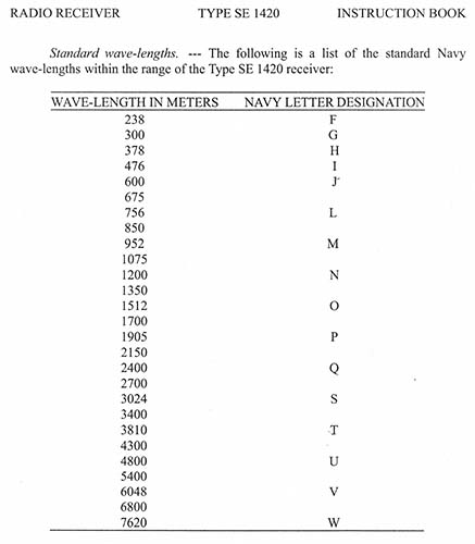
Letter Assignments for Wavelengths as Shown on SE-143 and SE-1420 Secondary Condenser DialsI always wondered what the letters on the Secondary Tuning dial indicated. Of course, it was obvious that the letters indicated important and specific wavelengths that allowed the receiver operator to easily find a particular known transmitted signal. The interesting thing is that no wireless book mentions these letter designations used by the Navy. Also, even the SE-1420 Instruction Book, that has a listing of the letter designations, doesn't mention what they were specifically used for. The listing is shown to the right. Speculation would be that neophyte radio operators were confused by all the various numbers involved with wavelengths and then the Secondary Tuning dial required the radio op to multiply by 100 to actually determine what wavelength the dial was tuned to. It was easier to just indicate the important wavelengths by a letter designation and then setting the Secondary Tuning dial was essentially a "one step" process with no math involved. Possibly setup charts or instructions were used although this is never mentioned in books like Sterling's Radio Manual. Probably just the "wavelength to letter designation" was sufficient. At any rate, the Navy receivers, the SE-143 and the SE-1420, both have these letter designations on their Secondary Tuning dials but the IP-501-A, a commercial receiver, doesn't have the letter designations. Note that the list shown to the right does indicate that these are "standard Navy wave-lengths" and that the letters are the "NAVY LETTER DESIGNATION."

Renewed Usability for the SE-143 for the 1920s - The SE-143 "aged" quickly and, by 1920, other more advanced designs were being developed and introduced into the Navy. Possibly, the need for specific types of detector tubes became a problem as vacuum tubes evolved (although Sterling's Radio Manual gives the specs for using UX-201A tubes implying the continued use of the SE-1071 into the 1920s.) The SE-143 was still an excellent RF Tuner that could still provide very selective tuning so newly designed "add-on" units were introduced around 1922. These add-ons enhanced the performance capabilities of the SE-143 allowing the Navy to continue using it, in combination with some of the external devices, to modernize the performance and that allowed the SE-143 to continue on as a shipboard tuner-receiver for several more years. Two of these types of "add-ons" are profiled in the next section following (after the "NOTES.")

 
NOTE 1: Where did this SE-143 come from? I received a 'phone call from Ethan, the owner of Ham & Hi-Fi in Sparks, Nevada, saying "I have something here that's right up your alley!" He was right, of course. I had to think about it for a couple of weeks due to the condition problems. Ethan had texted me a few photos of the receiver that showed some of the issues (that looked worse than they actually were.) When I decided to go ahead with the purchase, then Ethan was out of town for about three weeks. Finally, after our mutual delays were over, I was able to purchase the SE-143 on June 30, 2026. Ethan told me that the SE-143 had been stored in Santa Rosa, California.

NOTE 2: The U.S. Navy created the Bureau of Steam Engineering in the 1860s as a technical engineering department, initially to help with the transition from sailing ships to steam powered ships. Later, new technologies like electrical and wireless engineering were added. In 1920, the name was changed to Bureau of Engineering and, in 1940, it was renamed Bureau of Ships.

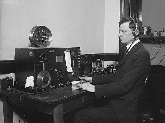
NOTE 3: Although I've seen some written references to an "A" version of the SE-143 (supposedly designating the NESCO builds,) I really haven't found any early (contemporary to the SE-143 production and use) that specified that an "A" version existed or, if it did, what an "A" version consisted of. That being said, there are many variations of the SE-143. There's a photo of one on the Internet that has a reddish-brown panel, cabinets can be found in walnut or oak, there are variations in the types of buzzer buttons, at some point the CRYSTAL-AUDION switch nomenclature was changed to AUDION-SEND-CRYSTAL with the AUDION and CRYSTAL positions exchanged and a SEND position added (probably the mid-position where the knife-switch arms don't contact either of the stationary receptacles.) Some variations were probably due to specific builders, e.g., the differences between a Wireless Specialty Apparatus build and a NESCO build. It's also possible the differences were between the SE-143 (typically NESCO) and the IP-500 (typically Wireless Specialty Apparatus.) See the vintage photos further down, in particular the photo of Paul Sollenberger. The receiver shown has many similarities to the SE-143 but was obviously designed for later peripheral equipment. Maybe it's an SE-143A.

NOTE 4: The "Short Wave" designation is relative to the time period and to the typical frequencies that the Navy used during WWI. A more modern designation would be that the SE-143 is an LF/MW RF Tuner-Receiver (Low Frequency or LF is from 30kc to 300kc and Medium Wave or MW is from 300kc to 3000kc.


SE-1387 - R.F. Driver (Tuned Heterodyne Oscillator)  SN: 15N
  SE-1834 - Amplifier, Radio-Audio 125-30,000 Meters, Audio Universal
(3-stage Broadband RF amplifier, Detector, 2-stage AF amplifier)  SN: 14N

Navy Department - Bureau of Engineering - National Electrical Supply Company (NESCO) - 1922 Contract
 

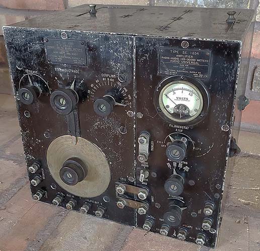
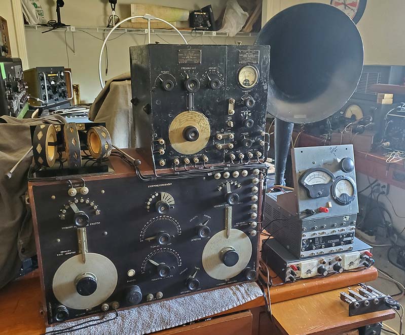
Post-WWI Radio Improvements - As radio evolved post-WWI, the need for new radio equipment was offset by the reduced post-war Navy budget that limited extravagant purchases to a certain extent. This resulted in the newest and largest Navy ships being prioritized for the newest equipment while an older or smaller ship would have to utilize older, maybe even WWI-era, radio gear. Improvements were much easier to fit into the budget and, as radio evolved, these external circuit additions allowed older radio equipment to be updated to provide usable service. Most peripheral equipment came in the form of RF amplifiers to be used ahead of a regenerative detector provided stronger signals and antenna isolation. Audio amplifiers to provide stronger post-detection signals to drive multiple outputs. Devices for interfacing specialized antennas such as loop antennas for direction finding. By 1922, there were several types of "add-on" devices available to improve the performance and usability of older receivers. This SE-1387/SE-1834 combination (shown to the right) was specifically for the SE-143, IP-500, SE-1220 or other similar RF Tuners.

Although the SE-1387/SE-1834 combination appears to be a receiver, it's far from being a "complete" receiver. The SE-1387 is actually a "tuned" Heterodyne Oscillator and the SE-1834 is almost a complete receiver but it's minus any selective RF tuning capability. Both units have to be used with RF Tuner sets like the SE-143. Unlike the earlier shipboard radio equipment that were housed in wooden cases, perhaps lined with metal shielding, the SE-1387/SE-1834 combo was built with aluminum front panels and housed in an aluminum case. Both units are installed into individually shielded compartments to prevent any stray coupling between the units. The size of the metal cabinet matches the height of the SE-1420 so it's somewhat smaller than the enormous cabinet of the SE-143. Most Navy installations would place the "add-on" units on top of the SE-143 and wires interconnecting the units were routed around the panels to access the needed terminals. Although this particular example has the SE-1387 and the SE-1834 housed into a single cabinet, most vintage photographs show individual "add-on" units were single-function devices that were housed in their own individual cabinets (see the vintage photos further below.)


SE-1387 & SE-1834
Combination RF Driver and RF-AF Amplifier & Detector


RF Driver (Heterodyne Oscillator) SE-1387 - The Oscillator tuning condenser is controlled with a two-speed tuning dial assembly.

The SE-1387 Details - This device was called an R.F. Driver, though nowadays that's an unfamiliar term that doesn't describe the circuit's true function. During the WWI era, Wireless Specialty Apparatus Company produced a device called an "Eaton Oscillator" that when connected to a tunable LC would provide a constant oscillation for detecting undamped waves (a Continuous Wave signal.) By adding a few parts, the Eaton Oscillator became the "Eaton Circuit Driver" that performed as an Eaton Oscillator but also could produce an output from a damped wave via a buzzer that could "drive" a wavemeter for calibration. At the time the SE-1387 was designed, the "RF Driver" term was probably used because, while it didn't directly use the secondary LC, it was used to "modulate" a continuous wave signal to produce an audible heterodyne, something like the Eaton Circuit Driver but acting as a much more versatile "heterodyne oscillator." Hereafter, I'll refer to the SE-1387 as a "Heterodyne Oscillator." The SE-1387 tunes from 125M up to 30,000M (2400kc down to 10kc.) It uses a single WECO 215A tube that's designed to function as a tunable RF oscillator and, when connected in series with the SE-143's RE connection to the VT detector, it provided an electro-statically and variably-coupled RF oscillator that when tuned to the RF Tuner's operating frequency would provide heterodyne action (a beat note) for CW reception from Arc transmitters, Alexanderson Alternators and Vacuum Tube transmitters. This type of on-frequency heterodyne action allowed reception of the CW mode without requiring a self-oscillating detector (a regenerative Autodyne detector.) The advantage of using the SE-1387 was it's consistent ability to provide a heterodyne tone regardless of the received frequency. Using a regenerative detector set up for self-oscillation works quite well but its adjustment needs are constant and in some cases, due to antenna loading or plate and filament voltages used, a regenerative detector won't oscillate. With the heterodyne oscillator, a beat note could be set-up at any frequency the receiver was tuned to. These types of heterodyne oscillators had to be tuned to the received frequency since there was no down-conversion of the tuned frequency as would be found in later superheterodyne receivers where the BFO operated at the Intermediate Frequency of the receiver and was capacitively-coupled into the detector stage. Later, this RF on-frequency heterodyne reception method, when mechanically coupled to the receiver's main tuning function, was referred to as a "Tracking BFO" and it was employed in many types of shipboard VLF, LF and MW TRF CW receivers up through WWII.


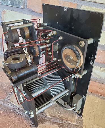
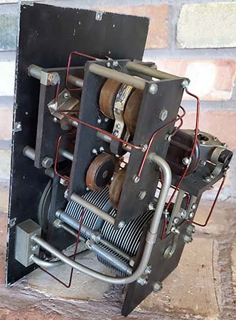
SE-1387 - better view of Oscillator coils and the moveable shielded Coupling coil.

The RECEIVER terminals route the SE-143 RF Tuner output (RA) directly to the GRID INPUT of the SE-1834's RF amplifiers. The SE-1387 (oscillator) output is from the variable coupling coil inside the unit that is connected in series between the SE-143's RE terminal and the lower AMPLIFIER terminal that connects through an adjustable wire-wound resistance to the B- connections within SE-1834, the STABILIZER control (this is an "implied" connection based on the terminal layout.) The Coupling Coil adjustment should be placed so that the letters on the COUPLING control nomenclature matches the letter of the tuning range selected. From that setting of the COUPLING, the output can be adjusted by slightly varying the Coupling Coil position to provide sufficient heterodyning to the SE-1834 but to not overwhelm a weak CW signal. In simple terms, the tuned LC from the SE-143 is connected directly to the SE-1834's WE 215-A RF Amplifiers and the RF Driver provides a heterodyne at the received frequency for CW reception from VT, Arc or Alternator transmitters. For Spark or Radiophone reception the SE-1387 could be turned off (turn the INCREASE pot fully CCW - like turning off the BFO.)

Shown in the photo to the right is the "Eaton Circuit Driver" built by Wireless Specialty Apparatus Company. The Eaton Circuit Driver was an Eaton Oscillator to which was added a tube socket, an amp meter, a buzzer and a filament adjustment pot. Like the standard Eaton Oscillator, the Eaton Circuit Driver was connected into the secondary LC of a tuner to provide a constant oscillation that didn't depend on the tuned frequency. The "Undamped" selection would have this device perform as the normal Eaton Oscillator. The "Damped" selection added the buzzer to the circuit, apparently "driven" from the received signal to produce a buzzer-modulated signal for wavemeter calibration purposes. The vacuum tube pictured is probably an Atlantic-Pacific ER or a Moorhead ER. This photo is from "Design Data for Receivers and Transmitters" by Milton B. Sleeper, 1922.


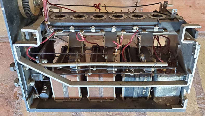
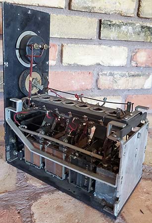
Universal RF-AF Amplifier-Detector SE-1834 - The front three units are four-band RF amplifier coils. Note the wooden framework on RF1 and RF2 coils. The rear two units are Audio interstage xmfrs. The front three tubes are RF amplifiers, then the detector and the rear two tubes are the Audio amplifiers. The RF range switch selects one of four different, broadly tuned RF inductances in each RF transformer (selecting both the primary grid winding and the secondary plate winding.)

The SE-1834 Details - This circuit is correctly referred to as a "Universal RF-AF Amplifier-Detector" consisting, essentially, of a complete receiver minus any selective RF tuning. It uses six WECO 215-A tubes. The three stage RF amplifier uses three broadly-tuned RF transformers with their fixed-frequency ranges selected by the four position front panel switch (WAVELENGTH.) Each RF coil assembly has four RF transformers (primary and secondary windings) that are actually "iron core" transformers. The range of operation is 125M to 30,000M (or 2400kc down to 10kc in four ranges.) The amplified RF output is routed to a grid-leak detector tube that uses a glass grid RC cartridge. At the time, in 1922, it was common for only the grid capacitor to be used and a grid leak resistor wasn't used. If that's the design in the SE-1834, then all four of the glass plug-in cartridges would have been small value capacitors. If the SE-1387 RF Driver/Heterodyne Osc. is used, then the SE-143's Tickler coil doesn't need to be utilized and the strap between the two "TICKLER" terminals is installed. If just the SE-1834 is used, then the TICKLER strap is removed and two wires are installed to connect the SE-143 TICKLER terminals to the SE-1834 TICKLER terminals. The connection allows the SE-1834 Plate voltage to be routed through the 1st AF transformer primary to one of the TICKLER terminals, then to one of the SE-143 TICKLER terminals, through the SE-143 Tickler coil, back to the second SE-143 TICKLER terminal and back to the second SE-1834 TICKLER terminal to the Detector plate. There was a glass tubular small value capacitor installed in clips that connected the interstage transformer side of the TICKLER terminals with the other clip connected to A+/B- to shunt RF off of the interstage transformer primary.


SE-1834 - Note the RF range switch. The meter is 2vdc FS and optimized for the 1.0vdc filaments of the WE 215-A tubes.

The complete setup using the SE-1387/SE-1834 Combo would have SE-143 RF Tuner operating with three stages of broadly-tuned RF Amplification, a grid-leak or C-grid detector with the SE-1387 providing a CW heterodyne oscillator (manually tuned on-frequency heterodyne oscillator) and then two stages of transformer-coupled Audio Amplification. By turning off the SE-1387, the SE-143 operates as a standard TRF receiver and can demodulate signals from spark transmitters or Radiophone signals.

Where the SE-1387/SE-1834 Came From - Fellow LW enthusiast, Dave Sampson, gave me this SE-1387/SE-1834 Combo about six years ago, in August 2020. Dave shipped it from his QTH in Western New York out to Nevada along with a FTC/Mackay RC-123. When I inspected the unit, the first thing I noticed was that it used WE 215-A tubes and all seven tubes were gone. I didn't have any WE 215-A tubes left. I had sold most of my collector tubes,...to a tube collector,...and the WE215-A tubes (five of them) were part of the sale. I did a visual inspection through the two top lids but never took the two units out of the cabinet. That resulted in an assumption that the SE-1387 and SE-1834 were some type of RF amplifier. Not quite six years went by and I then acquired the SE-143 receiver. In some way, I knew that the SE-1387 and SE-1834 required an RF Tuner like the SE-143. That piqued my interest enough to disassemble the unit and see exactly what it was supposed to do.

The Interconnection and Operation - The SE-143 RF Tuner was directly connected to the SE-1834's three stage, RF transformer-coupled RF amplifier by connecting the SE-143 RA and RE terminals to the RECEIVER terminals on the SE-1387. It was mentioned in the SE-143 manual that since the RA wire is a "grid connection" it had to be isolated, as much as possible, from other wires ("not bunched with the other wires" was the terminology used.) However, note that the SE-1387 terminals do provide a grounded SHIELD terminal implying that the RA/RE SE-143 connection should use a shielded cable. Internally, the RECEIVER terminals connect directly to the AMPLIFIER-GRID terminals and are "strapped" to the GRID INPUT of the SE-1834. This allowed the SE-143 a direct connection via its RA terminal to the first RF amplifier grid. The SE-143 Secondary LC ground-return is routed through the pick-up coil in the SE-1387 to allow the heterodyne oscillator to modulate the incoming signal to the SE-1834 RF amplifier grid (if the SE-1387 is powered-up.) Since the heterodyne is modulating the ground-return, there is a wire-wound resistance that's adjustable to "stabilize" the actual heterodyne versus signal ratio. The actual practicality of this connection relies on the oscillator coupling coil having a low enough impedance and that the oscillator has enough pk-pk voltage output to overcome the losses of this type of hook-up. As mentioned, this hook-up is implied by the location of the terminals and, without any documentation, an actual functioning interconnection has to be determined by experimentation using operational equipment. Testing and actual operation has shown that this hook-up works quite well.

The RF amplifiers were broadly tuned via three RF transformers that provided four broadly-tuned ranges. This is essentially also where the incoming tuned radio signal was heterodyned with the SE-1387's variable-coupled oscillator output to allow detecting CW signals from VT, Arc or Alternator transmitters. The output of the 3rd RF amplifier stage was then routed to the detector stage. The output of the detector was routed to a two-stage, transformer-coupled audio amplifier. The audio output was routed to the TEL. terminals. Total gain was controlled by the filament voltage control and by the STABILIZER control. The purpose of the switch RADIO-AUDIO/AUDIO is to allow all filaments to operate in the RADIO/AUDIO position and turns off the filaments to the Detector tube and the two AF amplifier tubes in the AUDIO position allowing just the three RF amplifier tubes to operate (although this seems opposite of the expected function, measuring the continuity confirmed that the detector and audio tube filaments are turned off in the AUDIO position. However, the nomenclature might imply using only the SE-1837 RF amplifiers ahead of the receiver's regenerative detector and audio stages. There's also the possibility of a 1920s vintage modification since it appears that a few wires that should be present, aren't.) The STABILIZER control is a wire wound resistance of the SE-143 RE connection terminal (secondary tuned LC ground return) to the B- line. The FILAMEOSTAT adjusts the filament voltage on the WECO 215-A tubes (set to less than 1vdc fil voltage.) For use of the SE-1387/SE1834 combo, the TICKLER terminals have the strap installed and the AMPLIFIER-GRID INPUT straps are also installed. If just the SE-1834 was used with an SE-143 RF Tuner, it would be possible to remove the TICKLER strap and use the TICKLER connections on the receiver for a regenerative detector. The RA-RE connections on the SE-143 would then be connected to the SE-1834 GRID INPUT directly. Again, these are implied connections. An actual functioning hook-up has to be determined by experimenting with operational equipment. I have operated the SE-143 with the SE-1834 set up as a regenerative detector utilizing the SE-143 Tickler and it functions very well.

There was an SE-1834A version that eliminated the filament voltage meter (shown in two of the vintage B&W photos further below.)

The Western Electric Co. 215-A tube - WECO 215-A tubes, also known as VT-5 or D-80039, are very similar internally to the WD-11 tube. However it's quite probable that the internal design of the later WD-11 that was used in Westinghouse-RCA battery operated Broadcast consumer radios from 1922 up to 1925 was actually based on the 215-A since Westinghouse and AT&T (Western Electric) were cross-licensed in the GE-RCA "Radio Group." The 215-A tube envelope and base are significantly smaller than the WD-11. The tube socket is unique and only fits the 215-A. Filament specs are 1.0vdc at .25A (WD-11 is 1.1vdc at .25A.) If the filament structure is like the WD-11/WD-12, then the 215-A uses an iridium-platinum ribbon that's oxide-coated. The 215-A behaves like a WD-11 in that filament emission takes place at a very low temperature and low current level (much lower than the 1vdc at .25A spec.) Most of the time, the 215-A filament isn't really incandescent at all but the emission is at specifications. In a day when a typical UV-201 tube required 5vdc at 1amp and the pure tungsten filament incandesced like a 5 watt lamp, the 215-A and the WD-11 behaved quite differently with many users unnecessarily increasing the filament current up to the point of filament incandescent visibility with disastrous results (depleting the emitting component of the oxide coating due to excessive heat.) Plate voltage maximum is +100vdc though usually the tubes are operated at +40vdc to +60vdc. The amplification factor is typically about 5 but could go up to 7 or 8 at higher plate voltages and if the tube has good emission. The 215-A tube was only used for a short time and was commonly found in the Western Electric Broadcast Monitoring Superheterodyne Receivers, like the 3-series and 4-series, also other WE BC monitors and apparently in a hearing testing device. Its common use was in the period of 1921 up to about 1928 although there are some indications that the U.S. Navy had some use for 215-A tubes as late as the early-1940s (a 1944 contract.) Although the WD-11, WD-12, WE239A and, the more modern replacement, the RCA 864 all have almost identical specs as far as the tube elements and function, the physical structure of these electrically-similar tubes is completely different. For initial testing, since I sold my collector tubes years ago that had included five good 215-A tubes, I'm going to have to buy seven of them,...ouch! The WE215-A is relatively inexpensive but the WE239-A is astronomically priced (WE tube dealers,...and for an anemic triode with an amplification factor of 5???) WD-11/WD-12 tubes seem to be somewhat fragile because most of the ones I've found had open filaments. I'm going to use the 864 tube for initial testing. It's a little more stoutly built and seems to function okay as a substitute. It's a moderately priced tube but I have several of them that didn't get included in the collector tube sale. I only used the 864 until I actually had a WE 215-A tube to use.

IMPORTANT NOTE on Feb 1944 Contract "NAVY" 215-A tubes: 215-A tubes that are from a USN contract from February 1944, Contract No. N140S21722A, will have "NAVY" stamped in orange paint on the base of the tube. This particular contract was built by Western Electric but the bakelite bases used in this manufacturing run are slightly larger than earlier manufactured tubes. It appears from actually measuring the bases that these 1944 WE versions have bases that are between .005" up to .010" larger in diameter than earlier tubes. These 1944 tubes are a "tight fit" but I've had two of these particular type of 215-A tube that became stuck in the tube socket and couldn't be removed. I couldn't turn the tube so it wouldn't "lock in" and, being wedged in place, I couldn't remove the tube either. Disassembly of the socket was necessary to remove these particular contract 215-A tubes (needless to say, the removal process ruined the tubes.) Perhaps other runs of 215-A sockets other than what I have here (the SE-1387 and SE-1834) might not have this problem. All earlier built WE215-A tubes fit into the sockets easily, just the tubes with the orange "NAVY" on the base have problems with the base fitting into the socket. There's really no good solution to this problem. It would be possible to enlarge the tube socket base hole itself but modifying an original socket just for one contract type of 215A tube isn't a desirable option. Trying to work with the tube base itself would probably end up ruining the tube. Pre-testing the 215-A "NAVY" tube (1944 contract) would be the good solution but probably not practical since purchasing these tubes is almost always an online buy from eBay dealers (I doubt any of the eBay tube dealers would be willing to use dial calipers to actually measure the base diameter - but that would be a practical solution.) I had three of these original boxed 1944 NAVY 215-A tubes,...one fit snuggly but was okay to use. The other two ended up being destroyed because they became "stuck" in the socket.
 

SE-1387 - Circuit Analysis, Testing, Restoration

There are no schematics available for the SE-1387 or the SE-1834. In fact, there's no documentation available, at all. I've had to trace the wiring to see what the circuits were intended to do when interconnected to an RF tuner like the SE-143. The circuit is a grid-leak oscillator with tightly coupled grid and plate coils. The grid coils connect to the variable condenser to allow the LC to function as a frequency adjustment. The range switch is double-function and selects both the correct grid coils and the correct plate coils simultaneously for a specific tuning range. The oscillator output is coupled by an adjustable "pick-up" coil (COUPLING) that is shielded with non-ferrous metal to allow magnetic pick-up only. The "pick up" coil connects in series between the SE-143 secondary LC ground return (lower Receiver terminal) and the lower Amplifier terminal. My analysis that the tuned oscillator is to provide an on-frequency heterodyne for CW reception is based on the increasing use of CW in place of Spark transmissions at the time and how later "Tracking BFO" TRF receivers were designed. Vintage photos helped to actually see how these devices were connected to the SE-143 in particular. However, the final analysis will be to confirm the SE-1387 does function as I think it should. This will require a usable WE 215-A tube. That should provide functionality for the SE-1387 and, with an oscilloscope and a LF-MW receiver, I would be able to see and hear the oscillator output. I've tested all of the coils in the SE-1387 and they all show continuity, so the testing will begin as soon as a good WE215-A is purchased and delivered. I did find a broken solder joint that was on the B+ buss to the plate coils (standard soldering technique of the 1920s using buss wire and "tack soldering" is very prone to breakage,...especially after 100 years on the Planet.) Testing has shown that the implied Filament voltage at the supply was 2.5vdc however, 2vdc is shown on the front panel.  This level allows the INCREASE pot to provide +1.0vdc to a .25A load at the tube filaments with the adjustment at about mid-scale (although the 215-A tube has sufficient emission well-below the +1.0vdc specification.) Also, A+ is connected to B- and both terminals are connected to the shield-chassis front panel ground. For initial testing (before I actually had a 215-A tube,) I used an RCA 864 tube that I connected into the circuit with clip-test leads. Amazingly, this did function exactly as expected but the final testing will have to wait for the 215-A tube to arrive.


The test set-up showing SE-1387 producing a 500kc (600 meters) waveform

The Test Set Up - I used an adjustable Lambda power supply with a voltage range of 0 up to +30vdc at 2.5A. I set the output voltage to +2.5vdc with the wires connecting to - and + FIL BAT terminals. The B+ power supply is an RCA dual bench supply with a range of 0 to +20vdc from each supply. I connected the two supplies in series to have +40vdc B+ with the wires connected to PLATE BAT + and - terminals. The SE-1387 monitoring was provided by the FNIRSI DPOS350P. This is a small, tablet-size, modern piece of multi-function test equipment that runs on a rechargeable battery. I'm using the oscilloscope to monitor waveforms. Also provided by the DPOS350P is the waveform frequency and the P-P voltage and a lot of other parameters of the waveform. Accuracy of the SE-1387 dial is good with 500kc showing slightly off from 600M. The 2.008mHz waveform showed 150M on the SE-1387 dial,...not bad for an oscillator that's over 100 years old.


Looking over the top of the SE-1387 showing the WE215-A tube installed, the 150K grid resistor, the non-ferrous metal shielded pickup coil and the grid-plate coils

Waveform on Range A at 150 meters or 2.008mHz
VP/P=230mv

215-A in SE-1387 - UPDATE: I've run into this problem many times, especially on 1920s tubes. When the 215-A tube arrived, it looked NOS in the original box, but testing the filament continuity showed it was open. Visual examination with magnification revealed that the filament was intact. I re-flowed the solder on the base pins and checked again. This time I had continuity. I did the same re-flowing technique on the grid and plate pins. When the 215-A was installed, at first it didn't oscillate. I increased the filament supply up to +2.5vdc with the INCREASE control about mid-point for just about +1vdc on the filament. The 215-A started to oscillate. I checked ranges A and B with no problems in operation. Subsequent testing confirmed operation on all five ranges. The filament of the 215-A is oxide-coated so as the tube is used it should continue to improve emission. Only use just enough voltage for circuit operation. Excessive filament brilliance will quickly deplete the tube of its ability to emit electrons. I've found that the 215-A tubes will function quite well at about +0.75vdc filament voltage.


Waveform on Range B at 600 meters or 500kc
VP/P=149mv

SE-1834 Circuit Analysis, Testing, Restoration

Testing the functionality of SE-1834 is much more involved in that six WE215-A tubes are required for full operation. Point-to-point DCR testing has shown that both audio interstage transformers have good primary and secondary windings which is very helpful (and, yes, I do use that Triplett VOM for continuity testing as shown in the background of "The Test Set-up" photo above.) The 3rd RF transformer tests good for all four grid windings and for all four plate windings (it appears to be a vintage replacement.) The 2nd RF transformer has all four grid windings showing continuity but two of the plate windings are open (Band 1 and 4.) The 1st RF transformer has all four grid winding showing continuity but three of the plate windings show open (Bands 1, 2 and 3.) All grid windings in the three RF transformers are good (that's 12 grid windings total.) Of the twelve plate windings, five are open and will need to be repaired. Due to the failures in the plate windings involving all four bands, a bypassing of RF1 and RF2 would only leave RF3 in operation,...maybe okay for testing but RF1 and RF2 will have to be repaired for full operation. Due to the "iron core" type of RF transformers and the method of construction, any repairs to the windings will be difficult (but hopefully not impossible.)

All other components of SE-1834 test okay as far as DCR continuity. One broken solder joint was found. It was a buss wire that connected F+ from the STABILIZER adjustable resistor to the 3rd RF transformer grid buss connections. There are four spring-clip type holders that seem to be for glass type cartridges for capacitors (or possibly resistors.) Two are for the Audio tubes and are from the plate to B- which would imply they are small value capacitors. One other spring-clip is connected from the detector grid to the secondary of the 3rd RF transformer. Since there isn't any connection to the detector grid except through this plug-in cartridge it must be the grid-leak (or a grid condenser.) The last spring-clip connects to the TICKLER terminal and to B- indicating this must be another small value capacitor to bypass any RF to B-. I found two, loose in the cabinet, glass capacitors that looked similar to large grid-leak resistors but were marked ".002uf" on the inside. These weren't installed but were wrapped in plastic and had been placed inside the cabinet. These are certainly for the small value capacitors needed. I'm missing a third glass cartridge for the last small value capacitor and a grid-leak resistor although there should be an associated small value capacitor which isn't in the circuitry so it must have been part of the plug-in cartridge. It is possible for the detector to function with just a capacitor however it will perform better with a high value resistor to B- (the resistor can be connected in parallel with the capacitor and "leak" through the secondary winding of the 3rd RF transformer to B-.) It appears that dismounting the tube socket chassis allows access to most of the components. To ease the process of disassembly and reassembly, a wiring assembly drawing (not a schematic) had to be made. Also, close-up photos using a Smart Phone really helps because the photos can be "super-enlarged" on the computer.
RF Transformer Coil Rebuild - Actually, with very little disassembly, the RF transformer coil assemblies can be removed only requiring unsoldering three connections and removing five screws and nuts (straps with threaded holes for the transformer mounting.) I decided to remove and rebuild one RF coil assembly at a time since that will require the least amount of disassembly. With the other coil assemblies remaining in the circuit, I would have a reference for reassembly. The RF Transformer Coils are iron core with about .375" thickness of laminations. Unfortunately, the four coils appear to all share the same laminations. The coils themselves look like the typical audio transformer core only not nearly as wide and with a larger hole in the center of the core. Just to make taking the RF Coil assembly apart even more difficult, where the wires exit the wooden frame, those cavities are filled with sealing wax. It appears that the sealing wax is just in the cavities where the wires exit and not through-out the coils and laminations. Once the sealing wax is melted out, then the RF coil/transformer assembly should come completely apart.

The 1st RF Transformer assembly has three out of the four Plate-to-B+ windings that are open and one Plate-to-B+ winding is okay. All Grid-to-A+/B- windings are okay. I tried a heat-gun to melt out the sealing wax but it isn't a narrow enough application of heat. A small soldering iron works better and is able to apply the heat directly where it's needed. Also, the soldering iron can heat just the individual wires to allow pulling them out of the sealing wax. Once the sealing wax is mostly removed and the wires are not being held by the sealing wax residue, the wooden frame can be removed. This exposes one side of the RF transformer assembly. The same wax melting procedure has to be performed to remove the opposite side wooden frame so that the entire laminations and the four RF cores are accessible.


SE-1834 First RF Transformer Assembly - This is the B+ buss and the A+/B- buss side that's exposed. The other side is the Grid and Plate connections that go to the 4-position Band switch. The removed wooden frame is in the background.

With both wooden frames removed, one can see that the individual coils can slide out of the laminations. Inside the center of each coil is a small iron lamination that's retained using shellac as a gluing agent. This small lamination provides the complete encirclement of each coil with iron laminations but also allows for easy extraction of an individual coil for repair (or replacement back in the 1920s.) The laminations don't have to have physical contact to provide a magnetic flux for proper operation.

Although the RF Transformer coils look similar to audio interstage transformer cores, they aren't the same internally. The photo to the right shows the difference. The primary and secondary windings are spaced about .190" apart but are both wound on the same layer. Each layer builds from the center outward with just a few to several turns for each layer and for both the primary and the secondary. This continues building outward until the correct inductance is reached. Then the hook-up wires are soldered and the finishing wraps put on the coil. Primary winding wires exit on one side and the secondary winding wires exit on the opposite side. That's why when looking at the RF transformer coil, it looked like the wires were exiting from the center and outer edge rather than how audio transformer wires all exit from different layers from center to the outer layer. Winding these RF transformers is easy in one regard, each layer only has a minimal number of turns. On the other hand, one has to do two coils at the same time requiring two spools of magnet wire.

In testing the DCR of the coils and it appears that the turns ratio is probably about 1:1. The only good coil in the 1st RF transformer is the LF coil and the primary and secondary both measure 4400 ohms. If the 1:1 ratio holds true for the other three coils then the next coil DCR is 2200 ohms, then the next coil is 750 ohms DCR and the high frequency coil is 350 ohms DCR. I double-checked these DCR reading by measuring the two remaining RF transformers and the DCR values were consistent at 4400, 2200, 750 and 350 ohms. After a thorough inspection, I think the easiest and best method of repair is to wind entirely new coils. Since both coils are wrapped the same on each layer, that is why the DCR is the same for both the primary and the secondary. However, there are some questions about the DCR involved,...


SE-1834 high frequency 1st RF transformer core removed from the laminations. It's easy to see how the Primary and Secondary windings are on the same layer and that the coils are built from the center of the core out. Also note the size difference with the LF coil being the largest.

Some Math reveals the Impossible - The resistance per foot of 38 gauge magnet wire is .66 ohms. To measure 4400 ohms, the length of wire necessary would be 6,666 feet and since there is a primary and secondary winding that would double to 13,330 feet. The weight of 13,330 feet of 38 gauge copper magnet wire would be around .6 pounds. It's physically IMPOSSIBLE for that much wire to be placed in the core of the largest of the cores and that core itself doesn't weigh even close to half-a-pound. 1922 Federal T&T plug-in RF Transformers were wound with resistance wire that allowed a typical number of turns to the windings to have a much greater DC resistance than expected. I scraped off the enamel coating on the RF transformer core's wire and it was silver color. I measured approximately 1.5 ohms for a 1" length and that would equal 18 ohms per foot. For 38 gauge resistance wire this is fairly close to the description of 38 gauge Ni-Chrome wire which is 12 ohms per foot (I measured the wire diameter using a dial caliper, so there could be a slight physical error since I probably was also measuring the insulation material. Maybe the wire is actually 40 gauge.) This makes the amount of wire necessary much more believable. 4400 ohms DCR would take 366 ft of wire and that's for the largest coil (732 feet for both the primary and secondary total.) For the highest frequency coil (smallest) that would take just 29 feet of wire or 58 feet total for the primary and secondary. The MAJOR problem is virtually no Ni-Chrome wire is available with an enamel-type (Foamvar now) of insulated coating. Insulated Ni-Chrome is a specialty type of resistance wire and priced well-into the stratosphere (how about $750 for 100 feet! That would be $4000 for the amount I need! It must be the cost of Foamvar.) I did find a cheap source of 38 gauge insulated Ni-Chrome wire but it was in the Ukraine and on eBay. The bargain-priced Ukrainian Ni-Chrome is $25 for 25 meters and I need 175 meters total (575 feet) and that prices out at about $175 and that includes shipping but Customs duty or tariffs and battle zones are an unknown let alone what the delivery time would be. Also, I have to contact the seller to see if he can actually supply 175 meters (7x of what he's selling.)

Not the Best Solution, but a Working Solution - Essentially, the need for insulated Ni-Chrome for the RF coils and its "specialty" status means another, hopefully temporary, solution is necessary. Luckily, the 3rd RF transformer is completely intact and can be used. I can disconnect the grid input wire from the 1st RF Amplifier tube and disconnect the 3rd RF Amplifier grid wire (that is coming from the 2nd RF Amplifier.) Then the grid wire that had been connected to the 1st RF Amp tube can be routed to the 3rd RF Amp tube. This would allow the SE-1834 to be used as a broadband four position single RF Amplifier stage, detector, heterodyne oscillator and two stage Audio Amplifier. This would end up with the SE-143 operating as a five-tube TRF receiver including the Heterodyne Oscillator (which is better than not operating at all.)

If the bargain-priced 38 gauge insulated-coated Ni-Chrome wire works out then I can then go ahead and restore the 1st and 2nd RF transformer assemblies. Incidentally, I've come up with a method that would only require rewinding the open plate (primary) windings. The core could actually be bisected down the middle, separating the primary from the secondary. Then a new primary wound with the Ni-Chrome wire and that completed primary core (half) could be "grafted" back onto the secondary part of the core. This method also divides the amount of Ni-Chrome wire needed in half, that is, compared to if the core was entirely rewound (both primary and secondary windings.) The requirement of 575 feet (175 meters) of wire is based on using this solution.

Implementing the SE-1834 Circuit Changes - All of the circuit changes implemented are easily reversible. I reassembled the 1st RF Transformer but didn't bother connecting up each of the cores. They are present, except for the highest frequency core, inside the assembly. All four of the cores will be available for rebuilding when the correct type of Ni-Chrome wire is found. I then reinstalled the 1st RF transformer assembly back into the chassis of SE-1834. I didn't bother with fixing the band switch contact arms for RF1 and RF2 since they aren't going to be operational anyway. I did realign the contact arms for RF3 so they make proper contact with operation of the band switch. Since RF1 was disconnected internally, I removed the B+ going the RF1. RF2 wasn't taken apart so I left the B+ connected there. I removed the flexible wire from RF3 grid and the flexible wire from RF1 grid. I taped the end of the RF1 grid wire. I installed a 2" flexible wire extension to the grid wire that comes from the RA input and soldered that wire to RF3 grid. That will have the RF tuned signal from the SE-143 connected to RF3 grid. This completed the circuit changes necessary for operation.

Testing - I hooked up +2vdc to FIL+ and FIL- at which point the meter indicated FS +2vdc regardless of the filament adjustment pot (no tubes, no load.) I checked that I had +2vdc at all of the tube socket filament contacts. Next, I connected +40vdc to the B+ and B- and tested the tube socket plate contacts. The detector plate didn't have B+. The problem was caused by the very dirty and partially oxidized TICKLER terminals and the shorting strap. I cleaned all the metal parts with a brass bristle brush. When reassembled, I had detector plate voltage at the tube socket. I installed two 215-A tubes in the AF1 and AF2 amplifier positions. I connected a set of Baldwin Type C 'phones to the TEL terminals. I connected an audio signal generator set to 400hz to the plate of the detector tube socket (no detector tube installed.) This connection placed the audio signal going through the primary of the first AF interstage transformer. With +2vdc FIL and +40vdc B+ applied, I heard the 400hz signal coming through the Baldwin 'phones. This test showed that the audio section is working correctly.

To test the detector and RF amplifier requires a modulated RF signal. I first needed to make up a grid-leak and a small value capacitor for the two clip connections for the detector "plug-ins." I installed two more 215-A tubes in the Detector socket and in the 3rd RF Amplifier socket. I used the HP606B to apply a 500kc (600M) RF signal modulated with 400hz to the Grid input terminal of the SE-1834. Voltage was applied and with the SE-1834 set on the 250M to 750M band, I heard the HP606B coming through the Baldwin 'phones. I tried the other three ranges and adjusted the HP606B as needed. All four bands worked.

I moved the SE-1834 and the power supplies to the ham shack where the SE-143 was set up. I connected the SE-143 RA to top INPUT terminal on the SE-1387 and SE-143 RE to the SE-1384 bottom INPUT terminal. I shorted the SE-143 TICKLER terminals and placed the TICKLER COUPLING at MIN. I had the SE-143 set to 630kc (KPLY-Reno) so I set the SE-1834 band switch to 250M-750M and applied voltage. KPLY came in so strong, the signal was somewhat distorted. I made a few adjustments to both the SE-143 and the SE-1834 and that got the signal strong without distortion. I tried a few other daytime AM-BC stations and all were received easily. Next, I removed the jumper from the SE-143 TICKLER terminals and the shorting strap from the TICKLER terminals on the SE-1834. I used two wires to interconnect the TICKLER coil to the setup. Although there was an increase in signal, I couldn't get the detector to oscillate. The connection of RE from the SE-143 is to B-/A+ through the SE-1387 Coupling Coil and the SE-1834 STABILIZER variable resistance. I had the SE-143 connected RE to B-/A+ in my first setup and I couldn't get the UX-201A tube to oscillate either. Only when I connect RE directly to the A- terminal will the SE-143 detector oscillate. There's no way to make that connection using the terminals as marked on the SE-1834 BUT if I hook-up the SE-1387 Heterodyne Oscillator, I should be able to have a tunable heterodyne available. The gain of this setup with just one RF amplifier is certainly less than what it was originally (less selectivity also.) Still, it will drive a horn speaker to room volume on AM-BC stations and is extremely LOUD on 'phones. In fact, the AM-BC stations are too loud for 'phones so I set up the WE 10-D horn speaker if AM-BC is going to be tuned (only for test purposes.)


Using the SE-143 Receiver with the SE-1387 Heterodyne Oscillator and the SE-1834 RF Amplifier-Detector-2 stage Audio Amplifier

The key to getting the SE-1387 and SE-1834 combo working with the SE-143 is experimentation. Since there's absolutely no documentation on the SE-1387 or the SE-1834, I've had to rely on my circuit analysis, the implied connections from the arrangement of the terminals and one vintage photograph (the 1925 USN Shipboard Radio Room photo below) to theorize how the entire setup would interconnect and function. Then experimentation was necessary to see if theory could actually result in a complete working apparatus. Luckily, it did.

Performance of the SE-143 with the SE-1387/SE1834 "Combo" - The SE-1387 RF Driver provides a very strong heterodyne signal that requires reducing the SE-1387 COUPLING. Using the letters on the scale will provide the strongest response from the oscillator which is usually "over-powering." Reducing the COUPLING will slightly detune the oscillator frequency which will reduce the pk-pk output level and then, of course, the SE-1387 tuning dial can be used to place the heterodyne as desired. Reducing the SE-143 INDUCTIVE COUPLING will also help in reducing the signal level if necessary and this will also increase selectivity.

TESTING - To simulate an LF CW signal, I connected the HP606B to a 50' wire laying on the floor. I set the frequency to 300kc or 1000M with the amplitude set to 300mv rms. The SE-143 was picking up this signal using the outdoor 250' end-fed wire antenna. Audio output was to the WE 10-D horn speaker. The carrier plus heterodyne was easily found and tuned for maximum. I keyed the output of the HP606B to see how true CW would have sounded and it was pretty nice. Stability of the heterodyne note is pretty good with maybe a few hz variance every so often. The heterodyne note quality was very good. Copying a true CW signal would have been easy.

Also tested reception over the air of Loran-E 100kc and WWVB 60kc. This required changing ranges on the SE-1387/SE1834 and the SE-143. Heterodyne tuning on Loran-E and WWVB along with over the air reception demonstrated that the combination was working on all tuning ranges. Although all of the "below 500kc signals" mentioned were audible through the WE-10-D horn, it was much better copy on these signals when using 'phones however any AM-BC stations tuned were "too loud" for 'phones (put the 'phones on the cheekbone in front of the ears for strong signals.) The WE215-A tubes seem to work best at about 75% of specified filament voltage, about 0.75vdc results in good performance.
 

OPERATIONAL NOTES - PHOTO RIGHT: The photo shows the SE-143 with the "Combo" tuned to and actually receiving WWVB 60kc or 5000M. The filament supply is set to +2.5vdc and, with the Filament adjustments on the "Combo," the five WE215-A tubes are drawing about 900mA (at their rated .25A each the total current would be 1.25A.) The FILAMENT meter on the SE-1834 reads +0.72vdc. The Plate supply meters each show FS at +20vdc for a total of +40vdc plate voltage. Note that Antenna lead wire is connected to the PRI LOAD COIL terminal and the ANT is jumped to GR. This connects the Primary LC for parallel tuning that allows actually tuning the Primary LC to resonance (below 100kc) for tremendous signal strength. Also note that, since the TICKLER isn't utilized in this hook-up, it's shunted and set to MIN. coupling. Antenna is the 250' End-Fed wire and the 'phones are Baldwin Navy Type-C. Since I was still in the "test-experiment" mode, I was still using clip-on test leads. These have been replaced with an authentic harness built with vintage wire.

Performance of the SE-1834 as a Regenerative Detector with RF Amplifier and two stages of Audio Amplification - The TICKLER connection just using the SE-1834 would require a somewhat different hook-up to function with the SE-143. The SE-143 RE terminal needs to be connected directly to the A- on the power supply. I think that if the setup desired (back in the 1920s) was for a regenerative detector, then this slight deviation from the implied "hook-up" would be necessary. If there was a manual, maybe it did cover this hook-up when using the SE-143 and the SE-1834 as an RF Amplifier-Regenerative Detector type setup. Since this hook-up doesn't use the SE-1387, the COUPLING coil isn't in the RE wiring so connecting the SE-143 RE directly to A- won't be a problem. SE-143 TICKLER terminals are connected to the SE-1834 TICKLER terminals after the strap is removed. The two straps between the SE-1387 and SE-1834 terminals also have to be removed. The SE-143 RA terminal is connected directly to the SE-1834 GRID terminal. Like any regenerative detector, the SE-1834's WE 215-A tube ability to oscillate depends on the plate voltage and the filament voltage plus the position of the SE-143 TICKLER coil. All of these settings will interact along with the INDUCTIVE COUPLING setting, the tuned frequency and the type of antenna used. When everything is adjusted correctly, the received gain and sensitivity are incredible. Well, after all, it's a regenerative detector with an RF amplifier ahead of it and two stages of audio amplification behind it.

Comparison of the Homebrew D-A to the SE-1387/SE1834 Combination Setup - While this homebrew regenerative detector and 2-stage amplifier works fine and I'm sure many MW signals could be found during the LW season at night, the regenerative detector is very fussy to adjust and requires keeping both the Primary LC and the Secondary LC tuned exactly to maintain "Critical Coupling" for maximum sensitivity. There's a lot of control manipulation required with a regenerative detector. I've tuned in everything from AM-BC down to WWVB on 60kc. Also, the MSK signal on 70kc and many carriers between 60kc and 70kc. Of course, Loran-E 100kc. All audio reproduction was using a Western Electric 10-D horn speaker. Tuning in low power stations like NDBs requires using headphones for audio reproducers. While all strong signal stations can be tuned in and received over the horn speaker using the homebrew D-A, the SE-1387/SE-1834 combo is superior for reception with much better stability and no interaction. This is because the detector isn't regenerative, it's just a standard grid-leak detector. The SE-1387 provides the heterodyne necessary for CW reception and the RF amplifier combined with the two-stage AF amplifier is pretty hard to beat.

VLF Experiment tunes to NLK 24.8kc - I connected a 1000 turn honeycomb coil to the PRI LOAD COIL after undoing the shunt. I connected a 600 turn honeycomb coil to the SEC LOAD COIL after undoing its shunt. Since I was using the SE-1387 heterodyne oscillator and SE-1834 as the RF amp, detector with 2 stage AF amp, a tickler coil wasn't necessary. I just set the two coils next to each other on top of the receiver with a slight angle between the coils for coupling purposes. I used clip-on test leads for the connections. This was just a test to see if the loading coils would allow tuning to the VLF part of the spectrum. I set the heterodyne oscillator to 15,000M or about 20kc. The USN Sub-Comm MSK stations operate from 19kc up to 25kc. I set the SE-143 inductance switches to maximum L. I had the Antenna connected for parallel LC on the Primary tuning. I switched on the power supplies to operate the SE-1387 and SE-1834. There isn't any calibration on the Secondary tuning for wavelengths below 6000M but the blank area above scale 6 could have been used for pencil notations when using loading coils. I could hear the heterodyne oscillator after I tuned the SE-143 to about mid-scale. After some primary and secondary tuning with some adjustment of the loading coil positions, I could hear the familiar sound of NLK 24.8kc from Jim Creek, Washington. NLK transmits a Minimum-Shift Keying or MSK type of signal that produces a "warbling" sound if there is an oscillating heterodyne to modulate the signal for audibility. NLK can run up to 1.25 million watts to a double horizontal "W" antenna that has its ten 5000' horizontal runs across a valley between two mountain sides in Central Washington. NLK produces a formidable signal in the Western USA. With a better setup for the loading coils I'm sure this type of longwave reception will become a much easier operation,...this was just an "clip-lead" type of experiment to see if VLF operation was possible.

Building a Replica Remler Duo-Lateral Honeycomb Coil Mount - Photo Right - I based the design of this Duo-Lateral coil mount on the one that can be seen in the U.S. Navy Shipboard Radio Room photo (in next section below) and on the photo of the Remler Duo-Lateral coil mount that's shown in the old 1970s Morgan McMahon book "Vintage Radio." I searched through my stash of vintage bakelite material to find appropriate thickness pieces. The vertical piece is .375" thick bakelite and the bottom is .250" bakelite. The vertical piece is mounted with large hex threaded (10-32) stand-offs (although the original Remler stand had round stand-offs.) The hex stand-offs were already nickel-plated and were vintage. For the actual coil mounts, I had a box of Remler Honeycomb coil parts and the box contained all of the pieces I needed to have a stationary Secondary Coil in the middle position and a "swinging" Primary Coil on the left and a "swinging" Tickler Coil on the right. The Remler coil mounts that "swing" have a hole through the side of the bakelite mount for mounting a round metal rod that's bent forward to act as an arm that allows moving the "swinging" coils with a minimal amount of hand-capacitance effect.

Since the low frequency coils are quite large (4" diameter) and fairly heavy, the vertical bakelite piece for the coil mounts has to set far back on the bottom bakelite piece to allow the front-heavy coils to be supported in a mechanically stable manner. The original Remler mounts didn't do this and were intended to be physically secured to whatever they were placed on with screws. I didn't want to do that type of mounting so I made the bottom deeper to allow the vertical piece to set back and have the coil weight supported by the extension of the bottom piece further forward. The wires hook up in the back of the vertical mount and are routed forward around the sides to connect to the SE-143 terminals. This hook-up can be seen in the USN Shipboard Radio Room photo below. I had to make the lever-arms for swinging the Primary and Tickler coils. I used 3/16" steel rods 8" long. I tapped the holes in the coil sockets and threaded the ends of the rods. I installed the rods and marked them for bending. The rods were unscrewed, bent and then reinstalled. I used 1920s vintage knobs for the ends of the rods. Next, the six wires were installed. These were vintage wires but they were all black insulation which is how the hookup wires appear in the USN Shipboard Radio Room photo. The wire ends were stripped and tinned for the best connections.


The SE-143 with SE-1387/SE1834 "Combo" and Long Wave Duo-Lateral Loading Coils on top.
This setup easily receives NLK 24.8kc, NAA 24.0kc and NPM 21.4kc USN Sub-Comm stations. The station, as photographed above, is set up on 750M or 404kc and is receiving the NDB MOG 404kc in Montegue, California. The Filament Voltage meter shows +.78vdc with the current drawn at about 1A as shown on the Lambda current meter (1A FS.) The RCA dual supplies show +20vdc each for +40vdc plate voltage. The reproducer is a Western Electric 10-D horn speaker. Normally, for NDBs, 'phones are used as reproducers but MOG is a fairly close NDB and usually one of the strongest received. The
Primary LC is connected in-series since the tuned frequency is 404kc.

Using Longwave Loading Coils to Tune VLF - The photo to the left shows the SE-143 with the SE-1387/SE-1834 "Combo" and the replica Remler Duo-Lateral LW Coil Mount on top of the receiver. The coils are 1000 turn Primary, 600 turn Secondary and a 250 turn Tickler that isn't used unless the detector is reconfigured to be regenerative. I could easily tune in NLK 24.8kc and the signal was very loud. I tuned just a bit lower in frequency which requires keeping the Primary condenser tuned, to receive NAA 24.0kc in Cutler, Maine. NAA can run up to 2 million watts to an immense dual Trideco-umbrella antenna array but NAA usually runs about 1 million watts (500KW to each Trideco.) NAA wasn't as strong as NLK but it was still a strong signal that was easy to tune in.  I was able to tune in NPM 21.4kc from Hawaii. However, without a marker signal for reference, it's difficult to tell exactly which USN station is being received. Usually, NLK would be strongest, then NPM followed by NAA. NWC 19.8kc in Exmouth, Australia is only a moderate strength signal and NML 25.2kc in LaMoure, North Dakota doesn't seem to transmit as often as the other USN stations.

Using a function generator to provide a frequency marker, I was able to confirm that NLK, NAA and NPM could all be tuned and received over the air. Also, using the function generator, I could actually test the tuning range using the LW Loading Coils. The best frequency coverage was using the 600 turn coil for the Secondary and the 1000 turn coil for the Primary. The highest frequency that I could actually receive an identifiable signal was WWVB 60kc (10KW - Ft. Collins, Colorado.) The lowest frequency I was able to tune and receive an identifiable signal was NPM at 21.4kc (550KW to twin 1503' high ground-isolated towers supporting top-fed dual radiators running down to the helix house - Lualualai, Hawaii.) I think a more precise coverage would probably result in having a 750 turn coil for the Secondary, which would probably result in 50kc to 15kc tuning (just a guess.) The 1000 turn coil works okay for the Primary but another 750 turn coil would move the Primary tuning more to the center of the tuning range. These large 4" diameter honeycomb LW coils are difficult to find, so I'm still in the search mode for a 700 to 800 turn coil,...or maybe two.

NOTE 1: On using the Heterodyne Oscillator,...like any beat frequency oscillator, it's easily possible to use the oscillator to adjust the apparent received frequency. At high frequencies, 1kc of heterodyne only seems to change the CW beat note,...perceived as an audio effect. At VLF, 1kc of heterodyne action can substantially effect the tuning, changing for example 24kc combined with a heterodyne to produce a 1kc beat note can move the apparent received frequency to 25kc. When NAA, NLK and NML are all separated by less than 1kc, the Heterodyne Oscillator has to be carefully adjusted and monitored. Tuning in stations with the heterodyne oscillator turned off will result in more accurate tuning but often the desired station can't be heard unless there's a beat note present.

NOTE 2: One of the best improvements was to eliminate all of the clip-lead connections. I've built an authentic harness based on the harness shown in the photograph of the USN Radio Room from 1925, the fourth photo in the next section. The wires are all black rubber insulation and the wires are 14 gauge stranded. These are true vintage wires that are in excellent condition but their age imparts the correct "look" for the harness. I had to change the routing of the harness wires somewhat (when compared to the photograph) since I was using different types of equipment in somewhat different locations on top of the SE-143. However, I maintained the "vintage style" for the harness. Performance is now very stable and excellent.

NOTE 3: Using the Homebrew D-A with Regen Det and the LW Coil setup, I was able to receive NWC 19.8kc Exmouth, Australia. I substituted the useless 1500 turn Tickler coil with a 250 turn Tickler coil (4th largest I have) and it worked surprisingly well.

NOTE 4: Can a Shielded-Magnetic Loop Antenna like the Pixel Loop be used with the SE-143? There are a couple of benefits to using the Pixel Loop or any type of shielded-magnetic loop. First, the Pixel Loop has some immunity to RFI-type noise. Second, it can be directional and can also be used to "null" directional interference. But how to couple the 75 ohm output impedance (Z) of the Pixel Loop to the SE-143 Hi-Z wire antenna expectations? I used an "un-un" which is a special type of "unbalanced to unbalanced" type of impedance transformer. The one I used was for operating an end-fed wire (Hi-Z) to a modern receiver Antenna input (Lo-Z.) Surprisingly, it worked really quite well hooked-up backwards. I connected the 75Z side to the Pixel Loop and then connected the Hi-Z EFW single wing-nut terminal using a 36" 18ga stranded wire to the ANT terminal on the SE-143 with the GN terminal grounded. I had the SE-143 tuned to about 340 meters with the Primary LC in series. I turned on the SE-143 Combo and the Pixel Loop LNA and KKOH 780kc Reno, Nevada was coming in very strong. I tuned to KPLY 630kc Reno, KHOG 980kc Fallon, KFOY 1060kc Sparks and KCMY 1300kc Carson City. The first thing noticed was signals were strong and easy to tune. Selectivity was excellent. But, the Primary LC tuning was rather broad so I changed the Primary LC to parallel tuned and that improved the tuning so that a peak response was easy to find. I was listening on the Western Electric 10-D horn speaker. These "un-un" type of matching transformers are sold as an "End-Fed Wire Antenna Matching Transformer." There are various ratios available but 9:1 is very common and works fine in this application. The Pixel Loop has a bandwidth of 30mc down to 150kc and can be used at even lower frequencies (spec'd to 150kc though.) There is a W6LVP shielded-magnetic loop also available with similar specifications and priced at half of what the Pixel Loop sells for. Generally, by 100kc and lower frequencies, a wire antenna will perform better.


NDB Log for SE-143 with SE-1387 and SE-1834 Combo plus Long Wave Loading Coils

Sept 3, 2026  0530hrs to 0550hrs PDT

MW 408kc - Moses Lake, WA
MOG 404kc - Montegue, CA
DC 326kc - Princeton, BC, CAN

Severe QRN for first 7 or 8 minutes, then clear reception. These three NDBs were quite strong but only a few non-identified carriers heard between MOG 404kc and DC 326kc. It's still early for LW reception,...not Fall yet.

Pri LC in Series. LW Coils shunted. Antenna - 250' wire. Ground - house plus counterpoise. Baldwin Type-C 'phones


Vintage Photos of SE-143 and SE-1420 Setups with Various "add-ons"

Vintage photographs of early radio stations are always interesting but they are even more interesting if the equipment in the photo can be identified. I've provided as much information as I can as far as recognizable equipment, the frequencies being used and the various "hook-ups" being used. The first photograph is an SE-143-based station at NAA. It's an actual working environment and with the radio operator present. This "at work" photo was a real impromptu shot that is slightly over-exposed and the operator moved his head during the exposure. The second photo is an "equipment only" shot but the important aspect is that the photo is dated and it tells exactly where it was taken, NPX in San Pedro. It's an extremely large photo with lots of detail. The third photo is also of another listening station at NPX that used an SE-1420 receiver and SE-1000 amplifier. The fourth photo is a very informative photo of a USN shipboard radio room that has an SE-143 with a lot of "add-on" equipment shown. All of the various hook-ups are described in the text. This photo was taken with an excellent camera lens, it's superbly focused and, when the original is enlarged, the year on the calendar on the wall can be read. The fifth photo shows a "look-alike" SE-143 with a Heterodyne Oscillator hookup that being operated by Paul Sollenberger from the U.S. Naval Observatory. The last photo shows an SE-1420 receiver with some various "add-ons." This shot was probably intended to show the type of equipment being used at NAA at the time of the photo. It's a lot of nicely focused gear and when the original is enlarged the data plates on the equipment can be read.

U.S. Naval Station NAA - Ft. Myer-Arlington, Virginia
SE-143, SE-1071, SE-1000 Station

The photo to the left shows a standard SE-143 set up with the SE-1071 Audion Control Box and the SE-1000 Two-Stage Audio Amplifier. These two accessories were the most commonly used accessories for the SE-143, especially towards the end of WWI and immediately after. On the right side of the table is another SE-1000 and SE-1071. The LW Loading Coils are quite large in this setup. These coils appear to be "single layer" wound coils rather than "bank wound" or "honeycomb" coils which would be noticeably smaller in size. These LW Loading Coils have a set of tap switches in front of the coil to allow selecting various taps on both the primary and secondary. It's difficult to tell if the coupling can be changed but the reduced size of the upper coil seems to imply that it can slide into the lower coil and therefore increase the coupling, although there's no apparent method that can be seen for changing the position of the smaller coil. The large dual coil assembly mounted to the wall is probably an antenna coupler. The lower area under the desk riser appears to have what looks like individual variable condensers but it's unknown exactly what their function would have been. Note that the SE-143 is tuned to a rather high frequency. It looks like about 400kc. This is a "non-posed" photo since the radio op moved his head during the exposure. Note the over-exposed ceiling lamp. Even though the lighting and focus aren't very good, this is an incredibly valuable historical document showing how radio equipment was set-up post-WWI.

Photo date is probably about 1920. At that time, the eagle on the left arm indicated a petty officer in a specialty section, which RADIO would have probably been considered. This photo is all over the Internet and on eBay but I got this copy from navy-radio.com although I did crop and photoshop it.

NOTE: Navy Radio Station NAA was built in 1912. The station house is still used today by the Navy for administration work. The incredible 600 ft tower that was flanked by two 425 ft towers (called The Three Sisters) were razed in 1941 due to their proximity to the Washington D.C. airport. Prior to the razing, all radio equipment and communication duties were moved to USN Station NSS at Annapolis, Maryland

U.S. Naval Radio Station NPX - San Pedro, California  -  June 1920
SE-143, SE-1071, SE-1000 - Control Station

The important aspect of this great photograph is that it's dated and indicates exactly where the equipment is set up. Obviously, the receiver is an example of the later SE-143 receivers. Note that the CRYSTAL-AUDION switch now has a third position, SEND. In addition to the third SEND position, the switch positions of CRYSTAL and AUDION have be exchanged (it's possible that this variation could be typical for Wireless Specialty Apparatus IP-500 builds.) Also, note that the buzzer push button is not the pearl button type but a different type with a black push button. The original photograph is very large (5000x5000mp) and that allows seeing all of the pencil marks on the dials and on the panel of the receiver (a lot of 'em.) Note that the INDUCTIVE COUPLING is at 100 while the TICKLER COUPLING is almost at minimum. The SECONDARY INDUCTANCE is on position 3 covering about 4000 meters to beyond 1350 meters or about 75kc to above 225kc up to about 300kc. The Secondary LC dial is set to the highest frequency possible on position 3 or around 300kc. The Primary LC is hooked up for series LC tuning and no loading coils are used.

Along with the SE-143 is the SE-1071 Audion Control Box with a Crystal Detector stand on top. Note that the Crystal Detector is connected to the CRYSTAL terminals on the receiver although the receiver is set to "AUDION" on the detector selector switch. Also, note the bent connection straps that allows the SE-143 to set in the corner of the table while the SE-1071 is against the wall. Next to the SE-1071 is the SE-1000 2-stage Audio Amplifier. It's position on the table next to the SE-1071 shows just how small the SE-1000 was. Interesting to see that nearly all of the wired connections come through the table top and the holes are grommet-lined. Telegraph hand keys, line relays with ceramic switches and then a sounder with resonator stand are to the right. Note that the paper on the wall above the hand keys is a list of the "Q" codes. Under the clip-held papers is a list of Morse code characters. This great photo is from a collection of 20 very large photos of NPX taken mostly in June 1920. I've cropped and compressed these two photos here but the full size photos can be viewed "large and not compressed" on: www.navy-radio.com  

U.S. Naval Radio Station NPX - San Pedro, California - June 1920
SE-1420, SE-1000 - Control Station

This is another photo from the collection of 20 San Pedro photographs dating from 1919 up into mid-1920 that are on the www.navy-radio.com website. This radio setup was at the other side of the room from the SE-143 station. The receiver is the Wireless Specialty Apparatus Co. version of the SE-1420. This receiver had its own onboard VT regenerative detector so it didn't require the SE-1071 Audion Control Box. However, the station is equipped with the SE-1000 2-stage Audio Amplifier. All connections to both the receiver and the amplifier are routed through the table top using grommet-lined holes. As with the SE-143 receiver at the station shown above, this SE-1420 has pencil marks and dial smudges galore. The receiver is powered up (the meter indicates filament voltage is present) and it's tuned to Secondary Inductance position 4 at letter designation "M" which was 900 meters or about 330kc. The wire antenna lead appears to be routed up the wall with at least one visible ceramic insulator. The 'phones appear to be Western Electric 509-W types. Once again, telegraph hand keys, line relays, ceramic switches and a sounder mounted in a resonator box. The typewriter isn't a "mill" because it only has nine keys on the upper row of keys and the "mill" typewriters had ten keys on the upper row.

In examining these photos, it looks like there was at least one other SE-1420 + SE-1000 station that had the SE-1000 on the left side of the SE-1420. That station was just to the right of the SE-143 station but out of the frame of the SE-143 photo. The station shown in this photo to the right was across the room opposite of where the SE-143 was set up. This indicates that at least three receiving stations were set up at NPX in June 1920. Also, it appears that a radio transmitter wasn't at the station,...at least, if there was one, it wasn't photographed. I suspect that NPX was a "receive-only" station that the USN referred to as a "Control Station." It looks like incoming radio messages were copied and then relayed via landline telegraphy to another USN facility.

U.S. Navy Shipboard Radio Room - ca. 1925
SE-143 Receiver, SE-1372 Heterodyne Osc., LW coils and SE-1834A RF amp/Det/AF amp

The photo to the right is incredibly detailed and extremely informative. It shows part of a Navy shipboard Radio Room installation (note the open porthole to the upper left of the photo.) This installation is using the SE-143 and on the top left of the receiver is a three-range RF Driver, the SE-1372, then a duo-lateral LF loading coil assembly (looks like a Remler Type) and an SE-1834A (no filament meter so it's the "A" version) on the far right.

Note that the SE-143 is set to "CRYSTAL" on the Detector Switch. It's possible to setup the SE-143 to connect to two different VT signal processing circuits selected by either CRYSTAL or AUDION using the front panel switch on the SE-143. The setup could use AUDION to route the Secondary LC from RA and RE terminals to the Heterodyne Oscillator and through its terminals to the SE-1834A RF amp, Detector and AF amplifier. A second setup could be selected with CRYSTAL with the connections to TEL #75 and DET #81 terminals to access the Secondary LC and then route these wires to the SE-1834A as a RF, Regenerative Detector and AF amplifier (and not using the Heterodyne Oscillator.) The external switches would connect or disconnect the TICKLER terminals on the SE-1834A as needed. In essence, using the CRYSTAL and the AUDION switch allows the SE-143 to work with two different setups, e.g., regenerative detector in one position and non-regenerative detector with heterodyne oscillator in the other position (USN and Maritime regulations would require that a Crystal Detector be available somewhere in the Radio Room.) Another possibility is that the SE-143 receiver is the later version with the AUDION-SEND-CRYSTAL positions and the receiver is actually set to AUDION.

The tuned frequency appears to be fairly high as indicated by the where the Inductance switches are placed. A close look at the SE-143 and it appears that both dial pointers are missing. If the Radio Op has the LW coils in the circuit, the placement of the Inductance switches won't have very much of an effect on the tuning since the LW coils have much more inductance than the SE-143 inductors. Since the LW Loading coil set includes a Tickler coil, one can assume that the SE-1834A is operated as a regenerative detector when operating below 50kc. Note that the SE-1834A has the TICKLER strap pointing up indicating that it's operating as a regenerative detector. That assumption then implies that the SE-1372 Three Band Heterodyne Oscillator doesn't operate below 50kc (the SE-1387 will operate down to 10kc.) Somewhere out of view (possibly to the right and slightly back from the front of the receiver - just the upper corner is visible) should be a switch panel that allowed the Radio Op to select "Series-Parallel" for the Primary LC configuration, switches for the LW Loading Coil setup and a switch to select the SE-1834A Tickler input. These switches could have been in the form of DPDT knife-switches or they could also have been rotational switch knobs and arms that worked with contact buttons. The TELEPHONES terminal wiring would be routed around or through the desk for the terminal board provided for 'phones connection located on the front of desk (easily visible in the full-size photo.)   >>>


This is the most informative photograph for showing the SE-143 and various "add-ons" in detail.

>>>  Incidentally, the transmitter is a Quenched-Gap Spark Transmitter, probably one of the 2KW Navy Standard types. Several companies built these for the Navy, like Wireless Specialty Apparatus Co., Kilbourne-Clark Mfg., RCA, Federal Telegraph Co. and others.

The full-size version of this U.S. Navy photo is the "header photo" at the beginning of this write-up. That larger photo actually shows another USN Officer, the ship's Captain. He's standing behind the radioman (the radioman holds the rank of Lieutenant - note the "lightning bolts" above the two bars indicating "radio." He IS THE Radio Officer on the ship.) On the wall behind the Captain is a calendar. This photo is exceptionally well-focused with an excellent camera lens and, although partially obscured by the Captain, the year on the calendar can be read and is "192-" with the last digit not visible. A believable date for this photo would be around 1925.

Paul Sollenberger - Time Service, U.S. Naval Observatory

Not an SE-143 Receiver, 3-Band Heterodyne Oscillator, Detector-Audio Amplifiers

This is an interesting photo that shows Paul Sollenberger before he became the first civilian Director of Nautical Instruments and Time Service for the U.S. Naval Observatory (became Director in 1928.) He appears to be using radio received "time signals" to check the U.S. Navy Maritime clock that's setting on top of the receiver. The receiver being used is certainly based on the SE-143 but it's missing several key pieces. The Stopping Condenser has been eliminated. The Tickler Coupling control and, more than likely, the Tickler coil and rotating assembly have been eliminated. The buzzer has been moved up towards the center of the panel. This receiver appears to be a later version of the SE-143 that was specifically built for operation using a Tunable Heterodyne Oscillator and external RF-Det-AF amp devices. The SE-1372 Tunable Heterodyne Oscillator is on the right side of the receiver. Also, further to the right are some VT devices, probably the VT detector and two stages of audio amplification (quite a few tubes, an interstage transformer, a large air variable condenser and other unrecognizable components can be seen in the photo.) To copy CW, the Heterodyne Oscillator was necessary. This receiver isn't identified but, interestingly, the New England Museum of Wireless and Steam has an identical receiver in their collection and it also isn't identified. I have two photographs of the receiver in the NEMWS collection with one photo being a very large well-focused picture (taken in-person by W6TOM and forwarded to me.) From that photo it can be seen that the receiver doesn't use the RA-RE nomenclature for the output but uses Grid and Filament instead which seems to imply a later design. No Tickler terminals are present, as would be expected. The terminals on the right side of the receiver aren't for connection to an SE-1071 either, implying a later design. Perhaps the receiver is the elusive SE-143A version. The presence of the SE-1372 dates this photo to sometime after 1922.

While he was Director of Nautical Instruments and Time Service, Paul Sollenberger developed several types of instruments including an extremely accurate quartz-crystal based time instrument for the Naval Observatory that was considered the most accurate time device until Atomic Clocks were developed. Although he retired in 1953, he lived quite a long time after that,...until the age of 103.


Paul Sollenberger using radio time signals for checking the accuracy of a USN clock.  ca. 1925


 USN Station NAA  ca. 1925

 (R to L) SE-1420 Receiver, SE-1372 Three Band RF Heterodyne Oscillator, SE-1597 Loop Antenna Amplifier, SE-1834A RF amplifier/detector/AF amplifier and a Receiving Antenna Coupler (being held by Radioman Chief Petty Officer RMC Gilmour) 

NOTE: As can seen in the photo, none of these devices are interconnected implying that the equipment was probably arranged for the photograph and not necessarily that all of the equipment was "used" together.

U.S. Naval Station NAA - Ft. Myer-Arlington, Virginia  ca: 1925
SE-1420, Heterodyne Osc., Loop Antenna Amplifier, RF Amp/Det/AF Amp and a Large Antenna Coupler

Another setup is shown to the left, from USN station NAA. The receiver on the right side of the photo is the famous SE-1420, a single-tube regenerative detector receiver. Next is the SE-1372, a three band, version of the SE-1387 with less oscillator frequency coverage. The next unit is a Loop Antenna Tuner, the SE-1597. The left most unit is the SE-1834A with the "A" being the version without the filament voltage meter. That's quite a Loose Coupler that RMC Gilmour (RMC = Radioman - Chief Petty Officer) is holding though it's probably an antenna coupler of some sort,...note the similarity to the coupler in the older NAA photo above. A believable date for this photo would be around 1925.    this photo is found in many places on the Internet but I got it from navy-radio.com - I've cropped and compressed.

To use the SE-1834A with the SE-1420 would require setting the Function Switch to "CRYSTAL OR R.F. AMPL." Then connect the upper GRID or RA input terminal on the SE-1834A to the upper CRYSTAL terminal on the SE-1420. Connect the lower GRID terminal to the lower of the two TELEPHONES terminals. This hookup bypasses the SE-1420 detector and only uses the ANT and SEC LC tuners to operate the SE-1834A functioning as a three-stage RF amplifier, detector and two-stage Audio Amplifier. This hookup doesn't operate as a regenerative detector because the SE-1420 didn't provide TICKLER terminals. To provide a heterodyne for CW reception the SE-1372 Three-band Heterodyne Oscillator can be connected by using its RECEIVER terminals connected to the SE-1420 upper CRYSTAL for RA and lower TELEPHONES for RE. The output terminals of the SE-1372 connect to the SE-1834A input. That has the Heterodyne Oscillator in series with the RE line where it can modulate the Secondary LC tuner of the SE-1420. No battery voltages would be required for the SE-1420 since only the Primary and Secondary LC tuners would be used. The antenna used would be connected to the ANT and GND terminals on the SE-1420. Unfortunately, there aren't terminals for a LW Adaptor on the SE-1420, so only the series-connected ANT LC is possible.

The Loop Antenna Tuner probably provided a matching network. Note that the SE-1597 doesn't have any voltage input terminals and that implies that it's a passive device that allowed using a low impedance loop with the SE-1420's fairly high impedance expectations as far as antennas are concerned.

A lot of experimenting was certainly necessary when using these "add-on" pieces of equipment to achieve an actual functioning "upgraded" receiver.


Shipboard Radio Receiving Equipment 1918 to 1927 - Part Two                                 Return to Home-Index


References:

1. Hazeltine, the Professor - by Harold A. Wheeler, SE-1420 origins and history - published in Radio Age, April 1978

2. Radio Manufacturers of the 1920s, Vol 3 -  RCA and Wireless Specialty Apparatus history - by Alan Douglas 1991

3. Westinghouse Type RB, photo of Type RB - by Alan Douglas - published in Radio Age, November 1982

4. Tropical Radio and Telegraph Co., United Fruit Co., National Electrical Supply Co. (NESCO,) International Signaling Co., International Radio Telegraph Co. -  Geo. C. Clark "Radioana," Wikipedia and various other online sources

5. "Keeping the Stars and Strips in the Ether" by Cmdr. Stanford Hooper - RCA-Navy relationship, Creation of RCA by General Electric, Purchase of American Marconi by GE -  from Radio Broadcast - June,1922, - Cmdr. Stanford Hooper and Admiral Bullard were the Navy "Brass" that were sent to General Electric to urge GE to not sell their wireless patents to British Marconi but to form a "Radio Corporation" to keep their wireless patents in American hands.

6. SE-143 Operating Instructions, IP-503 Long Wave Loading Unit - George Sterling's SE-143 section in "The Radio Manual" First Edition actually has quite a bit of information on the SE-143 but be sure to also look at the information on Long Wave loading coils as there's more important information in that section. Also, the IP-503 schematic and instructions are in the 1st and 2nd Editions.

7. IP-501-A Manual, SE-1420 Manual, SE-143 Manual - These manuals are online (free download) at Al Krause's website, www.skywaves.ar88.net  Look under "Communications Receivers - NAVY" - The SE-1420 manual is the Navy Instruction Book and is dated 1919. The IP-501-A manual is dated 1936 and is from RCA and is for the later, Radiomarine version of the receiver. This IP-501-A manual has details on setting "Critical Coupling" that greatly improves MW performance when the detector is oscillating.

8. "The Radio Manual" - by George Sterling, four editions, 1st Ed.-1928, 2nd Ed.-1929, 3rd Ed.-1938, 4th Ed.-1950. 1st Edition has descriptions and operating instructions for SE-143, IP-501/SE-1420, IP-503 Long Wave Loading Unit and information on using LW Loading Coils. The 2nd Edition dropped the SE-143 but has the IP-501/SE-1420. Both the 1st and 2nd Editions included some information and a schematic of the IP-503 Long Wave Loading Unit in the IP-501 section. The IP-501-A isn't covered in any of the Radio Manual editions because Sterling believed that the IP-501/SE-1420 were so similar to the IP-501-A that the information provided was sufficient for radiomen and technicians.

9. "How to Make Commercial Type Radio Apparatus" by Milton B. Sleeper - No. 2 in a series of booklets on radio equipment published in 1922 by The Norman W. Henley Publishing Co., NYC, NY. Excellent artwork for the SE-1420.


NAVY-RADIO.COM
- For the most detailed information and lots of photos of Pre-WWII stations, including many photos of SE-143 and SE-1420 installations and other early Navy gear and on all types and all vintages of Navy radio equipment, radio stations, vintage photographs - go to www.navy-radio.com   Nick England's incredible Navy-Radio website has the most information available - anywhere!
 
 
Henry Rogers ©  Jan 2009   More info added Feb.2009, Apr. 2009,  Corrections to RMCA information Dec 2015, more RMCA corrections and minor edits about LW stations June 2018, minor tweaking of RMCA history and production history of IP-501-A - Dec 2020, Added SE-143 RF Tuner, SE-1387 RF Driver, SE-1834 Universal RF-AF Amplifier - Jul 2026, Changed title to "Shipboard Radio Receiver Equipment 1918-1925" - Jul, 2026, Split into two parts Sept 2026,


Return to Home Index


Radio Boulevard
Western Historic Radio Museum

 Vintage Radio Communication Equipment Rebuilding & Restoration Articles,

 Vintage Radio History and WHRM Radio Photo Galleries

1909 - 1969

- 60 years of Radio Technology -


This website created and maintained by: Henry Rogers - Radio Boulevard, Western Historic Radio Museum © 1997/2026