Radio Boulevard
Western Historic Radio Museum


T-368/URT Military Transmitter

Repairing, Rebuilding and Operation
of a Military "Heavyweight" Classic


T-368 History, AN/GRC-26 History, Circuit Details and Installation Considerations, Different T-368 Versions

Working on the T-368 Decks, Powering Up the T-368, Operating the T-368

Auxiliary Equipment: BC-939A/B, ME-165-G


by: Henry Rogers WA7YBS


T-368 Artwork from TM11-809-10

When it comes to military transmitters the T-368 is a favorite of military radio enthusiast hams for several reasons. It's a brute of a transmitter that can produce over 400 watts of RF carrier output power in the AM mode and over 450 watts in the CW mode - all while being powered by the 115VAC line. Domination of the operating frequency is typical when using a T-368. Many T-368 transmitters are in excellent condition, reconditioned by their new owners to work flawlessly. However, other T-368 transmitters are found in original but abused condition and those transmitters can be loaded with problems. This article gives the prospective "T-3" owner some insight into what to look for in a purchase and for new owners some suggestions on what to do before initial power-up including visual inspections and how to safely troubleshoot problems. Also included are profiles on two popular pieces of T-368 auxiliary equipment that were generally used by the military in T-368 installations. - Henry Rogers,  October 2016
 

T-368/URT  Military Radio Transmitter


 photo above: The artwork for the T-368 as shown in TM-11-809-10.
 

T-368 History - By the early 1950s, the widely-used Signal Corps transmitter, the Hallicrafters BC-610, was rapidly becoming outdated and a modern replacement was needed. The T-368 transmitter was designed to be an updated replacement that would fulfill the military's need for a medium power, continuous-duty transmitter that could be set up for mobile operation from a truck or a portable/mobile communications hut or installed in a building for stationary operation. The design allowed for 400 watts to 450 watts of RF power to be delivered to a various types of wire antennae or to a variety of mobile whip antennae.

It's apparent that Collins Radio had some engineering input (or, at least, some influence) on some of the design of the T-368 since the circuit uses a Collins-type PTO to drive a Collins-design, permeability-tuned Multiplier/Exciter module which in turn drives the RF output tube. Also, a Veeder-Root type of mechanical digital counter is used for the transmitter's frequency readout. The similarities to other Collins' designs, like the T-368's contemporary, the Collins T-195, are apparent. Although the PTO and Exciter sections of the T-368 are very similar to the T-195, the T-368 is not an "auto tuning" type transmitter (like the T-195 is) and it must be manually tuned for proper matching to the antenna load impedance. It's also possible that the Signal Corps merely "borrowed" the ideas and components from Collins and incorporated them into the T-368 design. Although Collins didn't build any of the contracts for T-368 transmitters they certainly supplied the design for the PTO and Exciter. Collins did supply the receivers that were generally used with the T-368 (R-390/URR.)

Several different contractors built T-368 transmitters throughout its production history. While Barker & Williamson (B&W) built some of the first contracts, other companies that had contracts for T-368 transmitters included Stromberg-Carlson, TRW and Bendix.

There were seven "official" T-368 versions produced with minor differences that required different letter suffixes for identification. Generally, each successive letter suffix indicates upgrades to components or circuits that were significant enough to warrant identification of that transmitter "build" as a different version. Besides the "Basic" or non-lettered version, there are lettered versions from A through F. The F-version used ceramic vacuum variable capacitors and SS rectifiers. The letter suffix is placed after "368" (e.g., T-368A/URT.) About 100 T-368 transmitters were converted to SSB by the military and these transmitters use different upper decks and a different final amplifier tube. These SSB versions were later produced and designated as the T-2368.

The T-368 was in service from the early-1950s up into the mid-1970s. Since the primary use by the Army was as a RTTY transmitter, the fact that AM was rapidly being replaced by SSB voice transmissions didn't impact the T-368 very much. The following section illustrates how the T-368 was used for RTTY communications.

AN/GRC-26

Many (probably most) T-368s were used for RTTY communications and were installed in "huts" that were somewhat portable. The huts could be set-up in the field and powered by a trailer-mounted (portable,) gas-driven AC generator. The complete hut and its equipment were designated as AN/GRC-26. These huts were RTTY stations set-up for diversity reception of the incoming RTTY signals and featured two R-390 receivers running with the CV-116 Diversity RTTY Converter. The B&W artwork shown below left is of the AN/GRC-26D inside rear wall. The rack equipment (top to bottom) consists of the CV-116 Diversity RTTY Converter, R-390/URR receiver #1, R-390/URR receiver #2 and the LS-206 rack mount dual speaker. The TTY machines were TT-98 for receive only. The TT-76 was a reperforator-transmitter TTY machine for sending. The AN/GRC-26 also was equipped with the MD-239-GR which was the FSK transmitter modulator. The MD-239 was usually mounted on top of the T-368 next to the BC-939-B Antenna Tuner.  The C-1123 was the control set that routed incoming signals from the CV-116 to the TTY machines. It also selected the proper equipment for transmitting the various modes. The hut was approximately seven feet wide by twelve feet long by about eight feet tall. It was usually mounted on a trailer and towed to field locations. Although RTTY was the primary mode of communications, AM could be used, although usually only in an emergency. Sometimes CW was used to establish communication and then the mode was quickly changed to RTTY.

The GRC-26/T-368 set ups utilized the BC-939-B Antenna Tuner (TN-339/GR) which was essentially a gray-painted version of the tuner that was used with the BC-610 transmitter. The BC-939-B allowed the user to match either a whip antenna or perhaps a "long wire" antenna to the T-368's output. 


photo above
: Mobile Communications Hut part of GRC-26. Front side shows the two whips for diversity receive. The transmitting whip antenna is located on the back side of the hut.

The GRC-26 also included the ME-165G SWR Bridge, Dummy Load and Watt Meter that was installed on the wall of the hut near the transmitter. This device allowed the user to measure Standing Wave Ratio (SWR) while trying to match various antenna loads. Additionally, the user could place a 50 ohm dummy load on the transmitter output. The ME-165G was rated at 200 watts continuous or up to 600 watts intermittent.

A variety of antennae could be utilized. Three verticals and two dipole antennas were included in the auxiliary equipment. Also, 1000 feet of wire was included for building other wire antennae as needed.

Various suffix designations identify differences in the GRC-26 communications capabilities. Most differences were minor and didn't affect over-all operation although the "D" suffix was set-up for crypto operations. Generally, AM voice or CW modes were only used for emergency and all communication was supposed to be by RTTY. However, as mentioned, it was common practice to establish communication using CW and then switch to RTTY.


photo above: The CV-116 Diversity RTTY Converter from the AN/GRC-26


T-368 Circuit Details and Installation Considerations

Circuit Details  - The T-368 uses a modular unit called the Exciter that consists of a PTO (permeability-tuned oscillator,) a permeability-tuned Frequency Multiplier section and a permeability-tuned RF Output Section. A mechanical-digital Veeder-Root frequency readout is an integral part of the Multiplier/Exciter unit. The Exciter RF output tube is a type-6000 which provides sufficient power to drive the RF PA output tube which is a 4-400A. The output network is a Pi-L using Jennings vacuum variable capacitors for tuning and loading. The Speech Amplifier is module that is mounted on the Modulator chassis. The Speech Amplifier provides a dual input for either a Carbon mike or for a 600Z ohm audio line. The output of the Speech Amplifier is sufficient to drive the Modulator tubes, a pair of 4-125s. The power supply provides all of the required voltages and uses 3B28 rectifiers for the +HV and 5R4GWB rectifiers for the +LV. The cabinet contains the wiring harness and the Antenna Relay module along with the cabinet blower. There is also a smaller cooling fan for the 4-400 PA tube. The T-368 will transmit in AM voice, CW or FSK modes. It can also be used as an RF amplifier using an external low power exciter via the External Input. The transmitter is powered by 115vac at 20A, or around 2200 watts (peak) in the AM mode.

For FSK RTTY operation, a proper FSK driver is necessary (MD-239/GR) and is connected to the FSK input on the front panel. Voice generally required the use of the M-29 (or similar) carbon microphone connected to the CARBON MIC input but this isn't the only way to voice modulate the transmitter. You can also run audio into the 600 OHM input via the rear Remote Input connector. Though intended for use with telephone line inputs, the 600 OHM input is almost exactly the same electronically as the CARBON MIC input with the exception that 600 OHM 1st Audio Amp has slightly higher gain than the CARBON MIC 1st Audio Amp circuit and there is no bias voltage or coupling capacitor in the input circuit. The disadvantage to using the 600 OHM input is that the mike cable must be routed to the back of the transmitter. Push-to-Talk is also available at the Remote Input. By using the 600 OHM input, a crystal or dynamic mike can be used although you will have to provide some sort of impedance matching. Usually the Astatic TUG-8 "amplified" stand will work fine into a 600Z ohm input with a variety of Astatic mike heads available.

The BC-939 Antenna Tuner uses three roller inductors and two fixed-value vacuum capacitors to create three types of L or LC combinations for loading either a 15 foot to 20 foot vertical whip antenna or an ambiguously described (and never used) long wire antenna.

The ME-165-G is a combination SWR bridge and watt meter/dummy load. The dummy load is rated for 200 watt continuous and up to 600 watts intermittently. The connections are via N-type coax receptacles. The normal location for the ME-165-G was mounted to the wall of the communications hut and to the left of the T-368. However, it can also be located on top of the T-368, as shown in the photo to the left.

photo left: 1952 Barker & Williamson T-368/URT "Basic" Serial Number 29, Order No. 3472-PHILA-52.
On top of the transmitter, the BC-939-A tuner and ME-165-G SWR Bridge/Watt Meter/Dummy Load.

T-368 Installation Considerations - The T-368 is heavy, weighing-in at around 650 lbs. It's physically large at around 30"W x 40"T x 24"D. Generally, the T-368 will be found mounted on the military base plate which may have large heavy-duty casters installed. If casters are installed it allows for easy "rolling" moving of the transmitter once it is within the room where it is going to be used.

The rear cabinet blower in the T-368 is fairly noisy in a small room. In larger rooms, where the back of the T-3 is not close to a wall, the blower noise is minimal. There should be at least two feet of clearance behind the T-3 installation to allow for cooling of the 4-400 final. There is a large air filter on the back panel for the main cooling blower.

To remove any of the three decks is arduous work due to their weight (the PS section alone weighs well-over 200 lbs!) The T-368 usually requires two men to disassemble or reassemble due to the massive size and weight of the component parts. However, this "heavy-duty" approach makes the T-368 nearly "bullet-proof." It was designed for continuous operation and is generally only "coasting" in amateur service.

The T-368 isn't an AM Broadcast Transmitter - Audio frequency response is controlled by internal hi-pass and lo-pass filters within the Speech Amplifier section (separate chassis mounted on the Modulator Deck) and limits the low end response to around 300hz (1.0db down) and rolls-off the upper end at 3500hz (1.0db down.)  The PA load is around 7000pf and that does limit the higher audio frequencies from the modulator. Most T-368's will roll of the high end of the audio at 3db or 4db down at 3500hz rather than the 1db limiting of the low pass filter in the Speech Amplifier. There is also an adjustable Clipper circuit in the Speech Amplifier that limits modulation "peaks" and can provide some increase in average modulation levels (at the expense of audio quality when adjusted to high levels of clipping.)

Extensive modifications to the audio chain aren't necessary for excellent "ham-quality" AM. Most hams disconnect the carbon mike bias wire and insulate its end. Then the mike input wire is moved to the opposite end of the coupling capacitor and soldered. That's all that's necessary to use a dynamic or crystal mike at the CARBON MICROPHONE connector. On later T-368 transmitters, the crystal or dynamic mike can be impedance matched and then run into the 600 OHM LINE connector at the rear of the transmitter.

T-368 transmitter shouldn't be extensively modified from its basic design as a military "communication" transmitter. If you're looking for the "BC-AM sound" then buy an AM Broadcast transmitter. Modifications installed to make the T-368 sound like an AM Broadcast transmitter will defeat the original design intent and go against the whole idea of collecting, restoring and operating vintage military radio transmitters in the first place.

MWOs - Military Work Orders - MWOs are modifications installed by the military when various types of equipment went in for repair. Many of the MWOs were updates from the original contactor or design company while others were strictly military in origin. Many MWOs will upgrade older contract equipment to a later contact version. The T-368 Basic SN:29 shown to the right has had several MWOs installed. One was a newer Speech Amplifier module installed. There is a PTT mod. Level "F" version dual plate chokes in the RF deck were installed. The Plate Meter mounting is insulated as per later versions. The EXCITER PLATE POWER switch nomenclature is stenciled which was probably either a depot repair or an MWO. The Exciter has been replaced in the past (paint doesn't match.) I do have what may be the original Exciter for this T-368 (paint does match) but it was "hamster" modified with non-original and unnecessary controls (drilled holes.) The cabinet was repainted while in the depot as the antenna nomenclature is stenciled.


photo above:  T-368 Basic Version - B&W - 1952 contract,  sn:29. This transmitter was returned to almost stock in 2014. The interlocks were put back to functional. SS rectifiers were replaced with vacuum tube rectifiers. Repairs to the wiring harness were necessary. The only modification now installed is the removal of the carbon microphone bias to allow a crystal or dynamic mike to be used at the front panel connector.

The Different Versions of the T-368 - As mentioned above, there are seven "official" versions of the T-368, from the "non-lettered" or Basic T-368 up to the latest "F suffix" version. Here are the differences in the versions up to the "C suffix" from TM11-809-10.

Basic - Dual Primary plate xmfr with 5700-volt 475mA secondary, Dual electro-mechanical Antenna Relays, V104 protection not used, Single 5R4GWB used for exciter ps rectifier, 250mA T-3, 3A T-4, S-12 is marked "TUNE-OPERATE," S-6 marked "EXCITER PLATE POWER-OFF," Exciter turned on with S-6 and K-6, Blower cap is 2.75uf, Keying Circuit not used.

Suffix A - Dual Primary plate xmfr with 6350-volt 500mA secondary, vacuum tube delay on Antenna Relay with V-20 and V-21 added, V-104 protection added with V-23 and K-10, dual 5R4GWB used for exciter ps rectifier designated V-4 and V-22, 300mA T-3, 6A T-4, S-12 marked "TUNE-NORMAL," S-6 marked "KEYING - NORMAL/CONTINUOUS," Exciter B+ turned on with FILAMENT POWER switch, Blower cap 2.75uf, Keying circuit used V-20.

Suffix B - Single Primary plate xmfr with 6160-volt 500mA secondary, vacuum tube delay on Antenna Relay V-21 and V22 used, V-104 protection same as A, exciter rectifier designation of tubes changed to V-4 and V-20, 300mA T-3, 4A T-4, S-12 marked "TUNE-OPERATE," S-6 marked same as A, exciter B+ same as A, increased blower size with 4uf cap, Keying circuit designation of V-20 changed to V-21.

Suffix C - Single Primary plate xmfr with 6336-volt 500mA secondary, Antenna Relay same as B, V-104 protection same as A, exciter ps rectifer same a B, 300mA T-3, 4A T-4, S-12 marked "TUNE-NORMAL," S-6 marked same as A, exciter B+ same as A, Keying circuit same as B.

As can be seen, most of the changes are minor with increased ratings of some of the transformers being the most prominent. Some were circuit additions, such as the keying circuit addition from version A on. Changes in switch nomenclature and component designations were required as circuits were modified or other circuits added. Certainly, as the T-368 evolved with more an more varied uses by the military, changes in component ratings needed to change as the circuit was "fine tuned" for all military applications.

Are the Later T-368s Better? - Probably. The later versions will have all of the upgrades and improvements already installed as original equipment. The earliest version, the Basic, doesn't have the keying circuit but it was installed on many Basic transmitters as a MWO. Later versions have heavier duty iron. This usually isn't changed on earlier versions unless there was a depot repair involving the power supply. The Plate Current meter on early versions isn't well-insulated from the chassis and it is actually in the "plate circuit" at full B+. Many Plate Meters were changed with MWOs to prevent arcing problems. Essentially, with early versions of the T-368, if the upgrades are installed, the work was performed as individual MWOs. This doesn't necessarily mean that early versions should be avoided. Check the MWOs. Earlier versions are usually less expensive and quite often many of the upgrades are installed. Later versions generally command the higher prices because you are assured that the upgrades are (should be) present.  


Buying a T-368

Buying a "T-3" - Unless the prospective purchase is for an incomplete, "needs rebuilding" type of transmitter, the price is going to be high. T-3s are in demand today and are priced accordingly. On a fully operational transmitter it's usually easy to get a demonstration or to arrange an "on the air" schedule so you can hear how it sounds. These types of purchases are usually problem-free. It's the non-operational transmitters that present something of a problem unless you've seen a few T-3s or have studied the manual a bit. Any T-3 that is missing any of the three decks should be considered a "parts set." If the modulator deck or power supply deck are missing transformers or chokes then consider the transmitter "for parts only." Some minor parts are pretty easy to locate as are most of the tubes. The type 6000 tube in exciter can be expensive but can usually be easily found. The 4-400A and the 4-125A tubes are expensive but easy to find. However, you should be cautious of a T-368 that's missing tubes. It means that at sometime in the past the transmitter was considered a "parts donor."   >>> >>>  T-3s that are complete but haven't been in operation for a considerable period of time are ideal to find. They usually aren't as "high priced" as fully operational transmitters. With a thorough checkout these untested types of T-3s usually will operate fine. Most of the time you will have to find a minor part or two. This is to be expected - it's major components that are hard to find. It's not impossible to checkout the "iron" before a purchase but the power supply deck and the modulator deck will have to be partially pulled out to access the components. For the most part, transformers and chokes are "bullet-proof." In fact, all of the parts on the T-3 are robust but some transmitters were abused so you never know the condition unless you pre-test.
Shipping - This is difficult to accomplish but not impossible. The T-3 has to be put on a pallet and strapped down. Then the entire transmitter is wrapped in something to protect it - usually plastic wrap. Shipping is done by freight truck which is expensive. Pick up is a much better option but requires that the transmitter be close by. Even then, at least two strong people are necessary to disassemble the transmitter for moving. Each deck should be removed and loaded followed by loading the cabinet. In this manner, two strong individuals can handle a T-3.  Reassembly - Upon getting a T-3 home, you should do your work in the area where you're going to use the transmitter, if possible. Otherwise, you'll probably have to disassemble again to move it to it's permanent location. Most T-3s will have the shock mount still installed and these sometimes have heavy-duty casters installed for easy moving. Be sure to thoroughly inspect all three decks for any obvious problems. Test all relays, test all tubes, test all transformers and chokes, inspect all cables and connectors. A thorough inspection now will save you a lot of troubleshooting later. The following are more thorough details on various inspections that are necessary.
 

Other Details to Consider Before Power Up

Speech Amplifier - There are two separate audio input circuits in the speech amp. One amplifier is for a Carbon Microphone input and the other amplifier is for the 600 Z ohm audio input. Each input has an associated 25K potentiometer gain control that is exterior to the actual Speech Amplifier chassis (mounted on the front panel of the Modulator deck.) Each pot will adjust the input level to the grids of each input speech amplifier tube. The amplifier circuit gains are different with the 600 Z ohm amplifier having somewhat more gain than the Carbon Microphone amplifier. Small coaxial cables route the audio inputs (which includes the 25K gain pots) to BNC connectors on the Speech Amp chassis. Four stages of audio amplification are used and two "potted" filters are in the circuit to shape the audio bandwidth to 300hz @ 1db down on the low side and 3500hz @ 1db down on the high side. The output stage uses a 6C4 tube driving a P-P output transformer which is routed via shielded cabling to the input grids of the 4-125 modulator tubes.

The are some variations in some of the Speech Amplifier modules. Early versions use RF choke coupling to the grids of the first audio amplifiers while later versions eliminate the chokes entirely and some very late versions use 10K resistors to couple to the grids. Component placement is critical in the Speech Amplifiers that have the RF choke inputs since the 1st Audio Amplifier tube's heater decoupling capacitors are very close to the RF chokes and can couple heater voltage (6.3vac) hum into the grids of the 1st Audio Amplifiers. Make sure there is ample separation between the decoupling caps and the RF chokes.

photo right: The Speech Amplifier Module. The pots adjust the Clipper circuit.

Remote Input - This input is located on the rear bottom apron of the transmitter. It provides input access for the 600 Z ohm input, CW, Carbon Mike input, PTT line, Break-in for the receiver and remote actuation of the Plate Relay (necessary for changing from CW to AM modes when needed.) Using the 600 Z Ohm input will require a long cable that has one shielded audio cable for the audio input. The other wires in the cable don't require shielding although it would be a good idea to have the entire cable shielded just to protect the other lines from RF pickup. It's common to run the shielded audio cable plus a PTT line and two lines for receiver Break-in. One can make the cable with appropriate length wires and shielded audio cable. The entire cable can be shielded with braid removed from RG-8 cable. Cover the finished cable with a couple wraps of electrical tape. At the mike-end a metal box can be installed that has appropriate connectors for PTT mike function. Using this arrangement can allow CW operation by connecting the key to the U-77 connector on the front of the modulator deck (even though it's marked CARBON MICROPHONE.) CW "keys" the PTT line which is accessed at the CARBON MICROPHONE connector. You can also run a carbon mike if you want to - for authenticity (this would probably only be appreciated on vintage military radio nets.) Ground Loops in the 600Z Ohm Line - Early T-368 transmitters will have differences in how the shielded lines are grounded as they are routed from the Modulator deck through the harness connector and through the harness down to the Remote Output. Early transmitters have every shield input and output grounded which sounds like a good idea. However, sometimes chassis currents can interfere with the grounding and cause buzzing or hum to appear on the shield. This couples to the 600Z ohm line causing hum problems. The later transmitters will use shielded cables with an insulated jacket to prevent accidental grounding of the shield as it is routed through the transmitter. Additionally, only certain parts of the shield are actually grounded. This then eliminated the possibility of ground loop hum. Unfortunately, unless the earlier transmitter has been reworked with an MWO to correct the grounding, this may have to be done before you can use the 600Z ohm line input. Follow the later schematic exactly for where the shield is grounded and where it isn't.
Carbon Microphone Input and CW Key Input - The U-77 box connector on the front of the Modulator deck provides input for either a Carbon Microphone or Telegraph Key. The bias level provided is rather high and not adjustable. Some types of carbon mikes could be damaged by this high level (+13vdc) of bias. The carbon mike designated is the M-29 "Porkchop" which features an easily replaced, plug-in element. The CW key works from pin F to pin E which is keying the PTT line for CW. It's interesting that some of the original T-368 military RTTY set-ups had nothing connected to the U-77 front panel connector. This was so a hand key could be connected when needed. Many RTTY communications used CW for the ID that was sent prior to beginning  RTTY operations. An Easy Way to Use a Crystal Microphone - An easy way to get around ground loop problems and associated noise or hum on the 600Zohm line is to use the Carbon Microphone Input instead. A slight change in the input circuit is required. Disconnect the wire that supplies the carbon mike bias and connect the input wire from the microphone input connector to the opposite side of the coupling condenser. This wiring now has the mike connector going directly to the 25K Carbon Mike Gain pot. You can now use an Astatic TUG-8 mike stand with a D-104 head. The 600 Ohm Line Gain pot must be kept at zero. For lowest noise, disconnect the 600 Ohm Line cable at the Speech Amp and then use a "shorted" BNC connector to apply a direct short to ground at the Speech Amp for the 600 Ohm Line input. This assures that no noise will be coming from that input.
HV RF Cleanliness - Whenever the RF operating voltages are +2KV or higher, it's essential that everything be kept very clean. All ceramic switches must be clean. All tank coils must be clean with no contamination between the turns of the coils. All connections that involve feed-thru insulators or connections that use nuts (or screws and nuts) must be clean and tight. It pays to go through the RF deck's output section carefully and check all connections. You generally will find a few to several that are loose. You will usually find some dirt and contamination in various places. Anywhere that high RF voltage is present will have to be scrupulously clean and the mechanical connections tight. Relays - The T-368 uses several (in fact, many) relays. It's a good idea to check all of the contacts on all of the relays before the transmitter is put into service. Check how the relay arm's throw actually makes the contacts. Often you'll find that the contacts are barely touching. Most likely this is due to aging (or contact wear) rather than mis-adjustment. It's only necessary to slightly bend the arm to have the contacts making correctly. You can clean the contacts with 600 grit AlOx paper and then clean the residue off with alcohol and a paper towel pulled thru the contacts. Be sure to check the Antenna Relay box on early versions because there are two relays inside (later versions use a vacuum relay.) Most of the other relays are located under a box shield on the power supply chassis. Most relays can be accessed with the rear cover of the transmitter removed.

Interlocks - Details - Like many medium (and all high) power transmitters, the T-368 employs several interlocks to prevent accidental contact with high voltages or to prevent unintentional damage to the transmitter by inexperienced operators. The AC input voltage interlocks use four GE heavy-duty 7760014 type dual contact door interlocks that disconnect the AC to the primaries of the +HV transformers if any of the three decks are pulled out or if the back panel is removed. Additionally, there are five spring contact interlocks that control various signal routing. There is also a microswitch that is mounted to the pi-network bandswitch that disables the +HV if the operator attempts to change bands with the transmitter plate voltage on.

Sometimes a T-368 will be found where some or all of the interlocks are either bypassed with a jumper wire or entirely removed. If the interlocks are maintained in good clean condition their function doesn't hinder the proper operation of the transmitter. Additionally, they provide a safety factor since any access to the +HV inside requires some thought on how the process can be achieved and therefore prevents careless "poking around" when +2500vdc is present on many of the components. Most of the troubleshooting involves only powering the +LV sections of the transmitter which are powered up when the FIL breaker is turned on.

The various interlocks sometimes make it a hassle to test various parts of the T-368 circuits while the transmitter is in operation but in most cases it isn't really necessary to bypass their function since the circuits can be troubleshot by circuit analysis. To preserve the contact surface on the interlocks don't try to pull any individual deck with the power on. To pull any deck out, the transmitter should first be turned off and unplugged from the AC line. You can't pull the decks out too far unless the plug-in connectors for that deck are unplugged. Most of the time maintenance and troubleshooting can be accomplished by only removing the back cover. It is held in place with d-zus fasteners which only require a half-turn to loosen. All tubes, most of the relays and the Speech Amp are easily accessible with the back cover removed. If power-up is necessary, only the rear cover interlock needs to be bypassed.

Rear Panel Removal to Access Components - The photo right shows the T-368 Basic with the rear cover off which provides access to most of the components. All of the tubes are accessible in addition to most of the relays. The gold anodized box shield on the power supply deck (lowest deck) covers most of the relays and is held in place with two screws. The middle deck has the Speech Amplifier to the right side, 4-125 modulator tubes in the middle and behind the 5R4GWB rectifiers is the AM/CW relay. The upper deck is the RF Amplifier and Exciter. The Exciter is not accessible from the rear but the tubes and the 4-400 fan motor are. Also, accessible from the rear is the Antenna Relay module mounted on the inside wall of the cabinet. Pull the upper deck out from the front (be sure to unplug the harness cable plug) and you can then access the Exciter and the Output Network. Nearly every part of the transmitter can be accessed by removing the rear cover or by partially pulling out (but not removing) either the RF deck or the Modulator deck.


T-368/URT "Basic" SN:29 - Working on the T-368 Decks and Cabinet

T-368 "Basic" SN:29 was originally purchased by KØDWC around 2009 from a ham in Texas. It was freight-shipped from Texas on a pallet with the transmitter wrapped in plastic wrap. KØDWC (Chuck) set up the transmitter in Virginia City, Nevada and operated it there for a few years. In 2013, Chuck wanted me to "go thru" his T-368 because of some minor problems he was experiencing. Also, Chuck was contemplating moving to Dayton in the near future so the absence of his T-3 wouldn't be too inconvenient at that time. Chuck and I disassembled the T-368 and moved it from Virginia City to my QTH in Dayton, a distance of about 10 miles. Within a very short time, Chuck did move from Virginia City to Dayton. His new radio shack was going to be too small for the T-368, so he offered the transmitter to me for a bargain price since it was already setting here, disassembled, at my QTH. I had started some preliminary inspections before I actually "owned" the transmitter. However, all of the rework described below was performed after I had purchased the T-368. As can be seen in these photos, I did all of my preliminary checkout and minor repairs with the three decks on the floor of the shop. This was due to the weight of each of the decks and the difficulty in getting them up on a workbench.

Working on the T-368 Power Supply Deck - The power supply deck contains many of the relays used in the transmitter. These relays are located under a metal box shield that is held in place with two mounting screws. Removal of the shield provides access to the relays. All relays were checked for contact condition and positioning when energized or de-energized. Each transformer and each choke was tested for DCR (although this test is just going to find open windings.) Switches were checked for operation. Wiring and terminals were checked. Large socket for plug-in connector checked. Solid-state rectifiers were replaced with 3B28 tubes. Chassis was cleaned.

Working on the T-368 Modulator Deck - The modulator deck had a poorly installed modification to allow a crystal or dynamic mike to be used at the CARBON MICROPHONE connector on the front panel. This mod was removed and replaced with an easy, no parts removed mod for crystal or dynamic mike use. The mod only requires disconnecting the carbon mike bias wire and taping the end. Then connecting the mike input wire to the opposite side of the coupling capacitor. On this transmitter, the mike input wire was connected to a non-standard pin on the CARBON MICROPHONE connector for some reason. I returned the mike input to the correct pin to agree with the schematics. The Speech Amplifier had been modified to the latest version which replaces the RF chokes in the first audio amplifier with 10K resistors. This appeared to be either a late-version Speech Amp or the upgrade was professionally installed in an earlier version Speech Amp. I left the Speech Amp as found since it was the latest version. All switches were checked along with the wiring and condition of the various connection terminals used. Large socket for plug-in connector checked. Chassis cleaned.

Working on the T-368 RF Deck - The RF deck needed a thorough cleaning and much of the hardware was somewhat loose. The finger contact for RF output had been removed and replaced with a piece of coaxial cable. I obtained a replacement finger contact and ceramic insulator which was then installed. I had to make a copper strap for connecting up the RF output contact. Two small coaxial cables were disconnected from their proper installation at the multiplier. These were for FSK and were disconnected because the front panel FSK input BNC had been modified to have an RF pick-up coil for waveform monitoring. I removed the RF pick-up coil and reconnected the FSK input cable and then reconnected the other end to the multiplier. The RF deck had been modified to the latest configuration of using two series RF plate chokes. This is usually found on the F-versions. The upgrade was professionally installed - probably by the military - so I left this upgrade as found. Checked switches. Micro-switch on PA BANDSWITCH was disconnected. Rewired back into circuit. Checked sockets for plug-in connectors.

Photo left shows the cabinet which contains the main wiring harness and connectors along with the antenna relay. Many of the plastic support clamps were broken and that allowed the harness to rub against the modulator deck each time it was extended out. This action had cut several wires in the harness that had to be repaired along with installing new clamps.

Photo right shows the power supply deck on its side. When first obtained, my T-368 had solid-state rectifiers. These were replaced with 3B28 tubes. Most of the transmitter relays are located under the box-shield. In the background is the bottom of the modulator deck.

Photo far right shows the RF deck during testing. The RF deck had to be thoroughly checked over for cleanliness (+HV) and for loose mechanical fasteners.

Working on the T-368 Cabinet - Initial inspection of the three decks and cabinet revealed that two of the large GE deck interlocks had been completely removed. The other interlocks were all bypassed with jumpers. I found some NOS GE 7760014 interlocks on eBay. Installation of these parts and removal of the jumpers got all of the interlocks working.

My inspection of the RF cabinet also turned up two severe cuts to the wiring harness where it passes behind and to the side of the modulator deck. At least ten of the plastic loop supports were broken and this allowed the harness to drop from its proper position and to rub against the top side of the modulator deck. Over the years of many times extending the modulator deck out with the harness rubbing on the top side gusset had worn through the harness tape and had now rubbed into the wires. One wire was cut in two and several other wires had their insulation scraped off. This repair involved a well-insulated jumper installed to repair the cut wire and individually taping with electrician's tape the wires that had missing insulation. This was followed by re-taping that section of the harness. I couldn't find any plastic harness loops that were the correct clear plastic so I installed black plastic loops where any broken loops were found. These plastic loops position the harness more toward the cabinet sides and cross bracing out of the way of the three decks. Checked all plug-in connectors.

The T-368 was now ready to reassemble. It takes two strong individuals to install the Power Supply deck. Luckily, it's the lowest deck in the cabinet. The Modulator deck is also fairly heavy and is easier to install with two individuals lifting. One strong person can handle the RF deck. If you don't have anyone to help with the lifting it is possible to use a hydraulic-lift table to position the decks. These tables have wheels for rolling the deck into position. They are rated for around 500 pounds, far more than the heaviest deck. The hydraulic-lift tables are sold at Harbor Freight for around $150. I had lifting help from a collector-friend,...but he did complain a lot afterward.

At this point, the T-368 was ready to test.  To be continued further down this page,...

General Information on Powering Up the T-368

HV Safety - The T-368 high voltage runs around +2500vdc. This level of potential is high enough to easily over-come your skin resistance and allow a lethal amount of current to flow from the point of contact through your body to the exit point on your body. If this current flows through the chest it can cause fatal defibrillating of the heart. It doesn't take very much current, only 10 mA can be fatal when that current is through the heart. Most of the time at lower potentials, your skin resistance protects you but, with a solid contact at +2500vdc, you won't have sufficient skin resistance to reduce the current flow below 10 mA.

The safe way to troubleshoot the T-368 is to use circuit analysis with schematics and observation of the problem. This requires some experience and sufficient theoretical background to accomplish successful problem solving but it works and is safe. The manual provides resistance measurements and most problems can be found with a combination of visual inspection and "power-off" testing. For resistance measurements you can use tube socket extenders that provide access to all of the tube pins from the top of the chassis.

+HV Warning -  Don't even try to measure the +HV directly. Most modern DVMs don't even have a scale that high anyway. Older VOMs might have the scaling but it's not really necessary to know exactly what the +HV is anyway. If you have plate current, you have plate voltage. Nearly all problems can be found by circuit analysis and checking the involved components with the +HV and all other voltages off.

photo above: Spring contacts for the +HV to the modulator tube plates connection thru the Mod deck. There are several of these types of spring-contact interlocks within the transmitter that automatically disconnect +HV or AC if one of the decks is pulled out with the power on. All of the spring contacts and the contact posts should be cleaned prior to operating the transmitter for the first time.
Thorough Visual and DCR Check - Before applying AC power to a T-368 that hasn't been operational for awhile, or, if the transmitter has been disassembled and then reassembled, it's a good idea to do a thorough visual and DC resistance check before power is applied.

With the back removed, check all tubes are seated in their proper sockets with their plate caps properly installed. Check that all harness connectors are plugged into the mating chassis sockets. Check various finger contacts on the RF deck and the Modulator deck to see that they are making contact. Check connections to the Speech Amp module. If you haven't already checked all of the relay contacts for condition, now is the time to do so. Be sure to check the Antenna Relay contacts (later versions use a vacuum relay so this step isn't necessary.) Check that the harness has all of its plastic loop supports and that they are keeping the harness positioned away from the chassis of the three decks.

Reinstall the back cover making sure that the interlock is mating properly.

Low Voltage Power Up - With the T-368 connected to 115vac, switch on just the FILAMENT POWER breaker. The green pilot lamp should illuminate. You are now applying low voltages to all tube heaters along with the screen and plate voltages to the Speech Amp and the low voltage rectifiers. If you turn on the Exciter Plate Voltage switch, you can measure the output of the Exciter from the front panel of the T-368. You can check the output of the Exciter at various frequencies to see if it needs alignment. All alignment adjustments of the Exciter are performed with just the low voltage on. Alignment requires a spline wrench to adjust the slug carriers, similar to the R-390A slug alignment. The procedure is covered in the manual. You can adjust the filament voltage to the 4-400 tube. If everything looks okay, you're ready for +HV.

Toggle Switch Positions - Basic versions of the T-368 will have an Exciter Plate Voltage switch. This switch should be left in the off position when operating push-to-talk AM. Later versions replaced this switch with a keying switch that is marked KEYING-CONTINUOUS/NORMAL. Additionally, there is a Plate Voltage switch on the front panel of the power supply deck. This should also be left in the off position when operating push-to-talk AM. The Plate Voltage switch is turned on for CW operation. Also, the Exciter Plate Voltage switch is turned on for CW operation. The TUNE/OPERATE switch is placed in the TUNE position if the transmitter is being tuned to an unknown load. This switch is marked TUNE/NORMAL on some versions. The plate voltage is reduced to allow "low power" tune-up. If the transmitter is connected to a known load, like the same antenna all the time at the same frequency, then the switch can be left in the OPERATE position since the transmitter should be "tuned" to that antenna load. +HV Power Up - Before powering up the +HV on the T-3, connect a 50 ohm dummy load to the Antenna connector on the left side of the transmitter. Be sure the dummy load is rated for at least 1KW. Even though the carrier level power will be around 400 watts any audio modulation will increase the peak-to-peak power to 1.5KW.

With the T-3 connected to a 115VAC source, switch on the Filament breaker switch. The green pilot lamp should light up and the blowers should start up. Let the transmitter run on the filaments for a few minutes. Adjust the Filament control so the FIL VOLTAGE meter reads one division over 5.0vac. The EXCITATION meter has a three position switch to select various measurements. The SERVICE switch selects the mode of operation. Select AM.

With the Exciter Plate switch OFF and the PLATE VOLTAGE switch OFF, turn on the PLATE VOLTAGE breaker switch. The red pilot lamp shouldn't come on. With a PTT mike connected to CARBON MICROPHONE connector and with the TUNE/OPERATE switch in the TUNE position, depress the PTT on the mike. You should hear the relays operate and you should see PA PLATE current on the meter. Dip the PLATE TUNING and then adjust the PLATE LOADING to increase the plate current. Dip the plate current. Alternate until about 125mA shows on the meter. Then place the TUNE/OPERATE switch to OPERATE and proceed with the plate tune and load until the plate current is up to 250mA. If you have a watt meter on the dummy load it should show around 350 watts. Check that the Excitation Meter reads between 8ma and 12ma in the GRID X2 position. Make sure the Excitation Meter reads between 20ma and 70ma in the INT AMP PLATE X10 position. With the Excitation meter in the MOD PLATE X20 position adjust MODULATOR BIAS for 50ma idling current. Speak into the microphone and adjust CARBON MIKE GAIN for around 200ma peak current on the Excitation meter. This should equal approximately 90% to 100% modulation. If you have an oscilloscope connected to the dummy load you can observe the waveform and see the modulation level.

 T-368/URT "Basic" SN:29 - Final Check Out

Continued from further up this page,...  At this point, I applied power to my T-368. As expected, since it had been essentially operational for KØDWC, it did power up with no problems. RF output without modulation looked clean and the transmitter was running around 350 watts output conservatively loaded to 250mA. As I turned up the mike gain I began to notice hum modulation on the 'scope. I traced this down to the Speech Amp and to the fact that I was running the mike into the 600 ohm line at the rear of the transmitter. Since my T-368 is a very old version (1952,) its 600 ohm line shielded cables are grounded at every input and output connect throughout the harness. This can set up ground loops due to chassis currents within the transmitter. Later T-368s were wired differently to correct this potential problem. I ended up connecting the mike to the front panel connector with the carbon bias line disconnected. This eliminated the hum. Additionally, when operating with a crystal mike connected to the CARBON MICROPHONE connector you have to make sure the 600 OHM LINE GAIN pot is fully CCW. To further reduce the possibility of potential hum, I installed a grounded BNC connector to the 600 line input on the Speech Amp so the input has no connection to the 600 ohm line at all and the tube grid is at ground. This resulted in a clean audio signal.

After a few minutes of operation on an antenna and while monitoring the signal in a receiver, I noticed a "crackle" in the audio of the signal. Looking at the 'scope showed the carrier would sometimes "break up" even without modulation. I traced this problem to extremely weak contact pressure in the antenna relay. The contacts were just barely touching when energized and apparently vibration from the transmitter blower would sometimes cause the relay contacts to "bounce." I readjusted the contact springs to provide positive, firm pressure and this eliminated the problem. After this, the T-368 output was clean and the audio quality was very good.

I run the transmitter at 250mA of plate current and this produces about 350 watts of carrier power output. The transmitter can easily be loaded up to 400 watts but this technically could exceed 1500 watt PEP output, so, at 350 watts of carrier, everything is just legally cruising along and most components are barely above an idle. So far, operation has been reliable and reports have all been positive for both signal strength and audio quality. As with any transmitter with +2500vdc or higher plate voltage, periodic cleaning must be done. Although the transmitter air-intake has a large filter and the possibility of dust build-up is very low, it's still a good idea to check over an operational T-368 at least once every year.

Operation Set-up - Remember that the T-368 is running 350+ watts carrier power output at 100% duty-cycle and that the voice modulation is pushing the upward peaks another 50% with the downward modulation extending to 0 or cut-off for 100% modulation. Converting these levels to a peak-to-peak rating, the T-368 can easily run 1500 watt pk-pk output (~375 watts of carrier that is 100% double sideband amplitude modulated (dsb AM) is approximately equal to 1500w pep output.) Be sure your antenna coupler, if you're using one, can handle this power level at 100% duty-cycle. Many modern tuners are rated at 1.5kw pk-pk for SSB or CW, both of which have duty-cycles at 50% or less. I've used the Johnson KW Matchbox with no problems. I've also used the Nye-Viking MB-V-A with no problems. Use RG-8/U coax for all RF connections from the transmitter to the antenna coupler or from the transmitter to a resonant antenna if no tuner is used.

If you are running into the antenna directly, such as a resonant dipole or a vertical, be sure any balun used has a 2KW or higher rating. Don't use a trap vertical unless the traps are rated for 2KW.

Dummy Load - Be sure your dummy load has sufficient dissipation. Most dummy loads are rated at power versus key-down time. The ME-165-G combination SWR Bridge and Dummy Load was used with the T-368 in some installations. The ME-165-G is rated at 200 watts continuous and up to 600 watts intermittent. Although I've used the ME-165-G on occasion, for testing I normally use a Harrison dummy load rated at 2500 watts.

External Equipment that can Help - An oscilloscope can be used as a modulation indicator. A three-to-ten foot long wire can be used as a "pick-up" and the vertical amplification and sweep rate adjusted to give a good representation of the wave envelope from the transmitter. A digital frequency counter can also be connected to the same "pick-up" wire and used to verify the actual transmitter frequency. Although the frequency readout is pretty accurate on the T-368, the digital frequency counter will measure to better than 1kc accuracy with ease. I have this type of monitoring set-up and turned "on" for the entire time I'm on the air.

Operating the T-368 - Before you actually put your T-3 "on the air" you should listen to it while loaded into a dummy load. Use a good receiver with a good bandwidth (6kc to 10kc is okay) with the audio output going to a good set of 'phones. Don't have an antenna connected to the receiver. You should pick up sufficient signal from the dummy load that allows you to listen to the character of the audio signal in this manner. In actual operation, your audio should sound very much like what you hear doing this test.

The T-3 is a pleasure to operate. Unless you have a problem, or have the Clipper circuit adjusted with too much clipping (you don't need any,) you will get great audio reports. As mentioned before, the T-368 dominates the frequency of operation. If you run the transmitter into a good antenna you will always receive great reports, both for signal strength and for audio quality. Do not modify the audio chain except for adjusting the Clipper all the way down. You can disconnect the carbon mike bias line and run directly into the Speech Amp with a Astatic TUG-8 amplified base with a D-104 or similar head. This is just about all that the T-3 needs for good quality audio.

photo above:  My T-368 Basic SN:29 built by B& W in 1952. The receiver is a Collins 1951 contract R-390 in a CV-979 cabinet. Note the oscilloscope and digital frequency counter above the receiver. These provide constant monitoring of the modulated wave form and operating frequency. The mike is an Astatic DN-50 body with a crystal element installed on a TUG-8 base. Note that the BC-939 and the ME-165-G aren't hooked-up. BC-939 antenna matching details are below in the "T-368 Auxiliary Equipment" section. For ease of use and best performance, I use the Nye-Viking tuner to match an antenna that is "two half-waves in-phase" on 75M (that's 270 feet of wire, center-fed with 77 feet of ladder line.) The Nye-Viking MB-V-A has a built-in watt meter and SWR bridge that constantly monitors the antenna matching and power output.
 

T-368 Auxiliary Equipment


BC-939-A/B Antenna Tuner

The BC-939-A was originally designed for the BC-610 transmitter during WWII. The tuner allowed the BC-610 to load into a mobile whip antenna that was about 20 feet in length. These vertical whip antennas were generally used on the mobile communications truck designated SCR-299. The tuner also had a position to allow it to match a random length "long wire" antenna to the BC-610. As would be expected, the ability of the BC-939 to match a wire antenna to the transmitter depends on wire length, transmitter frequency and the LC (adjustable L, fixed C) within the tuner. The large amount of variables in the set-up made random length long wires difficult to load. If a wire antenna was to be used it would have been a somewhat specific length for a typical frequency range in order for the BC-939 to match it to the BC-610 output. As the T-368 replaced the BC-610, similar requirements for the transmitter allowed the BC-939 to be used for basically the same purpose. Most vertical whip installations were on semi-portable communications "huts" that mainly operated RTTY (AN/GRC-26.) The whips were approximately 20 feet in length. If location or installation required a wire antenna then the same variables of wire length and operational frequency had to be followed. Generally, the BC-939-B tuners that were installed with the T-368 were painted gray. Internally, the A and B versions are the same. The external difference is the types of spring latches that mount of the top cover to a base plate on the B version. The A version has over-center latches for holding down the top cover. The A version has flat metal mounting legs while the B version has metal extrusion legs that are much less resistant to bending.

The BC-939A/B is robust in construction using large roller inductors and two fixed-value vacuum capacitors. Switching allows for three basic circuits. One circuit is for matching the whip antenna on low frequencies of 2.0mc up to 10mc (variable L only.) The second circuit matches the whip from 10mc up to 18mc (variable L series C.) The third circuit is a series variable L and fixed-value C allowing matching an ambiguously described long wire antenna. The design of the BC-939A/B assumes that the installation will be a specific length whip (five sections with each section being from three to four feet in length) or a fairly high-capacitance (short) end-fed wire antenna. Therefore when the BC-939A/B is used to match antennas that deviate from these two specific types, difficulty is encountered since the tuner doesn't have a large range of adjustability.

This has led to the correct belief that the BC-939A/B can't easily be used with dipole antennas or most other common ham antennas. If the BC-939A/B owner is aware of what the original intended use was and then provides antennae that match the design intent, then no real difficulty should be encountered using the BC-939A/B. However, most hams don't really want to load 400 watts into a 20 foot long vertical. This leaves the random-length end-fed wire. Due to the "long wire" section design that uses a series LC circuit with fixed 55pf of C and only an adjustable 95uh maximum L, the intended antenna length must present capacitive and inductive reactances at the frequency of operation that are within the limited adjustable range of the tuner.  >>>

>>>   Experience shows that the wire antenna must be relatively short because really long wires will have too much inductance and that will be out of the range of tuner because of insufficient capacitance in the tuner. Relatively short antennas will usually have higher capacitive reactance and lower inductive reactance. One look at the BC-939 with its massive inductors but with a 12pf and a 55pf fixed-value capacitors and it pretty obvious that adding inductance was the objective of the design. This then implies using "short" antennas. Best results are with wire antennae that are less than sixty feet long for use within the 75M band. The manual states that some experimentation will be necessary to find a wire length that allows the tuner to adjust to a good match (a real understatement.) In the military, a random end-fed wire antenna would only have been used at a semi-fixed where long-distance communication was necessary. Also, since this antenna set-up was temporary, a relatively-high amount of SWR would be tolerated (as long as the transmitter could be loaded up the SWR was acceptable.) At fixed locations with well-designed antennae, the antenna feed was coaxial cable that was connected directly to the T-368 since the antenna was "cut for" a specific frequency and the impedance was between 50Z and 75Z ohms which could be easily matched using the transmitter's Pi-network. With this type of antenna the actual SWR would be quite low - in other words, the tuner wasn't necessary. For mobile operations, whip antennae were used. The BC-939 works best with a whip vertical antenna. Fifteen to twenty feet in length can be matched easily and the SWR will be very low. More specifics on the operation of the BC-939 in the "Performance" section below.

Rebuilding the BC-939-A - The rebuilding of an old style antenna tuner is more of an electro-mechanical job than anything else. Turns counters, roller inductors, vacuum capacitors, clips and knife-switches make up the BC-939 circuit. Since the chassis and the cover are made out of heavy-gauge steel, the entire unit is quite heavy.

I first saw this BC-939-A setting on the garage floor of my old friend, John KB6SCO. I had just purchased a vintage SP-100LX from John and then saw the tuner. The price was very reasonable but I passed since I had just bought the Hammarlund. Several weeks later, I asked John if he still had the tuner but he had "passed it along" to another old friend of mine, Rex KE7MFW. John related that Rex wasn't particularly interested in the tuner but it was included in a "package deal." A quick phone call resulted in Rex bringing the BC-939-A to the October 2016 Reno Ham Swap where I then purchased it from him.

Rex had replaced a missing clip for the 12pf vacuum cap and had performed a spectacular cleaning. When I first saw the BC-939-A at John's it was fairly well-contaminated from mouse inhabitation. Rex must have used a pressure washer as the inside of the tuner was now ultra-clean. The 12pf vacuum cap was still missing as Rex had not had time to search for one.   >>>


photo left
: The left side of the BC-939-A. The transmitter is connected to the three ceramic insulated terminals providing a coaxial "hard-line" up to the Coupling roller inductor. The large lower roller inductor is for lower frequencies and long wire antennae while the upper smaller roller inductor is for the higher frequencies using a whip antenna. The 12pf vacuum capacitor is used in series with the smaller roller inductor for tuning 20 ft. whips above 12mc. The hex extension with the binding post connector that protrudes out the rear is the antenna connection.

>>>  The BC-939-A exterior was a combination of black wrinkle finish and rust. The paint was missing along the corners and in several other spots. The metal chassis had several bends and kinks in it, not severe, but noticeable. I really wanted to set the tuner up with my T-368. All photos I've seen of '939s with T-3s show a gray paint job on the tuner to match the T-368. All of these tuners are certainly BC-939-B versions and this one was an "A" version, built on a 1943 contract by Detrola Corporation. However, inside the tuner was a MFP stamp for September 1950, indicating that the unit had gone through a depot long after WWII had ended. It probably wasn't out of the realm of possibility that a military depot might have painted an "A" version smooth gray finish. Anyway, that was what I was going to do.

Total disassembly was necessary. All parts were plastic bagged and tagged for easy reassembly when the painting was finished. All of the tuner components dismount easily since screws, nuts, flat and lock washers are utilized. Most of the larger nuts are ny-lock types used with just a flat washer. If a standard nut is used then a lock washer is used. The turns counters had to be disassembled down to just the front panels. Once the chassis, cover and the three turns counter panels had all parts removed they were ready for stripping. >>>


photo right: The right side of the BC-939-A. The 55pf vacuum capacitor can be seen mounted next to the lower roller inductor. The lower roller inductor and the 55pf vac-cap are connected in series for matching "long wire" antennae. The square shaft above the vac-cap couples the front antenna switch to the rear antenna switch. The antenna switch selects whip antennae on 2mc-10mc or 10mc-18mc or it can select Long Wire. 

>>>   Warning - A Consumer's Opinion - I usually don't pan products but JASCO's 15 min. Premium Paint and Epoxy Stripper has had a formula change. I've used this product in the past with no problems however it had probably been over five years since I'd done any projects that required methylene-chloride stripper. I bought two cans at different locations at different times and both cans had the same problem. The JASCO stripper is the consistency of Jello that will not spread. It smears around in gelatinous lumps that won't cover the paint evenly, if at all. Now,...it does strip,...eventually,...but it is virtually impossible to spread. It's like trying to strip paint with Jello. This makes the job take much longer than necessary because of the multiple applications required. I used the JASCO on the chassis but purchased a can of Klean Strip, which is also a methylene-chloride stripper, to strip the cabinet. Klean Strip has a good consistency (about like a thin milk shake) and worked quite well only requiring one application.

NOTE: The JASCO change is probably due to the hazardous nature of methylene-chloride vapors. The gelatinous consistency limits the vapor to a certain extent. This probably goes back to the OSHA write-up on methlylene-chloride which recommends using the thick consistency stripper rather than the liquid-type. All work with this type of stripper MUST be performed outside with ample ventilation. DO NOT use methlylene-chloride in a non-ventilated area. Nitrile, neoprene, latex or any of the commonly found gloves WILL NOT protect your hands. You have to use PVA (polyethylene-vinyl layered) gloves, which are difficult to find. Even then, you should first put on a pair of Nitrile gloves and then the PVA gloves. Only use methylene-chloride stripper when no other type of stripper will do the job.

Back to Rebuilding - Once the paint was removed then the metal parts were cleaned with high-pressure water and then Glass Plus. I then did the body work (straightening the bent metal) followed by wet-sanding the metal with 600 grit Al-Ox paper and Glass Plus. This was followed by a wash with lacquer thinner. Next, I red-oxide primed the metal. The final paint job consisted of two coats of Rust-oleum American Accents "Satin Granite" which is a satin finish medium gray and very close to the standard military medium gray color. I let the paint set for several days before performing reassembly in order for the paint to be hard enough to prevent marring. I also noticed that the Satin Granite paint is a very low odor type of paint. After four days setting, the paint had no noticeable odor and was moderately hard.

VC-12 Located - As mentioned, the 12pf vacuum cap was missing. I thought I was going to have to search for awhile to find the correct part. I took a look a eBay not really expecting much. Searching "vacuum capacitor," on the first page about five down, there was a Jennings VC-12. I couldn't believe it! Then I took a look at who was the seller,...Ham & Hi Fi in Sparks, Nevada. I never expected to find VC-12 within about 5 minutes of looking and have it located about 25 miles away. I acted on the reasonably-priced BIN and picked-up the VC-12 the next day.
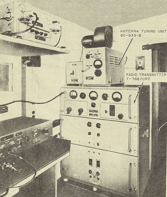
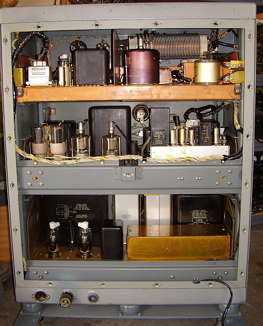
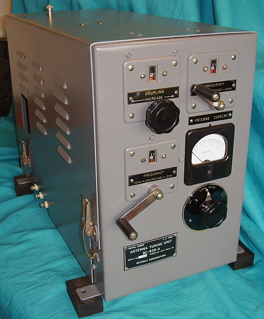
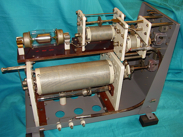
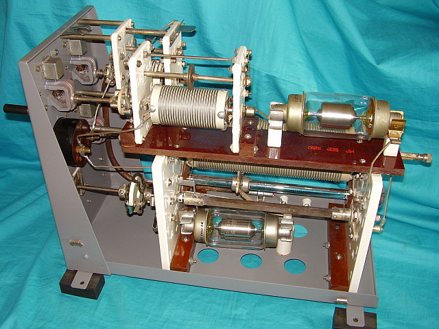
Reassembly - Mechanical alignment has to be carefully performed when reassembling the BC-939. The couplers on the two upper roller inductors don't have flexible hub mounts so the alignment of these two inductors has to be accurate so as not to break the ceramic insulator. The lower switch and inductor should also be close in alignment but since the couplers do have flexible mounts their alignment isn't as critical. I had to use heavy paper shims on the high frequency roller inductor mount to get the alignment correct. The other two roller inductors and the switch aligned using their mounting adjustments.

It's possible to get the antenna selector switch out of synchronization. Watch the rear contacts versus the front contacts and it becomes apparent how the switch should be positioned before the coupler is tightened.

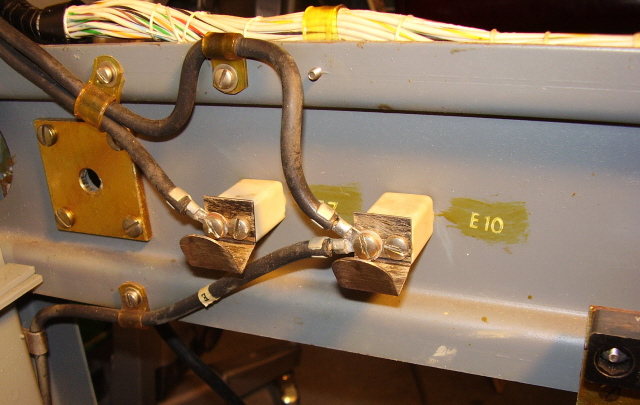
Since the chassis had been bent, the ceramic insulators for the tuner output connections were broken. Although the outer ceramic pieces were in good condition, the internal ceramic that passes through the chassis metal was broken on two of the three insulators. I used epoxy to glue the internal ceramic pieces back together to correct the problem.

The top cover also has a connection piece in the top. It is a ground connection that goes from a top binding post through the cover to an internal contact that presses against a flexible contact plate on the Coupling roller inductor which accomplishes a ground connection at that point. Although the BC-939 is grounded to the transmitter at the side terminals this top connection is used if coaxial cable is used to connect the whip antenna to the tuner. The shield would connect to the top cover binding post and the center conductor would connect to the binding post inside the large circular opening at the rear of the tuner-cover.

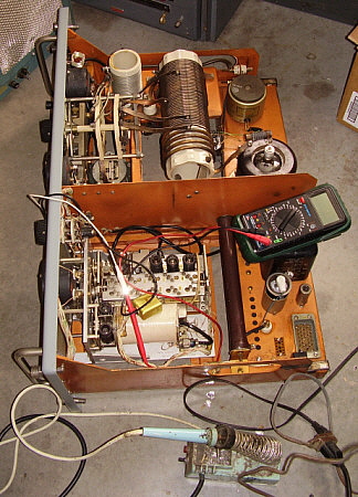
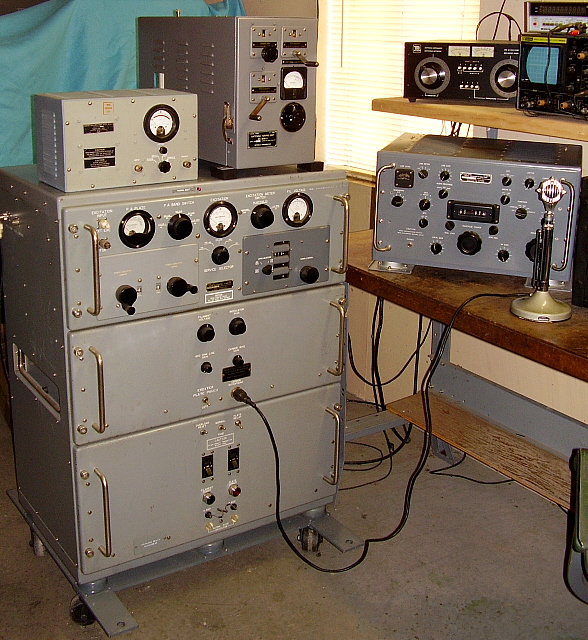
Performance - Not good news for wire antennae - I decided to do my testing at low power - really low power. Rather than using the T-368 for testing, I connected up a Viking Ranger. This limited the RF power to less than 50 watts for testing. Since both the T-368 and Ranger use a Pi-L network type output, the results should be comparable as far as settings and functionality. Once low power applications seem to work then going to high power would show any arcing or other high power problems that might happen.

Futile Empirical Experimentation - I already knew what to expect but I had to go through the experiments anyway - empirical proof and all that sort of stuff. My first attempt was to load my "two half-waves in-phase" antenna with the feed line shorted and then worked against ground. I thought this might work as some sort of random wire antenna load however that antenna had way too much inductance for the BC-939 to provide matching. I tried just one "leg" of the antenna with similar results. Next, I connected a 20 foot long piece of wire. With this "antenna" I could get a very good match on 75M with the BC-939 set for the whip antenna 2mc-10mc range. My next test was to try a 67 foot end-fed wire. I suspected that the "long wire" antennae for the military wasn't really all that long and was probably something easy and quick to erect. I was able to somewhat match the 67 foot wire antenna on the 75M band but the SWR was rather high at about 6:1. It appears that if one really wanted to use the BC-939 with a end-fed wire antenna then a lot of experimenting would be needed to find a wire length that's within the BC-939's tuning range for the intended frequency of operation.

Another Futile Experiment - Obviously, the problem with the BC-939 and random-length end-fed wire antennae is not enough capacitance available in the BC-939. Why not add an external C in series with the wire antenna? A large air variable could be connected in series between the antenna and the tuner and then adjusted to give the best match with, for example, a 125 foot long end-fed wire. So, first I tried 125 feet of wire with a 100pf variable in series between the BC-939 and the antenna. I varied the capacitance from a low of around 15pf up to the 100pf and could not get the tuner to match the 125 feet of wire. I tried both "Long Wire" and "2mc - 10mc" positions with similar results. Next, I went back to the 67 foot wire antenna with the variable-C in series. With this set-up I was able to get a match but the minimum SWR attainable was 6:1.

The next test is to use the air variable C in parallel with the antenna. This test result will be coming soon.

20 foot Vertical -  This antenna is an actual Army antenna with insulated base. I've mounted it on the side of the shop and use a vertical drop ground wire about six feet long that connects to a ground rod.

To Sum it Up -  While there might be a combination of external L or C that might "help" the BC-939 to provide a good match for a "long wire" antenna, it seems to go against the idea of trying to use the equipment "as originally intended." With no external L or C, the best results were with less than 60 feet of wire and while this could be loaded the mismatch was fairly high unless the wire was around 20 feet in length. Perhaps with endless patience a "magic length" long wire could be discovered for a certain, specific frequency but it appears that "random length" long wires cannot be matched.

In the military, a long wire would only be used if communications distance wasn't possible with the vertical whips. This meant that rarely, if at all, would the long wire antenna be used and then if the SWR was 5 or 6 to 1, it didn't matter since it would only be for a short time period. In the Army, if the transmitter could be loaded into the antenna, then the SWR was acceptable. After all, communications was of the upmost importance. Whether the final amplifier tube survived was secondary since spares were always available.

Our experiments seemed to conclude that the BC-939 was primarily designed to match a 15 to 20 foot long vertical whip and it does this function rather well.

The Manual versus Reality - Why the manual TM11-5820-256-10 states that the BC-939 can be used with a dipole antenna is a mystery. I've talked to old ex-army radio ops that actually used T-368s and this is what they say. "The BC-939 was only used to match the whip antenna to the T-368. The other antenna available was a reel-out doublet. With that antenna, we'd calculate the antenna length needed, reel out that much metal tape and then connect the coax directly to the T-368, bypassing the BC-939. At fixed locations we had a specific fixed-frequency that was always used and the antenna was cut for that frequency. The coaxial feed went directly to the T-368." 


ME-165-G SWR Bridge/Dummy Load/Watt Meter

The ME-165-G is a military SWR Bridge with the capability of operating as a Dummy Load with Watt Meter. The Dummy Load is comprised of several wire wound resistors that total 50 ohms and has a dissipation of 200 watts continuous. Although the front panel tag indicates that power levels in excess of 250 watts must be limited to intermittent operation, the dummy load can dissipate up to 600 watts but only for short on/off periods. The meter scale is 600 watts FS.

The SWR Bridge works like any of the older style bridges. With RF power going into the bridge, select ADJUST. Then use the ADJUST knob to set the meter to read full scale. Then switch to SWR and the meter will indicate the SWR. The switch also has a position for OPERATE that allows bypassing the bridge entirely. The POWER position switches in the dummy load and the meter will indicate the RF watts input to the dummy load. The input and output connectors are Type-N coaxial receptacles.

The ME-165-G was usually mounted to the hut wall adjacent to the T-368. The ME-165-G was included in the equipment installed in the AN/GRC-26.

Since there is an OPERATE position which bypasses the bridge, leaving the ME-165-G connected between the transmitter and antenna results in no losses in the OPERATE position.

The ME-165-G shown in the photo to the right was built by Radalab, Inc.          .

 
UPDATE - August 3, 2017 - I had been noticing for about the past six months (or more) the RF power output on the T-368 was slowly decreasing. I'd increase the PLATE LOADING and, for a while, RF power would be back up to around 375 watts. For the past few months, I couldn't get much more than 300 watts RF output and if the PLATE LOADING was increased enough, the RF output would decrease instead of increase. This is "classic case" of a PA tube getting weaker and weaker. I had been given a 4-400A to try but it was pretty dark inside. The more time on a PA tube and the harder it is "worked" the more darkening happens on the inside of the glass envelope. I was sure this tube, if it did improve the RF output, wouldn't do so for very long. I was up at Ham & Hi Fi in Sparks, Nevada on August 2nd and while looking around I remembered that they had some "tested" 4-400A tubes up on eBay.  >>> >>>  The testing was done by my old friend, KB6SCO, and I was familiar with John's methods and his set-up. He used various power supplies running +2KV on the plate and +500vdc on the screen then starting at -100vdc bias, reduced the bias by increments of five volts and measured and logged the plate current at each point. The test data was attached to the tube. I could see that John had gotten about 480 watts on his test at a bias level of -50vdc (Ip x Ep.) I figured this was a pretty good tube. So I purchased the 4-400A and installed it into the T-368 the next morning. Not that there weren't problems, however. It seemed that a "heavy-wristed" installer had broken off the screw that held the plate cap heat dissipater to the tube plate cap. I had to drill out the broken screw - luckily, it was a brass screw. Once the screw was drilled out the dissipater cap could be removed. I had to chase the threads and install a new brass 6-32 screw. That allowed everything to be reinstalled with the new tube in place. Power up and the RF output was 400 watts at 240mA of plate current. Very nice. On the air tests on the Sunday Vintage Military Radio Net garnered many positive reports on the improvement. Well,...probably most of the compliments were due to a change in microphones - from a DN-50 head with Kobetone element to a D-104 head with original Astatic element - but still, the 4-400A helped.
 
Conclusion - The T-368 is one of the most desirable and popular military transmitters for the vintage military radio enthusiast to own and operate provided he has the necessary space for a very large and heavy transmitter. It uses a Collins' designed PTO-Exciter to drive a powerful 4-400 PA tube to maximum legal limits on DSB-AM. The transmitter's construction is probably the most robust that any ham would ever encounter. The T-368 must have cost the military a small fortune for each transmitter. With a history that starts in the very early fifties and goes well into the 1970s, the T-368 did duty in both Korea and Viet Nam, not to mention duty at all of the other military posts all over the world. Many T-368s were "trailered" around in mobile comm-huts running crypto-RTTY. A rugged life for a transmitter, even an "over-built" example like the "T-3." Today, many surviving T-3s are coasting along living the good life. More and more T-3s are being rebuilt and reconditioned for amateur service. Vintage military radio collector-enthusiasts located all around the country know and respect the T-368 as one of the best military transmitters for actual use "on the air" running AM on various types of vintage amateur radio nets. References:

1. Signal Corps manuals TM11-809-10 for the T-368 and BC-939. TM11-5820-256-10 for info on the GRC-26D

2. Thanks to W6AQU, W6MIT, K6RAR and many others for their insight and experiences with T-368 transmitters.

Henry Rogers WA7YBS      December 2016 © Henry Rogers, Western Historic Radio Museum, Radio Boulevard, added 4-400A update Aug 2017,


Return to Home Index


Radio Boulevard
Western Historic Radio Museum

 Vintage Radio Communication Equipment Rebuilding & Restoration Articles,

 Vintage Radio History and WHRM Radio Photo Galleries

1909 - 1969

- 60 years of Radio Technology -


This website created and maintained by: Henry Rogers - Radio Boulevard, Western Historic Radio Museum © 1997/2023