Hammarlund's
SP-600 Super Pro
- In 1948, Hammarlund published an advertisement (see photo
below-left) for the Series 600 Super Pro, the SPC-600-X, receiver that
apparently had all of the features the Signal Corps wanted
and most of the features found on the later SP-600 receiver. The
advertising artwork shows the 1948 concept of the SP-600.
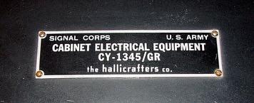
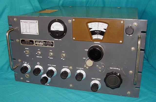
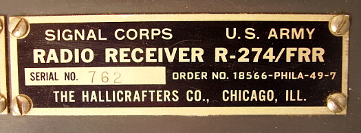
The first actual Signal Corps contract appears to be Contract Order
Number 18566-PHILA-49-7, dating from 1949 and assigned to "The HALLICRAFTERS
Co." (see tag photo lower-right.)
 |
Generally, it's believed that Hammarlund's SP-600 was introduced in 1950
but that may have been an "available to the public"
announcement. Hammarlund was often slow to release official
announcements. As an example, fifteen years earlier, Hammarlund
had produced the SPA receiver, a receiver identical to the SP-10
Super Pro, on a
Signal Corps contract in June 1935. However, they didn't
officially announce the "new" Super Pro SP-10 receiver to the
public until nine months later, in March 1936.
It's probable that Hammarlund was supplying some SP-600-type
receivers to the Signal Corps for testing and evaluation (and
getting feedback for what was needed) long before the
official announcement in 1950. However, there are no official contracts
for SP-600 receivers prior to 1950 and no contract build dates earlier
than September, 1951.
Since Hammarlund was also closely working with the Signal Corps
on better stability in their receivers, just how much of the
SP-600 design was influenced by the Signal Corps is unknown
(other than the obvious.)
|
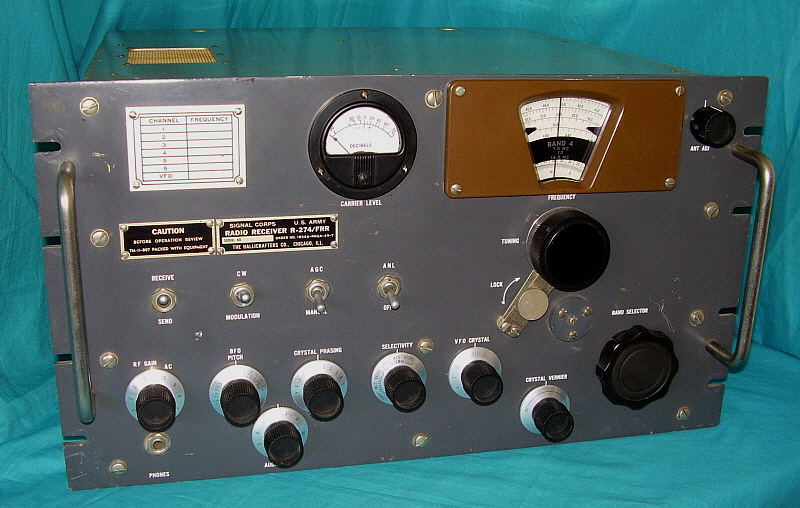
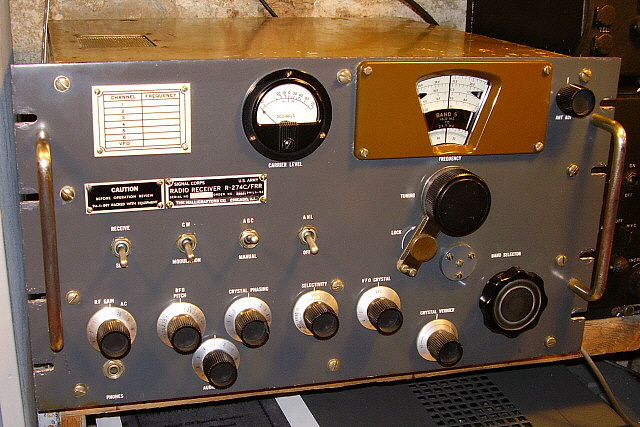
The first official contract for the Hammarlund R-274A is Order
No. 1689-PHILA-51-01 from September, 1951. This receiver was
also designated as the SP-600 JX-1 by Hammarlund. There was an earlier contract for the Signal Corps but it was
for a Hammarlund R-483/FRR (SP-600 JX-5) on contract 21478-PHILA-50 but
the build date was November, 1951.
Other Signal Corps contracts are
Order No. 3376-PHILA-52, originally dating from 1952 but this contract
was built-on for both R-274A and R-274C receivers and SP-600 versions
run up to the JX-26 built in 1953. The R-274B receivers were built for
the U.S. Navy and are on Contract NObsr52039 from 1952 (SP-600 JX-6) and
NObsr71369 (SP-600 JX-35) from 1956. There are seven contracts for Hammarlund R-274A, B and C receivers spanning from 1951 up to 1956.
There appear to
be two contracts for Hallicrafters R274 and R-274D receivers spanning 1949 up to 1952.
On any of these contracts ordering and building could take place over
several orders using the same contract number and fulfilling the order
might take more than one production run and could take many months to
finish (maybe even years.)
Suffixes - When the Signal Corps
and the USN began ordering the Hammarlund SP-600 version of the receiver, the R-274 designation
had already been assigned to Hallicrafters' production. So, rather than assign an
entirely different number to the Hammarlund SP-600, these receivers were given
suffix letters of A (Signal Corps,) B (USN) and C (Signal Corps.) Even though the non-suffix designation had
been assigned to Hallicrafters, their next new contract receivers would be
designated R-274D/FRR. The next known Hallicrafters' contract for the R-274D
was Order No. 3464-PHILA-52
from 1952.
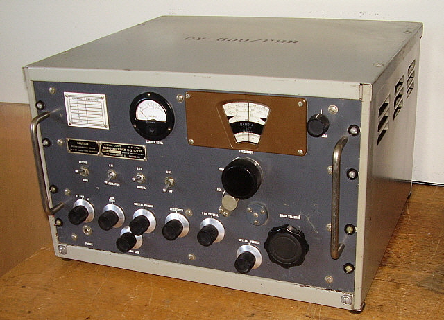
The Hallicrafters R-274 "D" Version
- Probably the biggest change in the new Hallicrafters R-274D was how the remote
standby worked. The original R-274 remote standby worked in parallel
with the front panel Send-Receive switch requiring a NC contact on the
remote standby line for receive and a NO for standby. The NO on the
remote line (with the panel Send-Receive switch in Send) would
disconnect the screen voltage to the two RF amplifiers and the first
conversion mixer stage. To disconnect the antenna from the receiver in
the Send mode would have to be accomplished with an external T-R relay.
The R-274D changed the remote standby to an antenna input protection
circuit. Remote standby required that 12 volts DC be connected to the
rear terminal strip to operate an antenna relay that was inside the
receiver. The relay shorts the antenna input to ground when in the Send
position (12vdc applied to remote terminals.) Also, the receiver antenna
coil selected becomes an open circuit to protect it from any RF radiation
energy. A neon bulb was also added to protect the receiver antenna input
circuit
from static discharges. An external T/R relay would still be required.
Appearance-wise, some R-274D receivers will have gray-color dial
escutcheons. >>> |
>>> Later
Production - With examples of both receivers available to the Signal Corps from
1950 up to about 1952 it seemed that the Signal Corps favored the Hammarlund SP-600
over the Hallicrafters R-274. Over the next decade literally tens of thousands of SP-600s were
produced for the military but the Hallicrafters' version was produced in
just a couple of contracts from 1949 into the early 1950s.
Judging by the scant quantity of Hallicrafters R-274 receivers
encountered today, the contract quantity was probably fairly low, maybe
1000 receivers per contract. Hallicrafters may have expected more
contracts from Signal Corps but it seems that only a couple of contracts account for all
R-274/FRR and R-274D/FRR receivers. How popular the R-274 receivers were
with the Signal Corps is difficult to establish
but few (if any) are ever seen in vintage military photographs. However,
I was sent a photo showing R-274 receivers being used for surveillance
by the military. Trouble is,...it's the Belgium Military. But, that
shows that the sale of R-274 receivers wasn't limited to the U.S. Army
Signal Corps. Thanks to Belgium SWL Jacques Van Cranenbroeck for the
photo which is shown below in the "R-274 Performance Today" section of
this article.
Since
the contracts only accounted for a relatively small quantity of
receivers and Hallicrafters had obviously done substantial production
line tooling and had set up suppliers for the required parts, it was not
going to be profitable if only a couple of contracts resulted from these
expenditures. Like
other manufacturers that provided the military with radio equipment,
e.g. Hammarlund and their SP-600, Hallicrafters decided to offer the
R-274D to the commercial and amateur market. To avoid any confusion as to
the intended customers, these Hallicrafters receivers were given a new designation of
SX-73.
|
 |
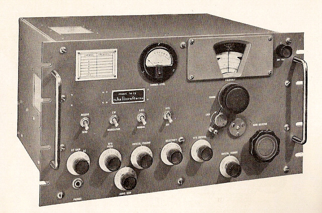
The SX-73 - At
$975, the sales of SX-73 receivers must have been incredibly slow. Note the B&W artwork in the
header photo and see that the data plate was changed to "SX-73"
and the "CAUTION" tag deleted. It's entirely possible that the SX-73
receivers that were sold were surplus builds of the R-274D that
Hallicrafters had produced in anticipation of further orders from the
Army that didn't materialize. A SX-73 cabinet is mentioned in the Hallicrafters'
ads but usually the artwork shows the SX-73 as a rack mount receiver.
There was at least one advertisement artwork that showed an SX-73 that
was repackaged to look like a civilian Hallicrafters'
product with large dial and meter bezels along with stylized grab
handles and cabinet. It seems unlikely that Hallicrafters would have
dumped even more money into a design revamp that would have probably
ended up with the SX-73 being even more expensive.
Today, the SX-73 version is rarely encountered, however the
military versions R-274 and R-274D do show up from time to time. These
receivers have a dedicated following of enthusiasts who actively use
their receivers. From serious SWLs to hams using the R-274 for
communications in Vintage Ham Stations, both are users who want a
receiver that features impressive sensitivity and great audio
reproduction along with a Spartan-like military appearance.
R-274 and SP-600
versus Collins
for Signal Corps RTTY Use - Radio Teletype (RTTY) was the initial
reason for the Signal Corps' interest in a stable, crystal-controlled
receiver that was capable of dependable data reception. By 1950, Collins
Radio Company had started to supply the Signal Corps with 51J receivers
that had a frequency readout that was accurate "to the kilocycle" and
frequency stability that was essentially drift-free. The next year, the Collins R-390
was released and it was also accurate and drift-free (and expensive.)
Ultimately, these Collins receivers were what the Signal Corps used for RTTY, installing both the 51J (R-388) and the R-390/R-390A in portable
communication huts specifically for RTTY communications. The fate of the
Hallicrafters R-274 was no more contracts after 1952. The fate of the
Hammarlund SP-600 was greatly reduced numbers produced after the
mid-to-late-1950s. Although Hallicrafters tried to market the R-274D as the
SX-73, very few were actually sold. It was the end of the design for Hallicrafters and they really never produced a similar receiver
afterwards. Hallicrafters must have lost a substantial amount of money with the
R-274/SX73 production. However, most enthusiasts maintain that the R-274 was Hallicrafters'
best-effort in receiver performance and design (acknowledging the Signal Corps
influence, of course.) NOTE: Throughout the
remainder of this article, the Hallicrafters' receiver designation R-274
is used almost exclusively to avoid repetitious listing of both designations.
Just remember that the earliest version was the R-274 receiver and the
later version was designated as the R-274D receiver. Also, Hammarlund
R-274A, B or C receivers are referred to as "SP-600" for the same
reason. |