Radio Boulevard
Western Historic Radio Museum
 

Rebuilding the BC-348 Family of Receivers
(includes Grid-Cap, Single End & BC-224)

Information in Part 1 - BC-348 History, Missing Parts, Dynamotor Service and Retrofit for Q,N & J Versions

Information in Part 2 - Dynamotor Retrofit for BC-348 Grid Cap Versions, Retrofit for BC-224

Information in Part 3 - Expected Performance, Better AC Power Supplies, Painting Wrinkle Finish

 
by: Henry Rogers WA7YBS/WHRM

PART 2


Part Two -  BC-348 - The "Grid Cap" Tubes Versions

Let's start out by recognizing that the Grid-Cap Tubes (GCT) version of the BC-348 is a completely different receiver if compared to the later Single-Ended Tubes (SET) version. The SET version was not given a new designation because the SET version was a "cost reduced" design that had to be interchangeable for the end user. But we are looking at the circuit in order to restore the GTC version back to original dynamotor operation and the first thing that will be encountered is that the earlier receiver circuit is 90% different from the later versions. Even the component designations are different for the few identical components encountered. Also, within all of the GCT versions there are many slight variations in components used and construction, so the first thing you'll need is the proper documentation for your particular GCT version and, if a "parts set" is needed for the restoration, it should be a similar vintage GCT version receiver.

Accessing Your Restoration Candidate

Despite their differences, much of what is presented in Part One is applicable to the earlier GCT versions of the BC-348. Since the receivers were considered interchangeable for the end-user, the exterior of the receiver is almost identical to the later versions. This means that a lot of the chassis, cabinet and some panel parts are interchangeable. Also, the general retrofit techniques presented in Part One are applicable to the earlier receivers. But, a look at the circuit or schematic will show you that we are going to be working on a very different receiver. Here are some of the main differences:

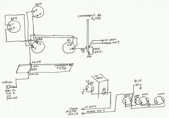
1. Early versions (GCT version) use entirely different tubes. The RF amps and one IF amp are 6K7s, a 41 is used for the audio output, the LO is a 6J5 and the Mixer is a 6L7. These tubes functions were replaced with 6SK7, 6K6 and 6SA7 tubes in the later receivers.

2. A 991 Neon bulb is used a a voltage regulator for the LO on GCT receivers. Not used in SET receivers.

3. A 6F7 (large seven pin glass tube) is used as the 2IF and BFO functions. This tube will have a separate metal shield installed. This tube's functions were replaced by the 6SR7 and the 6SJ7 in the SET versions.

4. A 6B8 is used for the 3IF and Det/AVC functions. This metal octal with a grid cap tube was replaced by the 6SR7 and 6SJ7 tubes in the SET version.

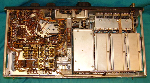
5. The BFO and the Crystal Filter are fully shielded in square cans mounted on the top of the chassis.

6. A tracking RF gain control is coupled to the tuning condenser. Not used on SET versions.

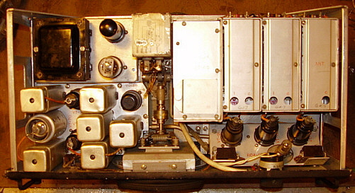
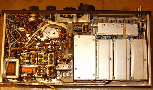
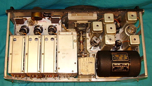
7. The receiver construction uses component mounting that is "old-style RCA" using four component mounting boards with wires routed through a harness down to the tubes. This was simplified for the SET versions to mount most of the components on or near the tube sockets with only two component boards utilized. The use of so many component boards means much of the wiring is in harnesses that makes "wire tracing" very difficult.

8. Capacitor mounting under the dynamotor uses several individual metal body, oil filled, dual capacitors mounted together and connected to the circuit through wires in the harness. The SET version simplifies the component placement and use.

9. Placement of the audio output tube is significantly different with early versions locating the type 41 on the main chassis near the audio output transformer. The SET version locates the 6K6 on the small chassis on the right front of the receiver (with the two RF amplifier tubes - where the mixer tube is on early versions.) NOTE: Some GCT versions have a type 6K6 audio output tube.

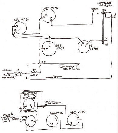
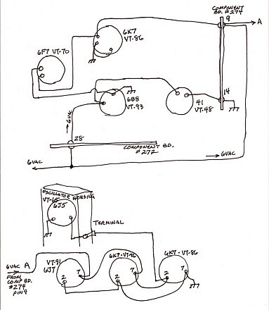
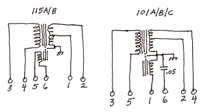
There are several more changes such as layout, component designations and manufacturers used, wiring harness, etc. Since different tubes are utilized, the original series-parallel wiring is slightly different than the single-ended tubes version and the conversion to AC was slightly different. Dial lamp conversion is slightly different because of the +28vdc source changed in later receivers. You will have to make use of the correct wiring diagram for the early receivers. This is not a schematic but a pictorial of how the wires are connected to the various components, component boards and the harnesses.
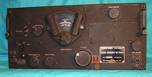
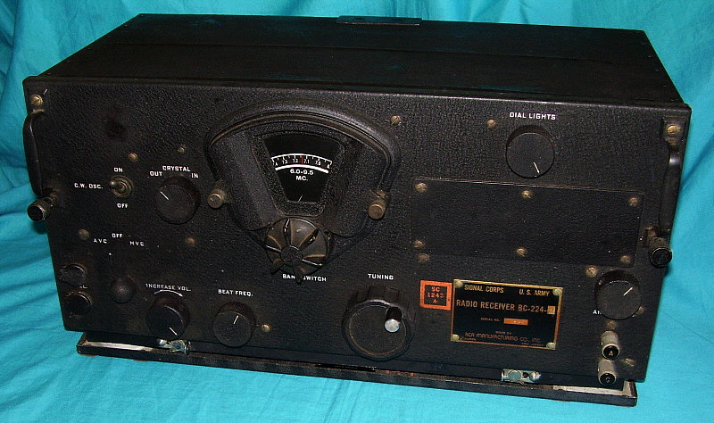
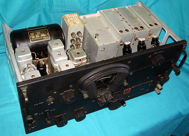
BC-348-C Assessment

 The victim,...I mean the receiver (shown above) to be retrofitted with the DM-28 dynamotor belongs to KØDWC who intends to run this BC-348-C in the ARC-8 configuration (with a dynamotor operated ART-13 transmitter.) The BC-348-C version was built by RCA in 1941. It was common to convert the "B" or "C" variations to cover 200kc to 500kc and then re-designate those receivers as "R."  However, this particular "C" has not had the LF conversion making it somewhat rare.

Unfortunately, like much of the rare military gear that is found today, this early BC-348-C was at one time owned (and hacked up) by an avid reader of CQ magazine publications. CQ advocated the wholesale destruction of much of the military surplus gear under the guise of "modifications for ham radio operation" - in other words, mods that were poorly engineered and, in most cases, unnecessary. "Modification for modification's sake" was the CQ motto and many hams bought into the idea that they could "out engineer" the Professional Radio Engineering Teams that designed military radio gear to perform reliably under the worst conditions imaginable. Also, that they (the hams) could perform the mechanical and technical work better than the professional radio assemblers and technicians that were employed by the major radio manufacturing companies. Today we see these "hamster" results in the sloppy workmanship of hacked up modified gear we have to try to restore back to original operation and performance. A properly designed AC power supply conversion that was well-thought-out and well filtered was all that was necessary as a modification and this would not be a serious problem to convert back to dynamotor operation (or use "as-is.") However, this BC-348-C example we are restoring has had several other modifications besides the AC power supply and the quality of design and rework are strictly of the "hamster" caliber. Luckily for military radio enthusiasts, most BC-348 receivers encountered are usually not nearly so compromised by modifications as this example was.

photo left:  Note the metal octal tube on the AC power supply. This is a 6F6 audio output modification. Also note the metal octal next to the band switch drive. This is the 6C5 "hacked" in to replace the 41 audio output tube and convert that stage to a 1st audio amplifier stage to drive the 6F6. Note the cable routed to where the DIAL LIGHTS control was. This is now a separate AF Gain control and ON/OFF switch.

photo right: Lots of extra cables and components added here to further confuse anyone who attempts to restore this example back to original. The fuse mount and the SO-143 were missing. Replacements are installed but not wired - yet.

Preliminary Inspection - The photos above show the BC-348-C chassis in "as found" condition. A poorly designed and inadequately filtered AC power supply is obvious when looking at the photo above right. Also, note that an audio output stage has been added using a 6F6 tube. Additionally, the original type 41 audio output tube was removed, the large six pin socket removed and an octal socket installed so the stage could be changed to a 6C5 First AF Amplifier to drive the 6F6. Due to the poorly filtered AC supply and the additional amplification, the hum level in this BC-348 was exceptionally loud. Totally unnecessary modifications resulting in poor performance! The original audio output circuit is sufficient to drive a matched load to high volume.

Unfortunately, the modifier decided to grind off the bosses and drill-out the threads that are normally used to mount the dynamotor (or the typical AC power supply.) This means that helicoils and spacers will have to be installed to assure that the DM-28 mounts to the chassis correctly. Also, the DIAL LIGHTS control has been replaced with an "on-off" switch/AF Gain combo (another circuit modification.) Luckily, KØDWC supplied a SO-143 connector and an original type audio output transformer (note that neither is wired into the circuit.)

Note in the photo of the underneath that a filter choke was mounted to the side panel. This required removal of the original Candohm resistor pack to allow clearance. The shielded cables are additions for the 6F6 mod and the twisted pair of white wires go to the mod'd AF/Gain and "on-off" switch.

All of the front panel modification holes had already been repaired by KØDWC so they are not easily seen. The other "hamster" mods included the addition of an SO-239 connector for the antenna and ground connections and an additional switch in the upper left panel area (repair of the holes might be visible in the front panel photos.)

All things considered, this BC-348 would probably have been a "parts set" had it not been the rare "C" version without the LF conversion. Although the receiver has been severely altered, it can be restored back to its original configuration using a DM-28 for it power source.

Commonly Missing Parts and Required Documentation

Fortunately, many of the hard to find parts are the same in both versions of the BC-348.

DM-28 Dynamotor - Same in both versions, the DM-28. Covered in Part One.

SO-143 - Power Input Connector is the same in both versions. Covered in Part One.

115A/B Audio Output Transformer/Choke - This unit is somewhat different in the GCT versions and is designated 101A/B/C or 123A/B/C. One side of the choke is connected to chassis internally, .05uf capacitor connects to pin 6 (C-101 - BFO TC) and the audio output transformer connects to different pins. You can substitute 115A/B for the earlier 101A/B/C or 123A/B/C but be aware that it has to be connected differently. More details below in "Substituting 115A/B for missing 101A/B/C."

FT-154 & PL-103 - The same shock mount and connector for both versions. Covered in Part One.

Filter Capacitor 70 - This dual filter capacitor is only in the Q, N and J versions. The GCT version uses several oil filled, dual capacitors connected via the harness to the circuit.

Resistors - Most GCT versions have R-501A/B removed to operate the tube heaters on 6.3vac. R-501A/B consists of a 3.0 ohm 1.5 watt WW resistor and a 190 ohm 1.5 watt WW, both in a package that looks somewhat like a Candohm-type resistor. The series resistor (3.0 ohm) limits the surge current on cold heaters and the parallel resistor (190 ohm) will slightly raise the heater voltage on the audio output tube heater. Some versions have different component designations but the values and function are the same. The load resistor and potentiometer for the dial lamps have the same values as the later versions but the designations are R-503 for the 60 ohm load and R-500 for the 200 ohm potentiometer (but designations do vary with the particular version within the GCT classification.)

Nomenclature Note - Since the GCT versions are different receivers as far as the circuit and tube types used, different designations are used for all of the resistors and capacitors that perform similar functions in the Q, N and J versions. Also note that since the GCT version was built longer and by more contractors than the SET versions, the component designations are somewhat different within the various GCT types. Check your particular GCT version against all of the earlier documentation to decide what is correct for your BC-348. As with our reference to the various components in Part One, I add "R" or "C" to resistors or capacitors so the reader can easily identify the type of component referenced. In the manual or schematic these components are only identified by the number.

Schematic - The GCT version schematic is available on the BAMA site. Also available is the complete manual for the early BC-348 series that has wiring diagrams, parts lists and a lot of other useful information. It's a large file at around 9meg but the wiring diagrams are required, so download it.

Use the Wiring Diagrams - Wiring diagrams are not schematics. Wiring diagrams are pictorial drawings that show the exact routing of all of the wires and their connections to all of the receiver components. The GCT version of the BC-348 is very difficult to "trace out" the wires when trying to find out how a particular receiver has been modified. This is because most of the wiring is routed through harnesses with connections to the different component boards. The easiest way to trace the wiring is to have copies of the wiring diagrams that are in the military manuals. These diagrams show where the original wiring was connected and how it was routed through the harnesses. Using the wiring diagrams will give wire colors but these changed depending on the contractor so you can't go just by the indicated color. You will still have to confirm the correct wires and connections using an ohm meter.

Changing the Tube Heater Wiring back to Series-Parallel

Original Series-Parallel Connections for +28vdc Operation - Since the GCT version makes extensive use of harness routing, the tube heater wiring, at first, seems confusing. This is mainly due to R-501A/B. This WW resistor package is mounted at the back of the chassis (under the dynamotor) so wires have to be routed via the harnesses to make those connections. Two different component boards are utilized in the routing.

The simplified drawing below shows the correct original wiring for a Series-Parallel connection of the tube heaters to allow operation on +24vdc to +28vdc. If your version uses the 6K6 Audio Output tube then the heater connections are to pins 2 and 7 on that socket.

Modified Parallel Connections for 6.3vac Operation - The simplified drawing below shows the Parallel 6.3vac AC hook-up for the tube heaters that I found in this BC-348-C. Note that R 501A/B is removed so that the 6.3vac heater voltage connects direct in parallel to all of the tubes. On this example, the three wires that originally connected to R-501A/B were all soldered together and taped. It may not be how all examples are modified for AC filament operation, since this receiver had so many other modifications. Generally though, there aren't too many different ways to accomplish the parallel heater connection. If your version uses the 6K6 Audio Output tube then the heater connections are to pins 2 and 7 on that socket.
 

Miscellaneous Information

Connecting the Dial Lights in Series for GCT Versions - The series wiring for the dial lamps starts from the +28vdc connection on pin 1-Front Switch of the AVC-MVC switch then proceeds through the two lamps in series then exits from the dial housing to the 200 ohm pot and the 60 ohm load. The usual AC power mod is to move the voltage source from the AVC-MVC switch to one of the tube sockets for a 6.3vac voltage source. The lamps are then connected in parallel. The exiting wire on the right side is usually just connected to the chassis but sometimes is routed to a switch or to the 200 ohm pot without the use of the 60 ohm series load. To return to series wiring, remove the added parallel wire between the two lamp sockets. Then move the original wire that was moved to parallel the incoming voltage connection on the left side socket and move it to the other lamp socket connection. That should be all that is necessary under the dial cover. What is needed from the right side wire is a connection to the 200 ohm DIAL LIGHTS potentiometer and 60 ohm load resistor and then to chassis. Also, on the left side wire, the source of the voltage has to be removed from the tube socket and reconnected to the AVC-MVC switch. This completes the circuit. Be sure that you use #47 lamps in the dial.

Micamold Capacitor and IRC Resistor Replacement - On the GCT versions only, Micamold capacitors are used for many bypass and coupling functions. Micamolds are not mica capacitors but are rather paper-wax capacitors inside a molded case. They suffer from the same problems that Sprague "Black Beauties" suffer from, that is, excessive leakage current (only Micamolds are much worse than "Black Beauties" when it comes to reliability.) Inspect your BC-348 carefully and replace any Micamolds that show obvious swelling in the center. This is always an indication of heat build-up due to leakage current. If you plan on using your BC-348 as a station receiver, it's probably a good idea to replace all of the Micamold capacitors in the receiver as they will usually result in frequent rework issues if left in the circuit.

The resistors used in most of the GTC versions are International Resistance Corp., IRC, manufacture. For some reason, the IRC resistors made during WWII (and for sometime afterwards) exhibit chronic drift problems. It is not predictable as to whether high values, e.g., over 100K, will drift higher or whether the lower values will suffer value drift. It's best to check all of the resistors for drift and replace any that are more than 20% out of tolerance. Also, if the resistor is associated with a Micamold capacitor (such as a screen load R in the IF amplifiers,) if that Micamold had sufficient leakage current, it would overheat the load resistor and could change its value significantly.

VT Tube Designations for the Grid-Capped Tubes Versions        VT-48 = 41      VT-93 = 6B8       VT-70 =  6F7          VT-65 = 6J5         VT-91 = 6J7         VT-86 = 6K7

Substituting 115A/B for Missing 101A/B/C or 123A/B/C - This BC-348-C was missing the original 101A/B/C audio output unit which is a transformer/choke/capacitor combination. This unit is identified as 123A/B/C in the later GCT versions. I had only a 115A/B available for installation. Here's the pin connections that have to be changed if you find yourself in a similar predicament. Be aware that 101A/B/C & 123A/B/C also had a .05uf capacitor internally connected to pin 6.

101A/B/C       1        2        3        4        5        6  - (6 connected to .05uf capacitor to chassis, pin 1 is the choke - aka 123A/B/C)
115A/B           5        1        3        2        4        6  - (6 is connected to one end of the choke and pin 5 is the other end of the choke)

Using a 115A/B to replace a 101A/B/C requires pin 6 of the 115A/B to be tied to chassis but the wire that comes from the BFO switch must be connected to a .05uf capacitor to chassis. In an early versus late comparison, there are two resistors externally connected to 115A/B in the later versions of the receiver. These need to be removed if it is necessary to sub the 115A/B for a missing 101A/B/C. A few of the latest versions of the GCT version used the 115A/B transformer and are wired accordingly. Check your particular GCT version using the correct documentation. There are many slight variations from contract to contract.

Rebuilding the Dynamotor Connections from the Harness - Most of the time the harness spade lugs had to be removed for solder connections to the AC power supply. See this subject in Part One as it is an identical procedure for the GCT versions.

Rebuilding the DM-28 Dynamotor - See this subject covered in Part One. The procedure is the same.

Alignment - This is basically the same although the locations of the IF and RF tracking adjustments are somewhat different. Different type trimmer capacitors are used in the earlier versions but they are a better quality component than the types used in the SET versions. The same basic procedure is used for either type receiver. 915kc IF frequency. Be sure to do the IF alignment with the Crystal Filter ON (in the circuit.) There is an adjustment for the Crystal Filter accessed from the top of the can. Adjust this for highest gain first and then trim for best Crystal Filter action. This will assure you have a working Crystal Filter that will be an asset to operation of your BC-348.

Power Up - Same as covered in Part One.

photo left: Top of the chassis with the BC-348-C finished and the DM-28 installed. When compared to the before photo, note that now a type 41 tube is installed for the audio output. This required re-installation of a fiber-type large six pin tube socket, as original.

photo right
: Underneath the BC-348C. Much cleaner wiring now that it is back to original. Note that 501A/B is two modern WW resistors that are mounted on a vintage fiber component board.


Part Three - BC-224, the +12 to +14 VDC Receiver

The BC-224 is quite similar to the GCT version of the BC-348 except that the tube heaters are wired differently and the dynamotor (along with the tube heaters) operate on +12 to +14 vdc. The initial BC-224-A is a very different receiver - after all, it came out in 1935. The later versions were built to be very similar to the BC-348 except for power requirements. Both appearance and performance are just about the same as the BC-348. Since the BC-224 only was built up to 1942, it's not very common and therefore it's lucky that nearly all of the parts are exactly the same as the BC-348. The exceptions are the DM-24 dynamotor and the receiver data plate.

I obtained this BC-224-H receiver in a trade that involved some restoration work on a couple of early Crosley battery sets. As usual, the BC-224 receiver had a couple of "hamster mods." The most serious was a non-original toggle switch (used for AC power "on-off") located just above the CW OSC switch. The other mod was the typical inadequately filtered AC power supply installed in the dynamotor bay. Luckily, the BC-224 mods were not very invasive and only the non-original hole was a serious problem. There was also a large exit hole in the back of the cabinet for the AC power cord but since the bottom rail (which has the two slide-clips) had been cut off, I wasn't going to be able to use the cabinet anyway.  >>> >>>  My first thought was to rebuild the AC power supply into a dual section filtered supply that would allow the BC-224 to operate without hum. In talking to fellow military radio enthusiast, KØDWC, his suggestion was to try to locate a DM-24 dynamotor and retrofit the receiver with its correct power unit and run the set "original." Sounded like a good idea!

The next weekend I casually mentioned my DM-24 quest on the Vintage Military Collector's Net and was surprised when W6JRY came back with the statement ", I just looked in my dynamotor junk box and the one on the top of the pile was a DM-24." We agreed on a trade of some matching vintage air condensers and meters for one of Jerry's projects and the trade took place.

Dynamotor Servicing - This is covered in the section above on the DM-24 and DM-28 dynamotors. The photos in that section are of the DM-24 used in this receiver.

Front Panel Hole Problem - A non-original toggle switch was located just above the CW OSC switch. This is a common modification done in the 1950s to allow an AC ON-OFF switch to be mounted on the front panel. With just a little bit of thought, the perpetrator could actually have used the AVC-OFF-MVC switch (as original) instead. But, many of the AC power supplies found in BC-348s or BC-224s were installed by dealer back in the early-1950s. You could buy the DC receiver and for an extra $15, the dealer would add the AC power supply (goodbye dynamotor.) This toggle switch location is very typical of a "dealer installation."

The AC toggle switch wiring used some unused posts on the rear component board so electrical removal was no problem. The AC power supply was also removed. Luckily, the modifications used the original dynamotor harness which was still intact.

To fill the hole, I used five minute epoxy. First clean the surfaces. Then apply a piece of masking tape over the hole on the front of the panel. Turn the receiver on its face - knobs down on the table. Mix up the epoxy and fill the hole from the rear. Let the epoxy set up for several hours (overnight is better.) Then remove the tape and what you should find is a perfectly flat patch to the hole. I used Artist's Acrylic Mars Black to paint the hole patch. You can texture the acrylic using a Q-tip to get it to match. The photo right shows the patch much more prominently than it really appears. This is due to the camera flash.


photo above: The BC-224-H after dynamotor retrofit and cosmetic cleaning. The receiver is mounted on the FT-154 shock mount.

Cabinet Problem - As mentioned above, the modifications to the cabinet destroyed its ability to be used with an FT-154 shock mount since there was no way to secure the receiver without the slide clips. Luckily, I had a couple of spare cabinets and I selected the best one to use. I noticed that the tag inside indicated that the cabinet was for a BC-348-Q but all of the cabinets are very nearly identical and interchangeable. I managed to remove the original paper label from the old cabinet so I had a good BC-224-H label and after removing the BC-348-Q label, the "224" label was mounted instead. A touch-up paint job was necessary since there was some much paint missing. I first touch up where the paint is missing using Artist's Acrylic Mars Black. After the touch ups are dry, I apply a very thin coat of Mars Black (that has been watered down to thin) to even out the color. This coat has to be applied with a fairly wide brush quickly. Don't brush hard or you'll remove the touch-ups. This last coat is just to even out the color so the touch-ups don't show. Documentation Necessary for Retrofit - The BC-224-H manual is available on BAMA edebris. Be sure to down load the combination manual. This will be for both the BC-348 series and the BC-224 series. Inside the manual are the necessary schematics, wiring diagrams, component board layouts and dynamotor rebuilding information. Also, a parts list for both receivers and alignment information. You will absolutely need the wiring diagrams. These are not schematics but are detailed drawings of exactly where the wires are connected and how they are routed in the receiver. Since the BC-224 is a GCT version receiver and it makes use of several component boards tracing wires is difficult because most wires are routed via harnesses. The wiring diagrams give you all of the details necessary to confirm what modifications were done to your BC-224 and how to put it back to original.


photo above: Wiring diagram of BC-224 showing original tube heater connections for DC operation

Converting AC Operation Modification back to Original DC - To run the tube heaters on 6.3vac only required a few modifications. The heaters were in series-parallel for +12 to 14vdc operation. Originally, two parallel sets of four tubes were connected in series. This essentially was a 6vdc load plus a second 6vdc load for 12vdc total heater voltage requirement. The original wiring for +12 to +14vdc is shown in the diagram to the left. The usual modification for 6.3vac operation was very simple to accomplish and luckily it's just as easy to remove and put back to original DC operation. The modification for 6.3vac required grounding the IF-AF tube heaters at the 6B8 tube on pin 2. There was a chassis soldering lug adjacent to the 6B8 so this was an easy addition. The next mod for AC operation was to locate the wire that comes from pin 13 of the Component Board #274 and is connected to pin 1 of the type 41 tube. This wire is then disconnected from pin 1 and reconnected to pin 6 of the type 41 tube. These two changes were all that was required to then operate the tube heaters on 6.3vac. Usually R54 (on Component Board #272) is shorted out with a wire jumper across the resistor.

To reverse the modification only requires that the one jumper to ground from pin 2 of the 6B8 tube be removed. Then the connection on the type 41 tube that comes from pin 13 on Comp Bd #274 be moved back to pin 1 (from pin 6.) With these two changes the tube heaters are now again in series-parallel. Check R54 and make sure it is in the circuit (remove jumper if that's installed or install a .5 ohm WW resistor if R54 was removed.) There were no modifications required to the tube chassis behind the front panel inspection plate since a ground connection was already there for the AC mod and is the same ground needed for DC operation. Again, check to make sure that resistors 54 and 55 are still installed. If not 55 is a 68 ohm 2W CC resistor and 54 is a 0.5 ohm 5W WW resistor.


photo above: The BC-224-H after retrofit of the correct DM-24-H dynamotor

DC Operation of the Dial Lamps - The dial lamps are connected to the AVC-OFF-MVC switch and ultimately connected to pin 2 of the DM-24 which connected +12 to +14vdc to the dial lamps when the receiver was turned on. The dial lamps usually are connected in parallel for 6.3vac operation and need to be put back to a series connection for +12 to +14vdc operation. Usually the socket shells are grounded and the two center connections are tied together for parallel operation. R60 is disconnected. If R60 (DIAL LAMPS pot) is still present then reconnecting for series operation on +12 to +14vdc is simple. The lamp sockets can't be connected to chassis for DC operation so make sure however this was accomplished is removed. Then wire the socket from the left side lamp to the center pin of the right side lamp and the connect the right side lamp's shell to R-60. Make sure that the source voltage to the left side lamp is from the AVC-OFF-MVC switch (and ultimately connected to pin 2 of the DM-24 dynamotor harness.

Test & Alignment - After rechecking all of the retrofit to make sure everything was accomplished, I connected a +14vdc 18A power supply to pins 3 & 4 for +14 and pins 7 & 8 for -14. I used heavy clip leads for the connections since this was just a test. With application of power, the DM-24 came up to speed, the dial lamps illuminated and after about 30 seconds audio came over the LS-3 loudspeaker. With a 25 ft long wire laying on the floor several stations were received which confirmed that the receiver basically worked.

The next step was aligning the IF and RF which is performed exactly like the GCT BC-348, so I won't bother repeating it again. After alignment, the BC-224 functions exactly like a GCT BC-348. The two receivers are basically the same except for the tube heater wiring and the dynamotor, so similar performance should be expected.  

CONTINUE TO PART 3


BC-348 Part 1                           Return to Home Index


Radio Boulevard
Western Historic Radio Museum

 Vintage Radio Communication Equipment Rebuilding & Restoration Articles,

 Vintage Radio History and WHRM Radio Photo Galleries

1909 - 1969

- 60 years of Radio Technology -


This website created and maintained by: Henry Rogers - Radio Boulevard, Western Historic Radio Museum © 1997/2023