|
Before the BC-348 came
about there was an earlier version of this famous Aircraft Receiver. It
was the BC-224 and it was designed by RCA around 1935. It was a 12 volt DC operated
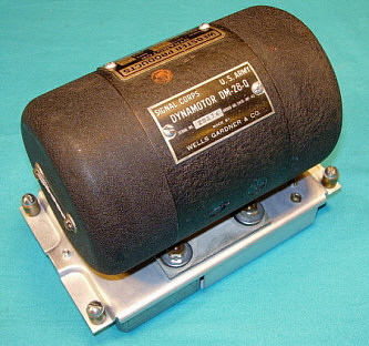
receiver that provided B+ via an onboard dynamotor. The first BC-224
receivers had the tuning dial at the far left of the
front panel giving the receiver a dramatically different appearance.
When the BC-224 was first produced most aircraft systems ran on 12-14vdc.
However, by the late-thirties, many aircraft systems were beginning to
use 24-28vdc which required RCA to develop another receiver to run on 28vdc
which was designated as the BC-348. Simultaneous with the release of the
BC-348, RCA redesigned the BC-224 to have the same external appearance
as the new BC-348. All versions of these early receivers were built by RCA Manufacturing Co.,
Inc., a subsidiary of RCA that built most of their commercial and
military contracts. Both versions, the BC-224 and the BC-348, were built
up to 1942, when contacts for the BC-224 versions stop. All BC-224
receivers were built by RCA Manufacturing Co., Inc. with the exception
of one contact. The BC-348 contacts continued through WWII with the
greatest quantities built during the 1943-44 time period.
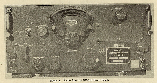
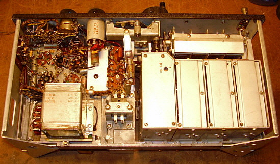
The BC-348 operates on
24-28vdc with the high voltage (~+220vdc) provided by an internal
dynamotor. Over 200,000 BC-348 receivers were built during WWII by many
different contractors building many different versions within that time
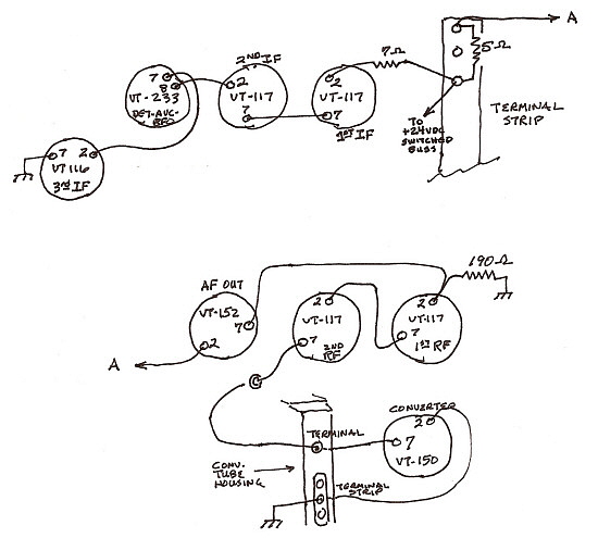
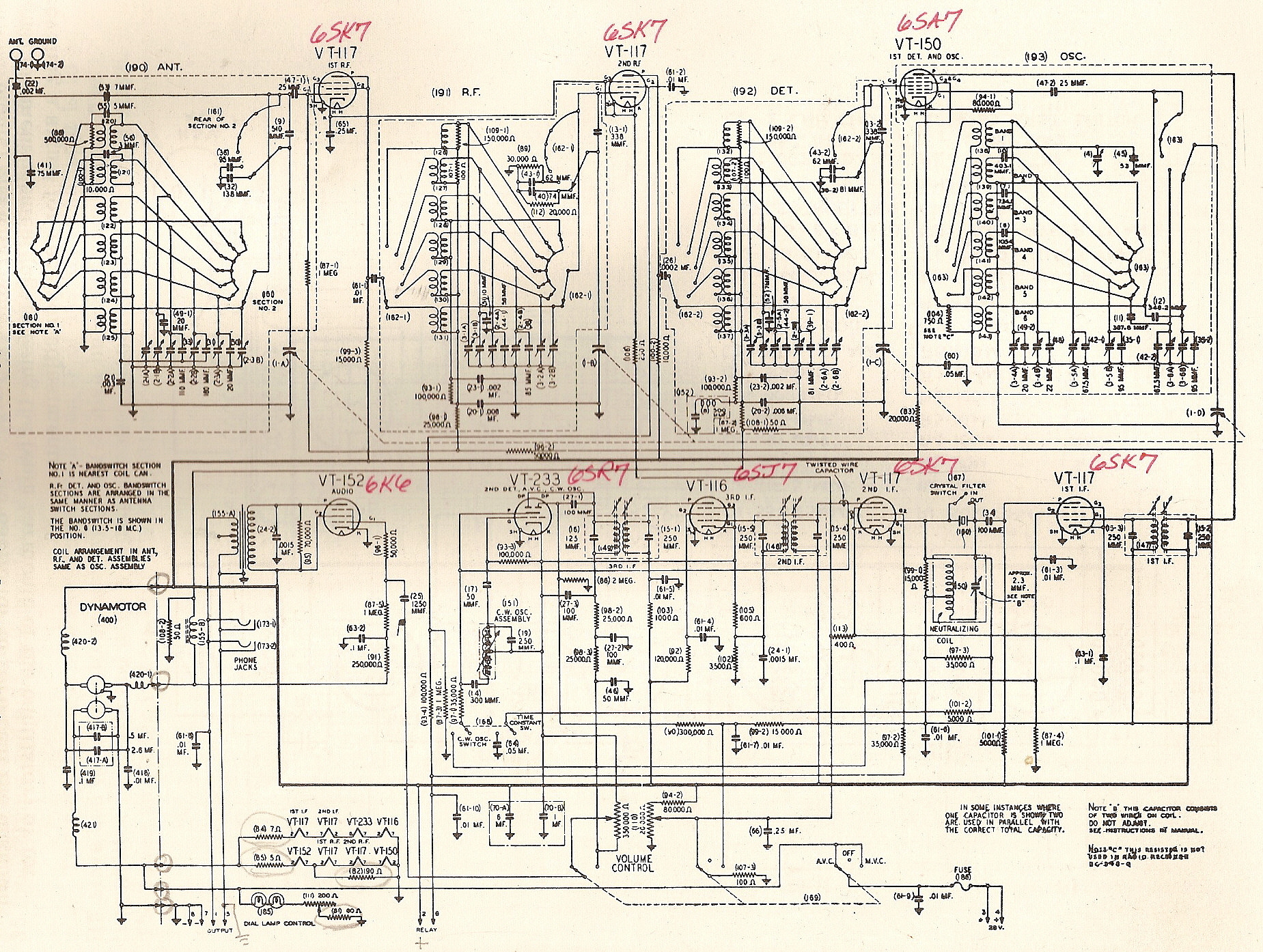
period. The "Early" circuit used eight tubes with the heaters originally wired
in series-parallel for 24vdc operation (two parallel strings of four 6
volt tube heaters in series would operate on 24vdc.) The "early" circuit
provided two RF amplifiers, a Mixer, a Local Oscillator, an IF amplifier
stage, a combination 2nd IF amp and BFO, a combination 3rd IF amp and
Detector/AVC followed by a type 41 audio output stage (this was changed
to a 6K6 in some later versions.) Early versions also will have a 991 neon lamp
acting as a regulator on the local oscillator and will provide
an antenna trim control. A selectable crystal filter was also included
in the circuit. The dual dial lamps were adjustable for brightness and
were wired in series through a potentiometer and fixed resistor.
Frequency coverage was from 200-500kc (not on the B or C version) and
1.5-18mc. The audio output impedance was internally selectable at "low
Z" which was around 300 Z ohms or "high Z" which was around 4000 Z ohms.
Some BC-348s will have a decal on the front panel indicating if the "low
Z" was optioned. During the middle of
WWII, the BC-348-J, N and Q "Later Version" of the receiver was
introduced. This new version had to be interchangeable with the earlier
BC-348 so physically both versions appear almost identical. Inside,
however, several changes were made to reduce the cost of building the
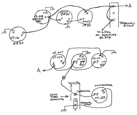
BC-348 but still maintaining its high level of performance. The "later"
version reduced production costs by simplifying the construction and
component mounting which additionally made depot repairs of these
"later" receivers much easier. The "later" circuit used two RF amplifiers, a
converter stage, three IF amplifiers, a duplex diode/triode provided
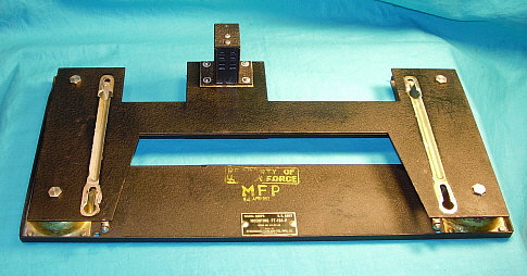
Detector, AVC and BFO functions and a 6K6 provided the audio output.When the receiver was installed on its FT-154
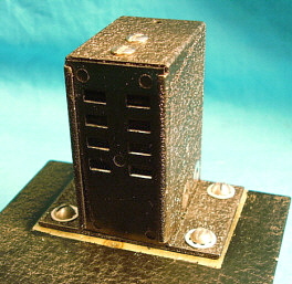
shock mount and installed in the aircraft, an eight pin Jones plug mated
with a receptacle and cable that exited from the rear of the mount
containing the 28vdc input, the remote stand-by relay function and an
audio output line. The BC-348 was generally interconnected with the
transmitter to control boxes allowing the
transmitter's control relay to provide antenna switching, receiver
stand-by and providing side tone monitoring which allowed for full
"break-in" keying.
Since there are so many variations, military
radio collectors have generally divided the BC-348 into two groups,
"early" types (B, C, E, H, K, L, O, P & R) referred to as the "Grid Cap
Tubes" version based on the types of tubes used in the receiver. The "later"
versions (J, N & Q) are referred to as the "Single-Ended Tubes" version,
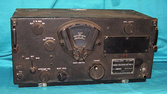
again based on the types of tubes used in the receiver. Many different contractors built BC-348s but
Wells Gardner & Co. probably built the greatest quantity of receivers and
is the most commonly seen contractor-manufacturer. Estimated production
of the entire BC-348 line exceeds 200,000 receivers making it one of the
most commonly found WWII aircraft receivers today. Towards the end of
WWII, radio equipment that was used by both the Army (USAAF) and
by the Navy were assigned "Army-Navy" designations and the
BC-348, in particular the J, N and Q versions and the R
versions, were designated as the AN/ARR-11. It's unlikely that
any of the BC-348 receivers actually had their data plates changed
(I've never seen an AN/ARR-11 data plate.) However, I had a
BC-348-Q SN:20966 that had an Army-Navy orange-ink stamp just
below the band switch. A photograph of SN:20966 is shown in Part
3 of this write-up. Unfortunately, the "AN - Army-Navy" stamped
was very faded and didn't photograph well, it can be seen but
just barely. This "AN - Army-Navy" stamp probably was the only
indication that might have been applied on a BC-348 that was used by the Navy.
That "A-N" might have
been listed in some Navy procurement book somewhere as an AN/ARR-11.
The BC-348 became available as surplus almost immediately after WWII
ended. The typical price was around $100 for a receiver that was in its
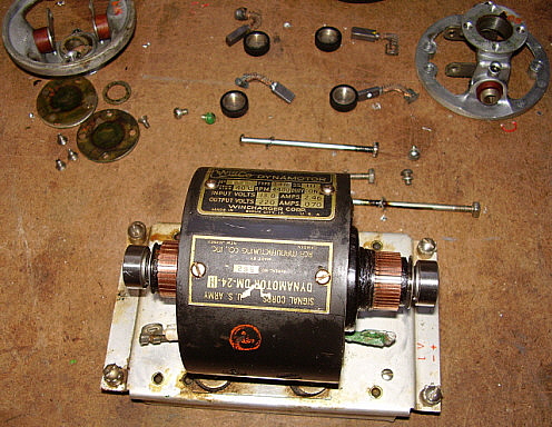
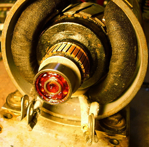
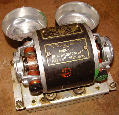
original crate and about $50 for a receiver that was in good-used condition. The dynamotor was
still installed in all receivers offered at the time but many surplus dealers
were offering to replace the
dynamotor with an AC power supply for around $15 extra. The actual AC
power supply conversion was fairly simple and the operation of the
receiver usually wasn't compromised other than probably adding some hum
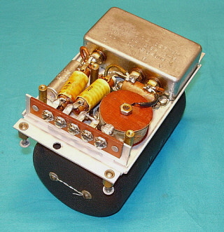
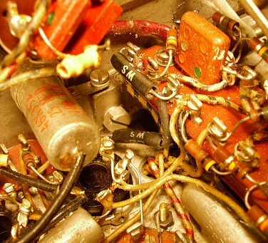
to the audio output. All of the
dealer power supplies were built with the
cheapest parts available, used a simple pi-filter and were undoubtedly
built and installed as quickly as possible by technicians possessing
limited abilities.
Since most surplus dealers added an AC power supply to the BC-348 (and every surplus conversion book
advocated this modification along with many other "ham-type" mods,) nearly every ham-owner
thought they were capable of converting the receiver into anything that was
considered necessary for successful operation. The upshot is today it is
almost impossible to find a BC-348 that hasn't been modified in some
manner.
There were at least two
different types of military conversion AC power supplies that show up
occasionally. Hallicrafters produced an AC-operated power supply that could be added
to the BC-348 by the military. It was designated as EP-298. Very few
ever show up so the production quantity must have been very small
(uninstalled examples turn up occasionally.) The
only installed example I've seen photos of was of a BC-348 used by the Navy. It's
likely that the AC-operated BC-348 requirement was post-WWII and was
probably for surveillance or some other ground-based application. The Hallicrafters' EP-298 would have required some conversion rework to the
BC-348 and the installation would have been performed by depot higher echelon level
technicians. The second type of military AC-operated BC-348 is the version used
by the Air Force designated as the BC-348-S. The contractor was Belmont
Radio who, apparently, rebuilt BC-348 DC-receivers into a very limited
number of these AC-operated versions for ground use. The contract was
post-WWII.
Many BC-348s
owners actually do want to operate their receiver on the AC house line.
Nowadays, an all-original, dynamotor equipped BC-348 should NEVER
be converted to AC operation. Original receivers are very rare. However,
at least 98% of the surviving BC-348 receivers have already been
converted to AC,...they just need a little help to achieve the great
performance the BC-348 is capable of.
Almost always this must involve rebuilding the existing AC power into a
unit that filters properly and provides the required negative bias
voltage (that many surplus dealers and ham-sters forgot about.) A
well-designed AC power supply must have the following,...dual section
filtering (two filter chokes) for reducing hum to the imperceptible
level. The power transformer CT and negative filter capacitor returns
must connect to B- and B- should not be connected to chassis for proper filtering
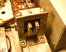
and proper bias voltage. The AC power supply must be
turned "ON" by using the AVC-MVC switch (as original.) The proper SO-143
connection must be utilized for the AC input. If possible the PL-103 plug
and FT-154 should be utilized. If these suggestions are incorporated in
the AC power supply design and the receiver is given a thorough rebuild
and a full IF/RF
alignment that includes proper adjustment (or repair) of the Crystal Filter operation, the performance of
the AC-operated BC-348 will be excellent (better than the original
dynamotor operation) and the receiver can become an
easy-to-use asset to the mil-rad station. Plans for dual section
filtered, AC power supplies are in Part 3 of the article.
Today, with the
increasing popularity of hams running completely military radio
stations, the BC-348 is often being used as the station receiver.
Sometimes this is because the original military configuration requires
its use, other times because the operator knows that it's such a great
performing receiver - a receiver that "does so much,
so well, with so little." Fabulous military looks, excellent sensitivity and
good selectivity (when the IF is properly aligned and you actually use
the Crystal Filter) have made the BC-348
a favorite among the military radio enthusiasts, knowledgeable hams and
collectors of WWII airborne radio equipment.
|