Radio Boulevard
Western Historic Radio Museum
 
HAMMARLUND MANUFACTURING CO.,INC.

"The Incredible 'Super-Pro' Receivers"
(1935 to 1948)


Information Contained in Part 1  -  Production History of the Comet & Comet-Pro, the Super-Pro Designations
The SP-10, The SP-100, The SP-200, The Military Super-Pros, The SP-400, Power Supplies & Cables,
 
Serial Numbers, Production Estimates, Serial Number Log

Information Contained in Part 2  -  Engineering Changes, Expected Performance,
  Guide to Restoring the Super-Pro Receivers,
 Restoration of the WMI SP-10 Receiver, Restoration of the SP-100X Receiver

Information Contained in Part 3  -  Restoration of the SP-100LX,  
Rebuilding the SP-400-SX, Photo Gallery of Collector's Super-Pro Receivers
COMET-PRO - details in Appendix A at the end of Part 3
HQ-120X & RBG RECEIVERS - details in Appendix B at the end of Part 3
 

by: Henry Rogers WA7YBS/WHRM

photo: QST ad 1-38, Stan Wolff of the NY Herald Tribune copying Press with the 'Super-Pro' - this is an interesting ad in that it shows both the SP-10X (right) and the SP-100X (left) models.

Was the Hammarlund Super-Pro the ultimate pre-WWII communications receiver? The advertising of 1937 stated it was "The Last Word" in communications receivers. Other advertising called it "Tomorrow's Receiver - Today."  Its build quality was second-to-none. As Hammarlund said about designing the Super-Pro, "...at no time was cost considered a limiting factor."  Hammarlund wanted to build a "standard" by which other communications receivers were measured. The Super-Pro was advertised as an "amateur-professional receiver" and it had several unique features that did set it apart from its contemporaries. These included a virtually sealed precision tuning assembly with custom designed variable condensers and a cam-operated knife-switch type 360 degree rotation bandswitch, variable-coupled air-tuned IF transformers that allowed a continuously adjustable IF bandwidth and a powerhouse, high fidelity audio output. In the hands of an experienced operator, the Super-Pro could out perform any other receiver. Listing at $400 and selling at discount dealers for about $250, not many Depression-era hams could afford the Super-Pro, so not much was ever written about the receiver in ham magazines. As a result, among hams, opinions are highly diverse when it comes to the Super-Pro's performance capabilities. The best pre-war receiver? Let's see,...    H.Rogers, Feb 2008

The Incredible 'Super-Pro' Receivers

PART 1
 

Hammarlund's Company History up to 1931

Oscar Hammarlund came to the United States from Sweden in 1882 to work for the Elgin Watch Company. By 1886, he had gone to work for Western Electric in Chicago. He later worked for the Gray National Company on the Teleautograph machine and finally, in 1910, formed his own company, Hammarlund Manufacturing Co., Inc. At first the company built gadgets but they soon became involved building Western Union call boxes. An interest in wireless led to the Hammarlund designed variable condenser which became an industry standard for quality. In the mid-twenties, Hammarlund formed a temporary partnership called Hammarlund-Roberts specifically to supply Hammarlund-built parts for broadcast radio kits. As home radio technology improved, the popularity of radio kits declined and Hammarlund-Roberts Co. folded. That certainly didn't affect the operation of Hammarlund Manufacturing Co., Inc., in fact, they were just coming out with their newest creation, a shortwave radio that was going to push the few communications receiver manufacturers of the time into the superheterodyne building business.


The Comet and the Comet-Pro  -  1931 to 1935

Hammarlund's entry into the shortwave and ham receiver market began in 1931 with the introduction of the Comet All Wave Receiver. The early Comet circuit used eight tubes, plug-in coils (without shields) and operated with a built-in AC power supply. However, what was important was that it was a superheterodyne. In fact, the Comet is generally credited as the first successful commercially-built shortwave superhet, introduced at a time when almost all shortwave receivers in use were TRF with regenerative detectors. The Pilot AC Super Wasp was typical of type of short wave receivers in use at the time and the Comet was superior in all comparisons. Of course, the Pilot Super Wasp had been a kit and was considerably cheaper than the Hammarlund Comet. Also, most of the hams at the time built their own receivers that were usually simple and inexpensive. The Hammarlund Comet was beyond what most hams at the time could "homebrew."

By late-1932, the Comet had evolved into the Comet-Pro and this version of the receiver changed the way in which commercial users, the military and the amateurs listened to shortwave signals. Hammarlund described the Comet Pro in their advertising as "The World's Finest Shortwave Receiver." It really wasn't an exaggeration, the Comet Pro was a superbly built, great performing receiver - at least when compared to the other receivers of the early thirties. Up to the introduction of the Comet-Pro, the Regenerative Detector with a couple of TRF stages ahead of it was thought to be the most sensitive receiver on shortwaves. The superheterodyne, while fine for AM Broadcasts on medium wave, was too noisy and that lowered its usable sensitivity - at least that was what most shortwave radio enthusiasts thought. Hammarlund took the challenge to build a shortwave superhet that had low internal noise and was sensitive. By careful design work using quality parts and construction, the Comet-Pro did achieve what was thought impossible - a usable shortwave superheterodyne receiver. As the Comet evolved to the Comet-Pro, it was fine-tuned into an excellent performing communications receiver that became quite popular, ultimately being found in many ham shacks of the thirties and also used by many professionals, including the military. Some Comet Pro receivers even made it to the Arctic and Antarctic with various expeditions.

By 1934, the Comet Pro was beginning to show its age. Its limitations were due to the lack of an RF amplifier, making the Comet-Pro susceptible to images as the received frequency was increased. Some users would add an after market pre-selector to eliminate the image problem. Other issues included lack of a calibrated dial readout, a BFO control that was a "swing-arm" lever accessed under the lid and the fact that changing bands required changing a set of two plug-in coils. The competition was beginning to displace the Comet Pro from its number one status. National had come out with their AGS and FB-7 receivers and was busy designing their fabulous HRO. Patterson had the PR-10 with a matching preselector available and Radio Manufacturing Engineers had their RME-9 receiver with a TRF amplifier built-in, direct frequency readout on the tuning dial and an "R" meter. No doubt, Hammarlund wanted to return to the days when they offered the only "high performance" receiver available. The Hammarlund engineers had been at work on the Comet Pro's successor since 1933.....  More information on the Comet Pro receiver is in Appendix A at the end of Part 3 of this article.

photo left: Comet Pro ad from Radio News February 1933

The 'Super-Pro' Production History

photo above: Right page of the QST ad from March 1936

Designing the 'Super-Pro' began in 1933 when Hammarlund announced it was working on a new shortwave receiver dubbed the "Comet Super-Pro." At that time there were only a few superheterodyne shortwave communications receivers on the market - National had their AGS and FB-7 receivers and Patterson may have just introduced their "All Wave" predecessor to their PR-10. However by 1935, several manufacturers such as  Breting, Patterson, RME and RCA had all come out with fine quality superhets, not to mention that National had released their fabulous HRO receiver. As the competition continued to build better and better receivers, Hammarlund, still in the design stages, continued to improve the concept of what the 'Super-Pro' would be. That Hammarlund wanted to produce the best communications receiver available cannot be denied. A receiver that would appeal to engineers, professionals and well-to-do hams. Quality of construction would be of the highest caliber and performance would be to the limits of the design possibilities of the day. By March 1935, Hammarlund dropped a hint that the Comet Super-Pro would be released soon but the year went to conclusion with no formal announcement. By June 1935, Hammarlund was supplying a Super Pro receiver, the SPA, to the Signal Corps. Finally, in the March 1936 issue of QST, a full two page ad announced the "Super-Pro" receiver. A personal letter from Lloyd Hammarlund accompanied the detailed introduction advertisement. By the thirties, Lloyd Hammarlund was generally running things at the company although his father, Oscar Hammarlund was still company president (Oscar H. died in 1945.) The introduction told about the great Super-Pro features and showed what the receiver looked like, inside and out. Touted as an "Amateur-Professional Receiver" no where in any advertising is the price ever mentioned. Listing at $400, the Super-Pro was one of the most expensive of the generally available communications receivers in the mid to late thirties.

photo above: Left page of the QST ad from March 1936

The Super-Pro Features - With the availability of the new Super-Pro receiver hams and commercial users now had a communications receiver that boasted several innovative features. The precision that was designed and built into the RF tuning unit was incredible. 25 coils mounted on 20 Isolantite (a type of ceramic material with low loss characteristics) bases working with a Hammarlund-built 4 gang tuning condenser and 12 gang bandspread condenser along with a custom designed cam-operated knife-switch type bandswitch made up the heart of the RF tuning unit. The main tuning dial featured band-in-use masking. The antenna input coils have a Faraday shield between the primary and secondary to keep the input impedance constant regardless of tuning. The bandspread condenser has three different sections per gang that optimizes the variable capacitance needed for 90% span on the 80, 40 and 20 meter ham bands. The RF box is an entirely shielded, nearly sealed metal box and only connects to the IF/AF chassis with eight wires (and the four grid leads.) The receiver tuned from .54 up to 20MC in five bands. Bandspread was provided for the upper three tuning ranges. Another innovation was the variable-coupled air-tuned 465KC IF transformers that were part of the continuously variable Selectivity control. With this control, IF bandwidth and audio fidelity were adjustable from 3 KC out to 16 KC. Of course to take advantage of this, a full fidelity, high power audio amplifier was provided with a transformer coupled, triode-connected, push-pull audio output delivering about 14 watts of power. An Amplified AVC system was used for maximum control of the RF/IF gain when listening to SW-BC stations or local AM stations. A "Tuning Meter" measured the total IF amplifier plate current and, as strong carriers increased the AVC bias, the IF gain was reduced and the meter would read less current. The operator tuned for the lowest meter reading while tuning in an AM signal. There was a procedure for logging the "no signal" noise level current and then measuring the tuned signal current and then calculating the "db over the noise" as a signal report - Hammarlund thought all hams and engineers carried a slide rule in their pocket! Also included was a front panel controlled Beat Oscillator (BFO,) a Tone control along with separate RF, IF and AF gain controls. 14 tubes were used in the receiver. The separate power supply used two tubes, a 5Z3 B+ rectifier and an 1-V rectifier for the bias supply.

photo left: Super-Pro ad from QST July 1936 - CE William Greer, WNEL, where the Super-Pro was used to rebroadcast WABV

Super-Pro Designations - When the Super-Pro was first introduced it was just referenced as "The Super-Pro" as there was no need to distinguish it from any other receiver. Throughout its pre-WWII evolution and production, Hammarlund advertising always referred to the receiver as "The Super-Pro," "The New Super-Pro," "Series 100/200 Super-Pro" and it was never referred to by a "model number."

"The Super-Pro" quickly evolved with different frequency ranges, crystal filter options and speaker size options becoming available and these options had to be designated or identified when the receiver was ordered or sold. To this end, Hammarlund created a Code (an option code) that identified a specific set of options that were to be (or were) incorporated into a specific Super-Pro receiver. For example, an "X" suffix designated a crystal filter option while an "S" suffix referenced the ham version of the receiver. The prefix was modified to designate a rack mount receiver by adding "R." A rack mount, crystal filter optioned Super-Pro would be ordered as "SPR-10-X." The 12" loudspeaker was a special order item and apparently not designated by an option code. In ALL Hammarlund ads the receiver was "The Super-Pro" but in most documentation, such as schematics, SP-10 was used.

By the time the "Series 100 Super-Pro" was introduced, several options were available. They were designated by the following Option Codes:

For Series 100 Super-Pro supplied with 10 inch loudspeaker

SP-110 - .54 to 20mc, no crystal filter
SP-110-X - same as above, with crystal filter
SP-110-L - 100-400kc, 2.5-20mc, no crystal filter
SP-110-LX - same as above, with crystal filter
SP-110-S - 1.25 to 40mc, no crystal filter
SP-110-SX - same as above, with crystal filter

R is added to end of prefix, e.g. SPR-110-X, which would indicate a rack mount receiver with 19" panel, crystal filter and 10" speaker.

For Series 100 Super-Pro supplied with 12 inch loudspeaker

SP-120 - .54 to 20mc, no crystal filter
SP-120-X - same as above, with crystal filter,...,etc.,..., you get the idea.

There were  24 different Codes describing the various options available for the Series 100 Super-Pro. These are not Model numbers. They're Codes that describe how a receiver was optioned. The receiver didn't have a model number - it was identified as the "Series 100 Super-Pro."

With the Series 100 Super-Pro, with all of it's possible options, it became more apparent that Hammarlund was using their option code "SP-110-X" as a "basic" identification for all versions of the Series 100 Super-Pro within their manuals and on their schematics. ALL Hammarlund advertising still referred to the Series 100 receiver as "The New Super-Pro" or "Series 100 Super-Pro" but never with a model number (since one really didn't exist.) But, the Code "SP-110-X" soon became the commonly used document identification for any of the Series 100 Super-Pro receivers. Since Rider's Perpetual Troubleshooter's Manuals weren't experts in Hammarlund Codes, they used "SP-110-X" to index their documentation - after all, that's how the Hammarlund owner's manual referenced the receiver. In contrast, many of the radio dealers of the time began using the correct Hammarlund Option Code numbers, since it accurately described the particular receivers they were selling. Hammarlund realized the confusion that the Codes, model names and numerous variations of identification was causing. It was obviously an error on Hammarlund's part to identify the Series 100 Super-Pro receiver documentation with a "basic" Code designation that would obviously change depending on the options selected by the purchaser. Hammarlund tried to correct their mistake with the Series 200 Super-Pro.

With the Series 200 Super-Pro, Hammarlund started to refer to the receiver as the "SP-200-X" in all manuals and on all schematics. Since ALL Series 200 Super Pro receiver were equipped with crystal filters, they ALL had the "X" option. Also, since the receivers came with either a 10" or 12" speaker, there really wasn't an option code that used "200." So, the basic "SP-200-X" used in Hammarlund documentation doesn't change regardless of other options included in a receiver that the docs were supplied with. To further clarify, Codes were specified as "CODE" in all listings and the number of option combinations reduced to 12. However, as seen in the table shown, Hammarlund titled this "SUPER-PRO MODELS,..." and then goes on to show Code numbers in the first column. It's no wonder the confusion continued.

For the most part, WWII corrected the designation code confusion since, after 1942, virtually all receivers went to the Signal Corps who eventually gave all Super-Pro receivers a military designation that simplified receiver identification (but even the SC gets confused in TM11-866.) Post-WWII, the SP-400-X and SP-400-SX were still advertised as the "Series 400 Super-Pro" but "SP-400-X" or "SP-400-SX" was engraved right on the receiver's front panel. Only two basic versions were available. Loudspeakers were supplied but size wasn't specified. Rack mounts were available, since the receiver already had a 19" panel, and the designation "SPR" was to be used to specify "rack mount" and "SPC" was used for the table cabinet version.

The SP-10 and SP-200 were generally used as the numerical "Series" designation. The post-WWII SP-400 and SP-600 also follow the numerical "Series" designation. Only the "Series 100" receivers deviating from that standard. In this article, I reference ALL Super-Pro receivers to the numerical "Series" that they belong to. This eliminates the confusion of the two different speaker size options changing an unofficial model number of two, otherwise identically optioned Super-Pro receivers. The SP-110-X or SP-120-X will be identified as the SP-100-X, that is, belonging to the "Series 100 Super-Pro," since this follows Hammarlund's own resolution used for the Series 200, 400 and 600 Super-Pro documentation.


The "Super-Pro" from 1936 to 1945


The "Super-Pro"   1936

Officially introduced in the March 1936 issue of QST magazine*, initially the SP-10 was just called the "Super-Pro" - there was no need to distinguish it specifically since there were no other models. The SP-10 option code started to be used as soon as additional options were offered. SP-10 became a convenient way to refer to the early Super Pro. The first production Super-Pro used all glass tubes with vented tube shields on all tubes except the audio section tubes. The tube lineup was RF - (2)6D6, Mixer - 6A7, LO - 6C6, IF - (3)6D6, DET - 6B7, AVC - 6B7, BFO - 6C6, 1st AF Amp - 76, AF Driver, P-P AF Output - (3)42. The power supply used a 5Z3 for B+ and a 1-V for the bias.

The push-pull amplifier was capable of 14 watts of high fidelity audio power. The AF output transformer was specified in some sources as a 600 ohm Z line audio (Rider's, for instance.) However, the SP-10 manuals specify that the output Z is 8 ohms and the schematic contained in the manual marks the output as "Speaker Voice Coil."  But, there is also another published SP-10 schematic that shows an added phone jack output along with the phones and speaker terminals with resistors added in series in the audio output line. Unfortunately, there are no values shown for the components on the schematic. One could assume since the audio output line is marked "600 Ohm Line" that the resistors comprise somewhat of a match when used with the standard 8 ohm Z output transformer secondary. The speculation is that the audio output transformer was always an 8 ohm Z secondary and no real change ever took place. It's the same transformer with the resistors added for 600 Ohm Z and the resistors not installed for 8 ohm Z, (so far, all SP-10 receivers encountered have an audio output Z of 8 ohms.) Connections were on the rear apron of the chassis and were heavy-duty fiber-mount pin jack sockets for earphones and the phono input and screw terminals for speaker. The phono input allowed the user to access the high fidelity, high power audio amplifier. Additionally, there are separate RF, IF and AF gain controls along with a Tone control. None of the controls had any sort of calibration or reference scales.

* The SPA receiver was the SP-10 produced for the Signal Corps in June 1935 - see more details in "The Military Super-Pro" section below

photo above: The original Super-Pro from 1936, later designated as the SP-10

The Tuning Meter was more than just a signal strength indicator. Since it measured total IF amplifier plate current, it could also indicate when the IF amplifiers were being overloaded by too much RF signal. It was able to cope with a variety of RF and IF levels and still maintain a useable indication. Additionally, it also would function on CW which meters that functioned off of the AVC line couldn't do. The meter wasn't illuminated. The tuning dial featured a rotating dial mask that was gear driven by the bandswitch and provided a "band-in-use" tuning scales. Three variable coupled 465KC IF transformers were used in the adjustable Selectivity control. The spring-loaded plunger from each IF transformer is cam adjusted by levers mounted under the chassis. The Selectivity shaft is also spring loaded to provide a "positive feel" to the control. In addition to the front panel adjustable IF Selectivity, the Input and Output IF transformers to the detector and the Output transformer for the amplified AVC had adjustable coupling. The adjusters were knurled nuts on threaded shafts the protruded out the tops of the IF cans. The user could set the detector bandwidth for optimum selectivity for the receiver's particular service. The use of Input and Output IF transformers along with a 6B7 duplex diode-pentode tube for a second detector-IF amplifier resulted in the SP-10 actually having four IF amplifier stages and ten tuned IF circuits.

Within a few months the "S" version was announced in QST. This receiver tuned from 1.2 to 40MC, so hams had available to them a Super-Pro the would tune in all of the amateur bands from 160M to 10M. Additionally, the bandspread was changed to allow its use on all tuning ranges. This version was advertised extensively in the ham magazines during the last half of 1936.  There was also a Crystal Filter ("X" option) now available. The Crystal Filter mounted in the upper left part of the panel with the 465KC crystal assembly and the phasing condenser mounted to a small panel with an on-off switch and a scale for the phasing condenser. The front panel had to have a cut out to allow the Crystal Filter panel and assembly to be mounted.   >>>

>>>  It is interesting that none of the advertising artwork ever shows the early Super-Pro with the Crystal Filter option installed. The power supply provided terminals for connection of the speaker field coil. The SP-10 power supply provides slightly lower B+ voltages than the later supplies but the difference is less than ten percent. An electrodynamic speaker was included in the purchase price but it was just a speaker - no housing was provided. The standard speaker was 8" in diameter but for an extra $25 a deluxe 12" speaker could be purchased. The SP-10 only had the front panel SEND-RECEIVE toggle switch for putting the receiver into standby.

It is apparent that engineering changes were incorporated into the SP-10 receivers through out its short nine month production. Perhaps the earliest change was to the biasing of the 2nd Detector Input amplifier grid (6B7.) This change added a resistor to the bias series resistor string by changing the 600 ohm resistor to two 300 ohm resistors which allowed the bias voltage to be slightly increased by moving the connection to the junction of the two 300 resistors. This arrangement is also found in the later SP-100 receivers. The BFO circuit was also changed to have a parallel grid capacitance rather than capacitance to ground connection. Additionally, the BFO plate load resistor was changed from a 5K resistor to a 50K resistor, though this may have been a parts list error that was corrected in the SP-100 series. The most visible change was the elimination of the Tone control, which was incorporated towards the end of the SP-10 production. Hammarlund probably believed that very few of the Super-Pro owners were using the Phono input for phonograph record reproduction and therefore the Tone control was unnecessary since for radio reproduction the Selectivity control would do about the same thing - limit the higher audio frequencies. The SP-10 series was in production for about nine months and the total number produced was probably around 500 receivers. Though the list price was $400, most discount dealers sold the SP-10 for around $250.

The SP-10 and Front-End OverloadingHammarlund stated in the SP-10 manual that it was possible to overload the front-end of the receiver by tuning in very strong, local signals and advancing the RF gain too much while in AVC.  The manual even gives an example of what to expect if the RF Gain was advanced further than necessary when receiving local signals. The overloading was especially likely if an efficient antenna system was used on the two lowest frequency bands. The fact that the RF Gain can be advanced sufficiently when receiving strong signals to cause overloading and the fact that Hammarlund does cover this in the manual seems to suggest that it was a deliberate part of the SP-10 design. Hammarlund's engineers did re-vamp the RF-IF Gain control circuit and replace the adjustable Detector and AVC transformers for the new SP-100 Series, making it seem likely that they were aware of the ease at which users could misadjust the SP-10. The engineering changes to the SP-100 eliminated the overloading while in AVC issue. Today, there is no evidence that overloading was a common "problem" experienced by SP-10 users when it was new. Over a period of time, component degradation, modifications, changes in wiring layout and mechanical assembly due to repairs will certainly affect how well an SP-10 functions today. By loosening the screws on the bottom cover of the RF Tuning Unit, one can easily induce RF overload and distortion with just a slight advance of the RF Gain control. Also, poor solder joints in the RF AVC line will accomplish the same thing due to improper AVC control of the RF amplifiers. There is no evidence that the SP-10 had overloading problems when new and to accomplish overloading required substantial misadjustment or modification of the receiver.  >>>

>>>  As an example, the SP-10 shown in the photo below once was in use at WMI. It was modified and repaired over the years and after its tenure at WMI it was further modified and repaired in a "creative" manner that changed the much original wiring layout and component placement. This SP-10 did easily overload on strong signals in AVC, so much so that the RF gain bias source was changed by a former owner to help solve the problem. However, after a complete "rebuild to original" of the receiver that included returning to the original wiring layout and the original component placement along with complete (correct) mechanical assembly, this SP-10 now performs flawlessly, exactly as the manual describes it should operate. That is, when tuned to a strong local AM BC station (10KW 15 miles away,) using an efficient BC band antenna (outside 50ft end fed wire,) with the RF Gain at maximum in AVC, some distortion is apparent. However, by reducing the RF Gain to about 50% the overloading is eliminated and so is the distortion (just as the manual states.) When the SP-10 is connected to my 135' tuned dipole, I can tune in the same AM BC station and have the RF Gain at maximum with no distortion at all. This is due to the inefficiency of  the tuned dipole at AM BC frequencies reducing the level of the input signal, thus the RF Gain can be substantially higher. This is exactly how the manual describes the operation of the SP-10. This should establish that the SP-10 was designed to be a highly adjustable receiver, able to cope with many different types and levels of signals. That it might be misadjusted was assumed by Hammarlund engineers and those conditions were described in detail in the SP-10 manual. But then,...who read the manual? 


Shown above is a 1936 SP-10 sn: 576. This Super-Pro was used at WMI, a ship-to-shore station located in Lorain, Ohio on the shores of Lake Erie. This receiver has been completely rebuilt and restored to original "as delivered to WMI" in 1936. Its terrific performance has tremendous audio range and incredible sensitivity. The variable selectivity is totally rebuilt and functions great.

 
 Photo above: WMI operating room in 1937. Note the three SP-10 'Super-Pro' receivers in the racks. SN:576 is certainly one of the receivers in the racks. Note in the central rack, directly below the Super-Pro, is a highly modified Hammarlund Comet-Pro.

  Photo from: Inland Marine Radio History Archive  -  here is their URL:  http://www.imradioha.org/WMI.htm


The Series "100" Super-Pro   1937-1939

photo above: Introduction advertising for the new SP-100 Series - QST, January 1937

The new Series "100" Super-Pro was introduced in January 1937. It upgraded the receiver's front-end by changing the large glass tubes there to metal octal tubes. The two RF amplifiers were now 6K7 types. The mixer was a 6L7 and the local oscillator was a 6J7. Also, the audio section was changed over to metal octals with a 6C5 1st AF amplifier with a triode connected 6F6 driver and push-push, triode connected 6F6s for the output. In all, eight tubes were changed over to metal octals while the IF amplifiers remained 6D6s, the 2nd Detector and AVC amplifier remained 6B7s and the BFO remained a 6C6. The power supply B+ rectifier remained a 5Z3 and the bias rectifier was changed to a type 80.

Other changes were elimination of the separate RF and IF gain controls. The RF and IF stages' bias lines were combined to use a single manual control labeled "Sensitivity."  The Sensitivity control could also adjust the AVC bias line more negative than the AVC control bias and therefore reduce the overall gain while still maintaining AVC control above that point. The variable coupled Detector and AVC transformers were replaced with fixed-coupling units. Since there were now no moving parts in these transformers, the component boards that had been mounted under the chassis of the SP-10 were relocated inside the Detector Output transformer can and the Amplified AVC Output transformer can. The elimination of the separate RF and IF gain controls and the variable-coupled transformers for the Detector and AVC were probably due to the ease at which the SP-10 could be misadjusted, resulting in overloading and distortion. The Selectivity control, as it was called on the SP-10, was renamed as a Band Width control. The Tone control was also dropped because the user could limit the audio highs by reducing the IF bandwidth. Actually, it is likely that the Tone control was eliminated on the later production of the SP-10.

The BFO and Bandwidth controls were given front panel calibrated scales. Even the Sensitivity control and the Audio Gain were given reference scales. Internal changes also included different AF transformers that were vertical mount, frame-type (non-potted) units with the AF Output transformer having a single 8 ohm output Z. These were new style audio transformers and not the same style potted 8 ohm Z transformers that were installed in the late SP-10 production. Since a switch was provided for "Speaker" or "Phones" the earphone Z is rather low. A 600 ohm line audio was not provided in the SP-100 series except for perhaps the very late versions of the SP-100LX version. The standard speaker size was changed to 10" with the introduction of the SP-100. The AVC also could be used for CW as a large time constant capacitor (.25uf) is switched into the AVC line when the receiver is switched to CW. Today, this actually works very well for receiving SSB with the AVC on, BFO on and the Sensitivity advanced for good AVC action (around 8.) The AVC will control the front end gain and allow a good ratio of signal level to BFO injection so the SSB signal will demodulate without distortion. I routinely listen to SSB in this manner with my SP-100X and LX receivers. Of course, the receiver can also be used in "Manual" control for maximum sensitivity in the CW mode.

The SP-100 series still used the "Tuning Meter" that measured total IF amplifier plate current resulting in a "backwards" operation of the meter. The 0 to 5 scale on the meter actually has ten divisions for each numeral - 50 divisions total. The push-pull audio remained at the same power capabilities of 14 watts and a Phono input was still provided as a rear connection. A "Remote Relay" operation of the B+ was added to the rear chassis. The input is via pin terminals and the function parallels the operation of the "Send-Receive" switch. When the Crystal Filter option was installed in the SP-100, the first IF transformer was changed from a variable-coupled unit to a fixed coupled transformer with leads brought out the front for connection to the crystal holder mounting and the phasing condenser. Whether this was the case with the earlier SP-10 is not known as most examples of that receiver don't have the Crystal Filter installed.

The Super-Pro's antenna input Z is around 115 ohms. This was approximately the impedance of the twisted pair antenna feed lines that were popular for dipole antennas. Since the Super-Pro doesn't have an antenna trimmer control, Hammarlund expected the user to provide a matched antenna. Most professional users and most knowledgeable hams provided matched antennas but shortwave listeners sometimes used end fed wires or inverted "L" antennas with no matching device. The normally high impedance of these antennas didn't match the Super-Pro input Z and the common result was higher noise level along with weaker signal strength.

The cabinet for the early Super-Pro and the SP-100 is really nothing more than a dust cover that is secured with eight knurled thumb nuts on the front and three thumb screws on the rear. There is a metal identification tag mounted on the back of the dust cover with places for the receiver type and serial number to be stamped however most of the time these are stamped with some kind of factory identification code - usually two letters. Serial numbers usually do match on the dust cover and the chassis. The bottom cover has small metal-cup, felt-center feet mounted in each corner. This gave the user a table top cabinet.  The panel is 18" across on the table top models. A 19" rack-mount model was available and, with the Crystal Filter option included, the list price was nearly $450. The front panel on early, pre-WWII Super-Pro receivers is made of  .190" aluminum. This was black wrinkle finished first, then engraved. This resulted in the nomenclature looking bright silver.

The model designators used with the SP-100 Series were as follows: SP-100 covered .54 to 20mc and had no crystal filter, SP-100L covered 100kc to 400kc and 2.5 to 20mc, SP-100S covered 1.25 to 40mc. If the crystal filter was added to any version then an "X" suffix was added. Hammarlund's ordering department needed to specify which size speaker was to be included with each receiver package ordered. To this end, when ordering a Super Pro, the ordering code "SP-110" indicated that the 10" speaker was to be included and "SP-120" indicated that the 12" was to be included. Even though the speaker size that was included as part of the entire receiver package seems to modify the actual receiver model number, that number is the "ordering code" and is specified as such in many documents. Additionally, that ordering code number is never stamped into the metal tag on the back of the receiver dust cover. Hammarlund advertising always referred to the receiver as the "Series 100 Super-Pro" or "The New Super-Pro."

Photo above: Article-ad from POPULAR MECHANICS  12-37 promoting the Super-Pro SP-100SX for 10 meter coverage. This article shows that the speaker included was just that - a speaker - no cabinet was included. Note also that this article never refers to the receiver by its model number - it is only a "Short-Wave Super De Luxe."

Rider's Perpetual Troubleshooter's Manual mentions the SP-100LX version and indicates that it substituted the 2.5 to 5.0mc band with a 150kc to 300kc band. This is in direct conflict with the Hammarlund "SP-110L" manual (that is available on the BAMA site.) That manual indicates the coverage is 100-200KC and 200-400KC and 2.5-20MC in the remaining three bands. This is the standard "L" coverage, even for the later Series 200 Super-Pro. However, even some of the SP-200 advertising also mentions the 150KC-300KC tuning range. There may have been some special orders with that frequency coverage but no known examples exist. The standard production provided 100kc to 400kc covered in two ranges.

Another interesting "L" feature, shown in the BAMA site manual, is dual secondary windings of the output transformer (600/8K Z) and a front panel "Phone" jack for the phones. This became the standard for the later SP-200 models. Up to this time (2021) it's impossible to confirm the unique features of the LX version because no collectors have reported serial numbers from a SP-100LX. Our SP-100LX receiver isn't an original example and was an amateur conversion from a standard X version so it can't be relied on for confirmation.

This is what appears to be standard,...the SP-100LX tunes from 100kc to 400kc in the first two bands and from 2.5mc to 20mc in the highest three bands. Only the three highest frequency tuning ranges have bandspread capabilities. One note,...Hammarlund was continually upgrading the Super-Pro throughout its production. There is the possibility that is shown in the BAMA manual that the dual secondary (600/8K Z) audio output and front panel phone jack may have been incorporated into the LX versions.

There is another interesting SP-100 variation that has been reported by SMØAOM. This receiver is known as the MRM-5, or Markradiokottagare 5, and it was sold only to government customers in Sweden. The receiver is an SP-100 but the frequency coverage is 200kc to 400kc and .54mc to 10mc. The receivers were available in either rack mount or table top configurations. SMØAOM has two examples, sn 1352 and a partial sn 16xx. The Swedish translation manual is dated October 1937.

The SP-100 series was in production for about two years and nine months. Though the list price was over $400, most dealers sold the SP-110X (ten inch speaker included) for around $250. Total number of SP-100 Super-Pros produced was probably around 1200 receivers.


Photo above: 1938 SP-100X Super-Pro (SN: 3387) - This receiver originally belonged to Pacific Gas & Electric Company in California. Since it was owned and maintained by PG & E, it was never modified and was only repaired as necessary. See Part 3 of this article about our authentic restoration of this great example of the SP-100X.


The Super-Pro Console   1938


Beginning in July 1938, Hammarlund offered a customized Series 100 "Super-Pro" receiver in a floor standing console cabinet. The cabinet included doors that closed over the receiver panel and a 15" speaker with a bass reflex port. The receiver panel was faux finished walnut and had gold tone nomenclature along with brown knobs. The meter housing and dial escutcheons were trimmed gold and the dial masks were amber color instead of black. To assure that the receiver would appeal more to the shortwave listeners and home radio users, Hammarlund eliminated the front-panel control of the BFO, making it an internally set adjustment. The Crystal Filter option was not installed either. Also, the "send-rec" switch was eliminated. Otherwise, behind the panel the SP-150 receiver was a standard SP-100 series set. SP-150 was probably used for the option code because of the 15" speaker installed in the console.


What must have sounded like a great idea to Hammarlund, considering the success of Scott and McMurdo Silver high performance receivers, turned out to be a sales flop. The SP-150 was a superb receiver that was really never appreciated by very many people in the radio buying public. It just wouldn't do for hams - it had no BFO on the front and it was too big. It didn't have the Scott or McMurdo chrome chassis - how could you impress your friends? The rather plain cabinet couldn't compare to the flamboyant creations from Scott or McMurdo. As a high priced console, the SP-150 couldn't find many admirers even though it performed as well as (or better than) any Scott or McMurdo and had a more accurate dial readout. Only 69 were ever built, making it one of the most difficult Super-Pro receivers to find.


Shown in the color photos is the SP-150 owned by John Howes. The Super-Pro receiver is serial number 3055 and the power supply is serial number 3105. This example of the Super-Pro Console is in original condition.
 

photos supplied by: John Howes


The Series "200" Super-Pro   1939-1945

photo above: The cover of the operator's manual for the Series "200" Super Pro receiver

Introduced in October 1939, the Series "200" thoroughly modernized the Super-Pro to 1940 receiver design concepts along with a reduction in the build-cost of the receiver. The SP-200 is a more conventional approach to superheterodyne design, especially in the IF section of the receiver. The SP-200 used three IF amplifiers with standard 465KC IF transformers (except for the two variable coupled units for Band Width control) and the 6B7 duplex diode-pentode detector-IF amplifier of the proceeding Super-Pro receivers was replaced with a standard duplex diode 6H6 tube. The AVC circuit was also  simplified using capacitive coupling rather than an inductive pickup and reducing the transformers to one unit. All of these changes were a cost-to-performance decision resulting in a receiver than performed as well as its predecessors but was much less expensive to build. The list price reflected these changes by a reduction to $315.

The circuit now used all octal tubes replacing the glass tubes of its predecessor with metal tubes. Tube lineup was RF-(2)6K7, MIX-6L7, LO-6J7, 1IF-6K7, IF-(2)6SK7, DET-6H6, NL-6N7, AVC AMP-6SK7, AVC REC-6H6, BFO-6SJ7, 1AF-6C5, 1AF&P-PAF-(3)6F6, B+ REC-5Z3 and Bias REC-80 ... 18 tubes in all. Additionally, the "200 Series" did away with the IF current "Tuning Meter." Now the S-meter was illuminated and had a 0 to 9 scale. The meter operated from the AVC line so it worked normally instead of "backwards." Undoubtedly, the old tuning meter's complicated method using the "delta" of signal versus noise calculation to give the "db over the noise level" had almost everyone confused. Complaints must have been common and ultimately prompted the change to a standard S-meter. A new Noise Limiter was incorporated into the circuit. It was a "clipper" type noise limiter. The Crystal Filter assembly was now entirely installed inside the first IF transformer. Also, instead of only a Phasing adjustment, a five-step Selectivity control was added. Now, for the first time, the Super-Pro was installed inside a real metal cabinet with hinged lid and carrying handles and the front panels were standard 19" rack width on all models . The cabinet will have a metal ID tag mounted on the back and sometimes a model type will be stamped, or perhaps a serial number, but many times these tags were never stamped at all. If the model type is stamped in, it usually is "200" and a letter suffix to further identify the receiver, e.g., "200X."

The "200 Series" evolved slowly. The first evidence of change is in the SP-100 front panels no longer using the large square cut-out for the Crystal Filter panel. Instead, the Crystal Filter assembly is mounted directly to the front panel with just holes for the controls.  Next, were the four toggle switches for AVC/Manual, Speaker/Phones, Send/Receive and Mod/CW. Some very early "200 Series" may have all four switches, but quickly the Send/Receive and Mod/CW switches are changed to rotary switches with knobs and the position of the Send/Receive switch is changed. Finally, the Speaker/Phones switch is replaced with an earphone jack. With the earphone jack change, the audio output transformer also changed to a dual secondary outputs and sometime later both audio transformers became potted units (as the original SP-10 was.) The dual audio outputs provided 600 ohm Z line audio to drive a matched speaker and a separate Hi-Z winding to drive earphones or other Hi-Z device. The dual secondary windings and the front panel "Phone" jack features were also found on the SP-100L versions but, for some reason, not on the first SP-200 receivers. Though the layout of the receiver is very similar to the SP-100, the underside of the chassis uses different component mountings and the shield between the RF and IF sections was removed.

The three versions of the SP-200 are the SP-200X, tuning from .54 to 20.0MC. The SP-200SX, tuning from 1.2 to 40MC. The SP-200LX, tuning from 100 to 400KC in two bands and 2.5 to 20.0MC in three bands. Like the SP-100 series, the Hammarlund sales literature uses the ordering code "SP-210" if the version ordered came with the standard 10" speaker or "SP-220" if the version came with the deluxe 12" speaker. Although a loudspeaker was included with the receiver, a speaker cabinet wasn't. The PSC-10 matching speaker cabinet listed for $8.50 (1941 price.) Special "universal" power supplies could be ordered for operation of 115vac or 230vac.  

photo above: The Series 200 Super-Pro as pictured in the 1941 Hammarlund Catalog. This artwork shows the Speaker-Phones switch found on early versions.


photo above: An artwork image of the SP-200-X chassis from the 1941 Hammarlund Catalog showing the early version frame type audio transformers. These were later replaced with potted transformers.


SP-200-SX


SP-200-X

Sales literature also sometimes indicates that the LX version covered 150 to 300KC substituted for the 2.5 to 5.0MC band (usually expressed as wavelength in meters.) Interestingly, Rider's also lists this coverage for the SP-100L version. Most likely these are both errors. The earliest known SP-200LX (at present,) SN:8423, tunes 100-400KC and 2.5-20.0MC or the standard coverage for the LX. An error in the 1942 sales literature indicates that all versions had bandspread on all five tuning ranges. Actually, this only applied to the SX version, the X and LX bandspread is only on the three highest tuning ranges. Earlier advertising had phrased the statement as "bandspread throughout the entire high frequency range of the receiver" which is technically accurate.

The photo to the upper-left shows the 1939 Series 200 Super-Pro SP-200SX sn: 6230, covering 1.2 to 40MC. This is a very early version with frame-type audio transformers and using the toggle switch for selecting either "phones" or "speaker." The front panel is .190" thick aluminum that is black wrinkle finished and then engraved to have the nomenclature appear bright silver. Note on the S-meter - though this meter appears to be similar to the S-meter shown in the artwork images of the early SP-200, there is considerable doubt that this is an original meter. It has obviously been rebuilt in the past using parts from two different meters. It is more likely that the full glass front style was standard for production until the later military contracts. Interestingly, the metal tag on the back of this receiver cabinet is stamped "200SX" as the model number. 

Just before WWII started, the .190" thick aluminum front panel was changed to a .125" thick steel front panel. When the front panel became a steel fabrication, the paint used changed to a smooth-finish, semi-gloss black. Additionally, the nomenclature was stamped into the panel and then filled with white paint. Most of the steel panels are copper-nickel plated on the front side only - to prevent corrosion and subsequent problems with the paint. All Super-Pro panels, from SP-10 through the military SP-200, are painted on the front side only. The back of the panel is always left unpainted.

The photo lower-left shows the later version of the Series 200 (SP-200X sn: 9419) with the smooth finish, semi-gloss black steel panel. Also, the standard S-meter housing with full glass front is shown on this receiver. Note that the toggle switch for "Speaker-Phones" is replaced with a single .25" phone jack indicating that the dual output audio transformer is installed. Since the new steel panels were .125" thick steel, spacers were installed on the various mountings to compensate for the different thickness of the panel. It seems likely that all of the civilian Series 200 Super-Pro receivers probably had black panels. The tag on the back of this receiver's cabinet was left un-stamped which is common with many Super-Pro receivers.

During WWII, government agencies like the FBI used the Series 200 Super-Pro at their listening posts and most likely these receivers were the civilian models. When the demand increased during WWII, some variations in the front panel paint color appear, especially those receivers that were destined for the Signal Corps (which was primary military user.) Grays, Green-Gray and Blue-Gray are the most commonly seen colors. Civilian Super-Pro production is difficult to estimate because found examples indicate that sales of these versions continued though the early part of WWII - at least to 1943. It's likely that only a very small percentage of the wartime production was destined for non-military use and then it is likely that certain government agencies were the only users. SP-200 non-military production is probably around 1500 to 2500 receivers. Confusing this production number is the fact that the military did purchase communications receivers early in WWII for use in the war effort. These receivers are sometimes re-tagged and will have Signal Corps stamps. Hammarlund serial numbers will identify when the particular SP-200 was built and if the tags or stamps post-date the serial number then the receiver was probably "drafted" into military service. Even SP-100 versions were commonly found "in use" by the military during WWII.

It is very common to find some variations in the SP-200 Series receivers but whether this is due to production stock variations, special orders or subsequent repairs using later stock parts can't be verified accurately without a physical inspection of the receiver to determine the originality of the parts or assembly in question. 


The Military "Super-Pro"   1935-1945

The Super-Pro was selling to the military on a small scale before WWII. In June 1935, the U.S. Army Signal Corps ordered the new Super-Pro receiver under contract (order) number 10932-NY-35 with the receiver designated as the SPA. Although this contract is nine months ahead of the official QST announcement in March 1936, it seems likely that the SPA was delivered long before the civilian versions were available. The SPA was essentially the SP-10 version of the Super-Pro with a military data plate mounted on the front panel. By about 1936, the SPA was upgraded to Signal Corps requirements but still using the same 1935 contract order number with the same issued date. While the early SPA was virtually identical to the SP-10, the later SPA version had several changes incorporated into its circuit. Audio output impedance was changed to 600Z ohms. An extra choke was added to the power supply to sub for the field coil speaker allowing the use of a PM speaker with 600Z matching transformer. The "Speaker-Phones" switch was replaced with a front panel phone jack that was in parallel with the 600Z audio output. The antenna impedance was increased to 300Z ohms. As with the earlier versions, these later SPA receivers didn't have crystal filters and a military data plate was installed on the front panel.

It's likely that the SP-100 was also built to Signal Corps needs and some examples of the SP-100 receiver will be found with Signal Corps acceptance stamps and sometimes MFP application and stamps. Certainly the Signal Corps was buying the SP-100 but there doesn't seem to have been a specific model especially built for Army contract purchases. There are some indications that later versions of the SP-100LX had the Signal Corps requirements as the standard build.

With the SP-200, the early military versions (pre-WWII) are acceptance stamped but have no special designators known, similar to the SP-100. It's likely that the same general changes from the standard model were incorporated into those receivers going to the Signal Corps. Since all SP-200 receivers included a crystal filter, the Army versions will also have crystal filters. Though the civilian SP-200X receivers had the "Speaker-Phones" switch, it's likely that those going to the Signal Corps had the 600Z phone jack installation. The volume of Super Pros going to the military increased dramatically with the start of WWII. Early WWII versions are similar to the pre-war military SP-200 receivers in that no special designators were used. Acceptance stamps are usually the only indication of military service.

By 1943, the military versions were being identified by their US Army Signal Corps designations. The "X" was known as the BC-1004, while the "LX" was the BC-779. The least seen version is the "SX" which was known as the BC-794. There was another version shown in the military manuals, the R-129/U. This receiver seems to have been very poorly documented since it's low frequency coverage is shown as 300kc to 550kc and its IF is specified as 465kc. It's highly unlikely that the R-129/U had the low frequency coverage specified since it conflicted with the standard 465kc IF. It's more likely that the R-129/U covered 200kc to 400kc and .54mc to 10mc with the 200kc to 400kc coils being installed in place of the 10mc to 20mc band. This version would have used standard Hammarlund components.

Sometimes the end user also would require special designations. In particular, Allied users may have required special designations. There are usually suffixes that designate which power supply came with the receiver. The WWII Super-Pros were sometimes built by contractor Howard Radio Company, though the great majority of Howard-built Super-Pro versions seen are the BC-779 and power supply there are known examples of "Howard-built" BC-1004 receivers also. Under the chassis the changes to the circuit mostly involve component types. Seventeen of the individual paper-wax capacitors are replaced with metal container units - the so-called "bathtub" capacitors that usually contain multiple capacitors inside the housing. It is likely that the 1943 and later civilian (government) models also had the "bathtub" caps installed. These "bathtubs" are mounted on the inside wall of the chassis in the RF/IF area. Additionally, there are a few tubular oil-filled capacitors used. The chassis may be MFP'd and "application dated" depending on its service.   >>>


photo above:  The 1935 Hammarlund SPA Receiver built for the Signal Corps U.S. Army on contract number 10932-NY-35 dated June 29, 1935, nine months before the official announcement in March 1936 QST magazine. Although this image is artwork and not a photograph, it's obvious that the SPA is the SP-10 with a military data plate mounted on the front panel.  Artwork is from "Instruction Book for Super-Pro - Manufactured by Hammarlund Mfg. Co,.Inc., New York, NY, USA - published by authority of The Chief Signal Officer  -  Order No. 10932-NY-35 Date June 29, 1935."  (Yes, I do have the original SPA book)

>>>  The standard "BC" receiver was a rack mount unit with a dust cover that was secured by eight thumb nuts on the front and three thumb screws on the rear. Dust covers are painted black wrinkle finish. Though the majority of "BC" receivers are rack mounted units, sometimes the receiver would be installed in the military CH-104-A cabinet. This cabinet is similar to the SP-200 civilian cabinet except there are no decorative chrome strips installed. When the receiver is installed in the CH-104-A cabinet, the dust cover holes in the front panel are usually filled with screws and nuts. CH-104-A are found in either black or gray wrinkle finish.


photo above: ASP-1004 Receiver - 1945 version of the BC-1004

After 1943, there weren't very many changes required by the military, so these WWII Super-Pro receivers are basically the same as the civilian-government versions, under the chassis. Front panels are different on the WWII Super-Pro, especially late in the war. Many of the panels were painted various shades of gray. Some of the later 200 Series receivers will have a greenish-gray paint on the front panel of the receiver and power supply. There are numerous variations in the color-mix, with some models tending to be more blue-gray. Certainly the highest production quantities for all of the pre-war and wartime Super-Pro receivers are the military versions with total production of several thousand units of each type. Total production was probably at least 10,000 receivers. Signal Corps TM-11-866 covers the most commonly seen versions of the military Super-Pro.

Shown in the photo left is one of the later WWII Super Pro receivers with the greenish-gray front panel paint. This one is designated as "ASP-1004." Many of the WWII Super-Pro receivers were used by our Allies. Does the prefix "ASP" = Allied Super Pro? Interestingly, under the tag, the panel is ink stamped "BC-1004" but there are no Signal Corps stamps anywhere on the receiver.

The U.S. Navy never used the Super-Pro receivers. A very important part of Navy shipboard radio operational uses were in the 400kc to 500kc part of the spectrum and the LX version didn't tune those frequencies. Hammarlund certainly didn't want to re-engineer the variable IF transformers and the LO/Mixer coils and that would have been required in order to move the IF from 465kc to some other frequency that would allow 400kc to 500kc tuning. Hammarlund must have been content with the Signal Corps U.S. Army contracts for the Super-Pro since they never designed a Super-Pro receiver that the Navy contracted until the SP-600/R274B and Hammarlund didn't build a receiver that covered the 400kc to 500kc part of the spectrum until the SP-600VLF receiver from 1955.

Without doubt, the primary user of the Super-Pro was the Signal Corps. Even post-WWII Hammarlund advertising states that ", Super Pros were standard equipment in practically every Army Airways Communications System installation throughout the world." Some Super-Pros were used for surveillance or intercept purposes operated by the Army. Shown in the photos left and right are two Super-Pro stations. Left shows for communications and the right is for intercept.


photo left: The Manila, Philippines radio communications link to Tokyo. Photo is dated August 20, 1945. Note the BC-221 Frequency Meter. This unit provided an accurate way to measure the frequency the Super Pro was tuned to. Judging by where the dial mask is, the "TOKYO" receiver is set on the 10-20MC band. Power supplies are on top of the receivers and three receivers and four power supplies are visible.      photo from C. Cusick, KØDWC collection


photo right: The intercept station at the Yakutat Air Base in Alaska during WWII. Three SP-200 receivers are in use and one SP-100 receiver (with the black panel.) Judging by where the dial masks are, the two left side receivers are set to the same band while the right side receivers are set to different bands.  Note the unusual rack mounted speaker panels at the top of the racks.     photo from Fred Bryan, www.oftencold.com

Allied-Built Versions of the Super-Pro SP-200


Some countries built their own military versions of the Super-Pro. In particular, the Australian company, Eclipse Radio, built the AMR-200 which is nearly a perfect copy of the SP-200.

The Russians produced the KV-M which is built like a Super-Pro but without the bandspread dial. The chassis layout and especially the RF box are very close copies of the SP-200 Super-Pro. Shown in the photo to the right is a KV-M receiver. This one has an addition of  a small lamp that is mounted to the front panel.

See references at the bottom of this webpage for links showing photos of the AMR-200 and other photos of the Russian KV-M receivers. Thanks to Steve Bringhurst for the AMR-200 and KV-M information.


Post-WWII Use of the WWII Military Super-Pro Receivers

R-270/FRR - Component Receiver for AN/FRR-12

 Customized BC-794 by:
 Wickes  ENGINEERING & CONSTRUCTION CO.

The R-270/FRR receiver started out as a standard WWII BC-794 receiver. It's likely that some of the military Super-Pros were never shipped or, if they were, were never put into service by the end of the war. After WWII, the Signal Corps was interested in developing RTTY communications to the point where it was virtually "error-free." Diversity reception assured that the incoming signal didn't fade thus providing the RTTY TU with a fairly constant level input signal (dual diversity can reduce fading by up to 90%.) The R-270/FRR is one of the component receivers of the AN/FRR-12 Dual Diversity Receiver built by Wickes Engineering & Construction utilizing customized-rebuilt Hammarlund BC-794 receivers. While dual diversity practically assured that the received signal remained constant, it didn't help with receiver frequency drift due to LO and BFO instability (which the Super-Pro was famous for.) Wickes incorporated a selectable Crystal Oscillator that could be switched in to replace the LO. Of course, the receiver had to be also manually tuned to the correct operating frequency so the RF and Mixer stages would be "in-tune." The operator could also tune in the Crystal Oscillator harmonics with the Main Tuning which would then have the correct RF and Mixer tuning for harmonic operation. To prevent drift from the BFO its operating frequency was also crystal controlled. The output from the two R-270/FRR receivers was taken from the IF output (provided by Wickes' modifications.) This was routed to a Diversity RTTY Demodulator, the CV-31A/TRA-7 that accomplished the diversity combining via its internal circuitry. Once set-up, the AN/FFR-12 could provide virtually "error-free" RTTY.

The R-270/FRR was rebuilt and customized in 1948 by Wickes Engineering & Construction Company for the U.S. Army Signal Corps. The contract date on the Signal Corps data plate on the front panel tag is 1947 (and the manufacturer is shown as "Wickes ENGINEERING & CONSTRUCTION CO.") but the MFP coating is date-stamped "OCT 1948." The custom modifications consist of adding a three channel crystal oscillator that can be selected from the front panel via a switch that provides Crystal Oscillator OFF/ON function plus the channel selection. Also, on the small Crystal Oscillator panel, which is located above the main tuning dial escutcheon, is a vernier frequency control. The Crystal Oscillator modification is the same as Signal Corps "Improvement Kit" MC-531 which is shown in TM11-866. MC-531 is the forerunner to the JX option in the SP-600 receiver and functions in a similar manner. If the Crystal Oscillator is ON, its plate voltage is derived from the B+ that is switched from the LO plate, thus disabling the LO. When the Crystal Oscillator is OFF, then the B+ is routed to the LO plate.   >>>

>>>  You must have a crystal installed that is at +465kc from your desired receive frequency and then you also have to manually tune the receiver to the desired receive frequency, otherwise the RF stages and the Mixer will not be in tune (which is exactly how the SP-600JX works.) The actual crystal frequency used will depend on the desired receive frequency (band used) and whether or not the crystal is going to be operated on the fundamental or on an overtone. 

Additional Wickes' custom modifications were to replace the AVC rectifier tube (6H6) with a 6SN7 dual triode. This provided the AVC rectification and also provided a triode buffer output for the IF OUTPUT. Also, the AVC Amplifier tube was changed from a grid cap 6K7 to a single-ended 6SK7 and the BFO tube was changed from a grid cap 6J7 tube to a single-end tube, the 6SJ7. Additionally, the second and third IF amplifier tubes where changed from grid cap 6K7 tubes to single-ended 6SK7 tubes.

Further changes included a new front panel made out of aluminum with raised lettering (rather than the Hammarlund engraved or stamped lettering.) Also, the standard steel bottom panel was replaced with an aluminum bottom cover that had the receiver schematic applied to the inside. IF transformer cans were replaced if the associated tube was changed to a single-ended tube.

The AN/FRR-12 manual (TM11-896) indicates that the receivers could also be used for diversity CW or AM. If CW was going to be used then the BFO crystal (462.45kc) had to be removed and the BFO "re-aligned" to function as a standard BFO. The user also had to "short out" the crystal socket with a jumper wire. Like the SP-600, the R-270 was modified by Wickes to use a "twin-ax" connector for the antenna input. Additionally, a CT was provided on the audio output transformer (labeled as "600-0-600" - although this nomenclature actually indicates that the 600 Z ohm output is across the entire winding, not each side of CT.) The entire chassis and shields were giving an extra heavy coating of MFP, which is typical of later, post-WWII Signal Corps equipment.

The power supply provided was the R-74A "Heavy Duty" military style. This was the later version with the 5U4 and 5Y3 rectifiers. The interconnecting power cable was also heavy duty and rubber jacket insulated. The power supply is also heavily MFP'd and date stamped DEC. 1948. The power supply bottom cover has the schematic on the inside of the cover.

The Wickes' R-270/FRR is certainly more than just a "modified" Super-Pro receiver. I would call it "customized and rebuilt" for the Signal Corps requirements for drift-free and fading-proof RTTY reception. The quality of workmanship, both mechanical and electronic, is superior and what would be expected from a professional engineering company. If one didn't know how the standard Hammarlund WWII Super-Pro receivers were built, the Wickes' "Custom Super-Pro" could easily be mistaken for Hammarlund factory workmanship. Performance is identical to the Hammarlund receivers with the exception that several optional outputs and frequency control circuits are available. Audio is still excellent, sensitivity quite good and the variable IF coupling provides excellent control of the bandwidth.


The Series 400 Commercial "Super-Pro"   1946-1948

Hammarlund introduced their post-war, updated version of the Super-Pro in 1946. The receiver had many subtle changes to reflect Hammarlund's intent to market the SP-400 as a commercial receiver (it's part of its designation according to the 1947 ad shown to the right) and not as a military receiver. Remaining unchanged was the variable-coupled IF system to provide 3kc to 16kc infinitely adjustable selectivity. However, the IF was ultimately changed from 465kc to the standard 455kc (it's probable that some of the very early examples will have the 465kc IF, although this may have only been on the SX versions.) The audio stage was originally using one triode-connected 6F6 driver and two triode-connected 6F6 tubes in push-pull for the audio output. Some sources indicate that this changed later in production to one 6F6 driver and two 6V6 tubes in push-pull for the audio output. I haven't found any specifics as to how the 6V6 tubes were connected - triode or as beam-power pentodes. The audio output power specifications were lowered to 8 watts (from the 14 watts claimed for the SP-200) and the output impedance changed from 600Z to 500Z. The tuning range was changed to either .54mc to 30mc for the "X" or 1.25mc to 40mc for the "SX." This was probably to reduce the complaints of the older Super-Pro's coverage of .54mc to 20mc for the standard "X" model necessitating having the "SX" model if frequencies between 20mc to 30mc (or 40mc) were of interest. The old multiples of tuned bands, e.g. 1.25-2.5mc, 2.5-5.0mc., 5.0-10.0mc, etc., was changed on the "X" version to allow .54mc to 30mc coverage in five ranges while the "SX" ranges remained unchanged (since it had the same frequency coverage as its predecessor, the BC-794.) The RF box remained virtually unchanged except for the slight tweaking of the "X" frequency coverage. Also, band spread was now on all tuning ranges. Inside the circuit, all .01uf capacitors were eliminated with only .05uf or .02uf capacitors used. Gone were the military, multi-unit oil-filled, tub-mounted capacitors, replaced with discrete paper-wax capacitors. Many of the resistors used were JAN A-B type. All controls were in the same location as the SP-200. At a glance, the top of the chassis could easily be mistaken for a 200 Series Super-Pro. 
 

Shown to the left is the Series 400 "Super-Pro" ad from the 1947 ARRL Handbook. Note that the IF is not specified in the ad.

Cosmetically, the SP-400 was given a face lift reflecting the post-WWII styling trend of using gray finishes applied to communication equipment. The WWII steel front panel material was returned to the aluminum panels that had been used earlier. Some front panels used engraved nomenclature while others were silk-screened. Some panels were smooth gray paint while others were gray wrinkle finish. The paint used was of inferior quality and its durability was low at best. The front panel identifies the receiver as "SP-400-X" or SP-400-SX" in addition to "Super-Pro."


The styling of the knobs was changed to very small, rounded pointer knobs and two very small round tuning and bandspread knobs. These miniscule knobs resulted in severe panel wear due to the operator's fingers dragging across the panel as the knobs were rotated (the same problem is found in the HQ-129 that used the same types of knobs.) The panel problems were directly related to the inferior quality of paint and the non-ergonomic nature of the small knobs. The cabinet is exactly like the late-WWII versions with gray wrinkle paint and lacking of any stainless trim pieces. Carrying handles were mounted on the sides.
 

Rack mount versions were offered with the SPR prefix to the ordering code number while the table models used the prefix SPC in its ordering code. A loudspeaker was included with the receiver but not a cabinet for said the speaker. The speaker cabinet was identified as SC-46 and sold for $5.25 list. The SP-400 listed for $342.
 

photo right:  SP-400-SX  SN: 4-1249

The SP-400 is the oddity of the Super-Pro models. It's obvious that the military wasn't interested in the SP-400 as evidenced by the lack of any military contracts issued. Also, the Wickes Engineering modified BC-794 (R-270/FRR) indicates that the Signal Corps decided to modify the WWII versions of the Super-Pro for their specific needs rather than buy the new version of the Super-Pro that didn't have the necessary features. It's well-known that during this post-WWII time period Hammarlund was working very closely with the Signal Corps developing a new type of receiver that was going to meet the military's increased communications and intercept requirements demanded by post-WWII world events. So, perhaps Hammarlund wasn't interested in any Signal Corps contracts for the SP-400 either since the receiver was designated as a "Commercial Super-Pro Receiver."


Hammarlund had built the SP-400 for commercial users although it was also advertised in some ham publications. Certainly its high selling price would have restricted its availability to affluent hams. Of course, the commercial market and the rich hams weren't going to produce many orders for the SP-400. As far as any military contracts, the Signal Corps was waiting for the new Hammarlund's new Super-Pro, the SP-600. The SP-600 was announced in Hammarlund advertising as early as 1948 and, in that same year, production of the SP-400 was stopped.


Photo to the right shows the top chassis of the SP-400-SX sn:4-1249. It's almost identical in appearance to its predecessor, the SP-200. Note that the back side of the front panel is painted - a first for the Super-Pro receivers.

As far as performance, the SP-400 is every bit as good of a receiver as the late-military versions of the Super-Pro had been. In fact, it has better frequency coverage on the "X" version and the audio seems to have more bass response. Also, the "X" version had band spread is on all tuning ranges. Unfortunately, C-D TIGER paper-wax caps are used throughout the circuit and that will require rebuilding for top performance. Luckily, only a handful of TIGERs are hidden with four located inside the Amplified AVC can, three inside the RF box and one in the Crystal Filter box. All other components are of dependable quality.


The SP-400 was considered a flop. It didn't sell all that well. It was too expensive for most hams and those hams that could afford its $342 selling price were buying Collins gear instead. The circuit changes were minor and basically left Hammarlund's post-WWII 'Super-Pro' working exactly like the 1939 SP-200 receivers. The cosmetic changes ended up causing the SP-400 to age gracelessly, becoming an ugly, unwanted relic around the ham shack. The SP-400 was just a "stop-gap" for Hammarlund while they worked with the U.S. Army Signal Corps in designing the new 'Super-Pro' - the SP-600. The SP-600's success and longevity of production seems to confirm that Hammarlund was directing all of their effort towards their "real" post-WWII receiver, the SP-600. As usual for Hammarlund, their lethargic engineering pace resulted in their new post-WWII receiver not being ready for production until 1950.


Photo left shows under the chassis of a SP-400-SX after a rebuild. Obvious are the Sprague Orange Drops.


Super-Pro Power Supplies and the Power Cable

All of the various power supplies that were built for the Super-Pro are similar in design and similar in the voltages provided to the various models of Super-Pro receivers. There were three levels of B+, +385vdc, +270vdc and +140vdc that were specified for the SP-200 series. The tube heater supply is 6.3vac and the C bias is -50vdc. The early receivers, the SP-10 and the SP-100 used power supplies that provide slightly lower B+ voltages with +365vdc, + 260vdc and +110vdc indicated in the manuals. The bias voltage isn't specified in these earlier manuals but it is in the range of -45vdc to -50vdc. All of the various types of power supplies route the voltages to the receiver through a four foot cable that has a ten spade lug connector that screws to the ten pin terminal strips on both the power supply and the rear of the receiver chassis. Usually the metal box, protective covers that mount over the terminal strips on both the power supply and the receiver chassis will be missing. The SP-10 power supply used a type 1-V rectifier tube for the bias supply. This tube was replaced in the SP-100 supply with a type 80 rectifier tube. The HV rectifier was a 5Z3 until about 1944. Late power supplies will use a 5U4G and a 5Y3G rectifier tubes.

Early power supplies used with the SP-10 and SP-100 will have a small second terminal strip with two screw connections marked "Field" for the electrodynamic speaker that was provided with these receivers. With some late SP-100 and all of the SP-200 power supplies, a large choke with a DCR of 1100 ohms was included in the power supply to replace the field coil of the electrodynamic speaker and allow the use of a PM speaker. The standard power supply had a metal box cover with louvers that protected the tubes. The power supplies were usually placed on the floor near the receiver. Rack mount power supplies have a 19" panel screw mounted to the front of the chassis and a metal cover over the top of the chassis with lugs the protrude out the front panel for the cap nuts. Bottom covers were standard on all types of power supplies. Metal cup, felt center feet are usually mounted at the corners of the bottom cover for non-rack units. Some rack mount units will have the felt feet included.


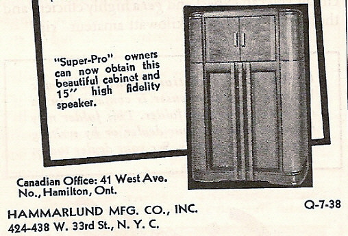
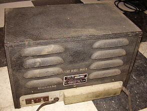
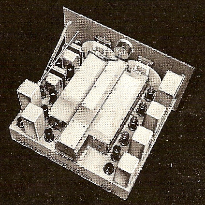
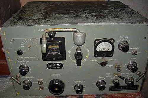
SP-100 PS SN:3388 - Note the two terminals for the field coil of the electrodynamic speaker


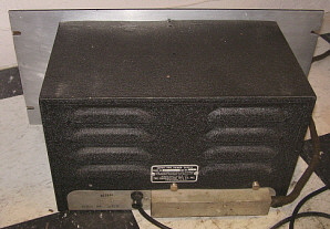
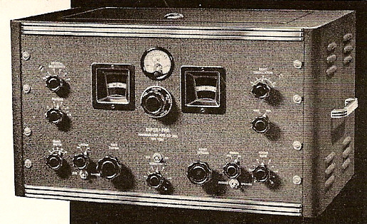
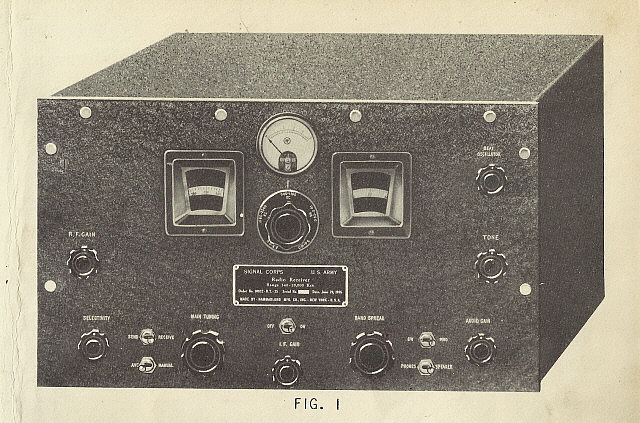
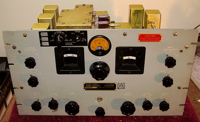
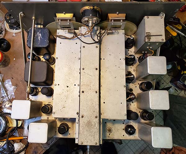
photo above: SP-200 PS Rack Mount - Note that the terminals for the speaker field coil have been eliminated


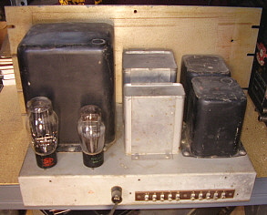
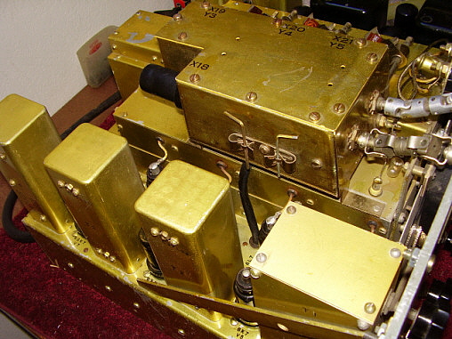
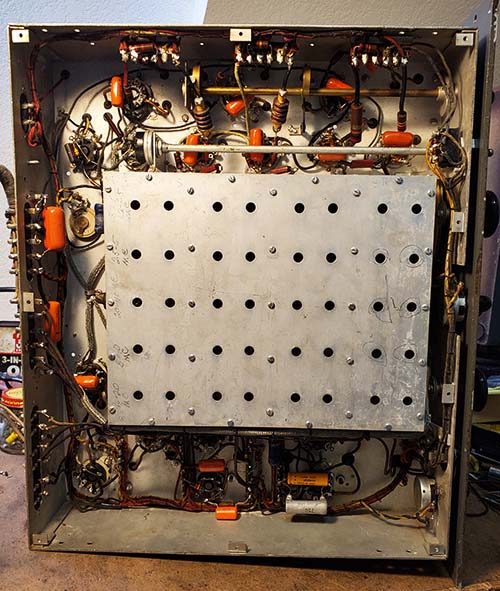
photo above: ASP-84B PS Military Rack Mount

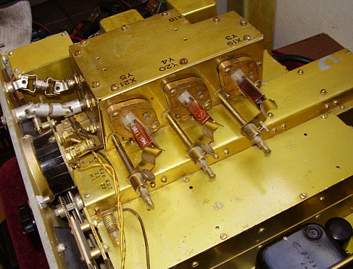
Most of the military Super-Pro power supplies will have an oversize potted power transformer and potted chokes with oil-filled filter capacitors. Some of the late-version military supplies went to can-type oil-filled paper capacitors. About this time the rectifiers were changed to a 5U4G and a 5Y3G. All of the military supplies were normally expected to operate in continuous duty service so the size of the power transformer was substantially increased. Some of the military power supplies will have dual primary power transformers for 115vac or 230vac operation. Military power supplies for the Signal Corps are usually identified as RA-74, RA-84 or RA-94. RA-84 is for 115vac operation only. The RA-74 is a heavy duty, multiple primary power supply and the RA-94 is the heavy duty, dual primary power supply. 
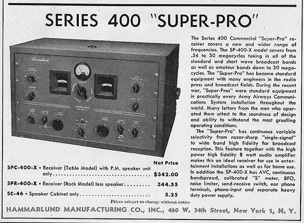
The SP-400 power supply is very similar to the non-military versions of the SP-200 power supplies. Rectifiers used were the 5U4G and the 5Y3GT. Frame transformers and chokes are used. Electrolytic filter capacitors are used. Output terminals and power cable were not changed.

Fortunately, almost any of the Super-Pro power supplies can be used with almost any Super-Pro receiver. Considerations would have to be made for the field coil connection on early supplies but the voltage output terminals and the voltages present are nearly the same for all power supplies and receivers. Care should be taken when using a SP-200 power supply with either the SP-10 or SP-100. The tubes used in the audio of the SP-10 are 42s and the SP-100 uses 6F6 tubes. The maximum plate voltage is +375vdc on either type of tube. The SP-200 also used 6F6 tubes and ran +385vdc at the connection terminals and assumed +380vdc at the tube. But, the tube's maximum plate voltage is referenced to the cathode voltage which is around +15vdc and that implies that the plate-to-cathode voltage is around +365vdc which is fine. The 750 ohm cathode resistor didn't change in value in any of the series so the increase from +365vdc in the early power supplies to +385vdc in the SP-200 supplies was probably viewed as a "safe" increase that resulted in slightly more audio power. You can use a SP-200 power supply for testing the SP-10 or SP-100 but for long-term operation of either type of receiver, the correct power supply should be used. However, it's easy to modify a SP-200 supply by adding a 220 ohm 5 watt series resistor in the +385vdc line to provide slightly lower Audio Plate B+ voltage. The advantage of always using a modified later power supply with either the SP-10 or SP-100 is the elimination of the electrodynamic speaker requirement. These earlier supplies utilized the field coil of the speaker as a filter choke but later power supplies already have a choke installed so a permanent magnet speaker can be used. The SP-200 power supply can be used to power a SP-400 receiver with no modifications.

Unfortunately, since just about any Super-Pro power supply can be used with just about any Super-Pro receiver, very few matched set-ups are found today - that is the sequentially serialized receiver/power supply. With the SP-10 and SP-100 receivers, the original power supply serial number is one off  from the receiver serial number. The assignment of a sequentially serialized power supply to a specific receiver ended by the time the SP-200 was introduced in 1939.

The Super-Pro power cables normally encountered are usually a nine wire, cloth covered cable with a special, spade-lug type terminal strip connector on each end. These cables were used on the later SP-200s and the military receivers. Some military power cables are shielded and have rubber jacket insulation. Later nine wire SP-200 cables have tube heater wires that are of a larger gauge wire than the remaining seven wires. The tenth lug is not used on these terminal strips. On early cables, there are usually nine wires that are all the same gauge. If a tenth wire is present, it is "switched to ground (chassis) connection" that operates with the ON-OFF switch. It is not used in the circuit as supplied but was provided as a spare function for possible user applications. The switched ground operation is on most Super-Pro receivers but the actual wire in the cable is seldom present unless added by a former user. Many Super-Pros will be missing their original power cable but the cables are easy to make. Just observe that the tube heater connections, pins 1 and 2, use about 12 to14 gauge wires while the remaining wires can be 16 to 18 gauge. The cable length is approximately four feet. The connections to the power supply match the receiver, 1 to 1, 2 to 2, etc. It isn't necessary to have the terminal strip connectors but they do make connecting and disconnecting the receiver and power supply much easier. The correct orientation for an original power cable is to have the spade lugs pointing down and the cable to exit the protective cover on the right side. 
 

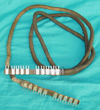
photo right: The power cable from a military SP-200 Series Super-Pro receiver-power supply showing the unique spade-lug type connector strip


Hammarlund Super-Pro Serial Numbers and Estimated Production

From examining many pre-WWII Super-Pro receivers along with several HQ-120X receivers and Comet-Pro receivers, it appears that Hammarlund issued serial numbers in a new sequence starting with "1" (or some low number) beginning with the first SP-10 receiver and continuing in sequence right through the military versions built during WWII. Since the earlier Comet Pro receivers all have much higher serial numbers and were all built before any Super-Pro receivers, they must have been issued numbers from a different, earlier sequence. For example, a 1933 Comet Pro receiver with the SN: 7822 and a 1936 SP-10 with SN:576. It is likely that all Hammarlund products that were going to be issued a serial number were issued numbers from a common serial number roster. Therefore all Super-Pro receivers were serialized sequentially as they came off the line. It also appears that when the numbers were issued to a Super-Pro "set," that receiver's power supply was issued the next sequence number after the receiver's serial number. This is the case in the two early matched sets that I know of. One is an SP-10, sn 720 and PS sn 721. The second receiver, an SP-100X, sn 3387 and PS sn 3388. If this was the normal Hammarlund practice, then each Super-Pro "set" accounted for will use two numbers from the sequence - one for the receiver and one for the power supply. There seems to be some SP-10 and SP-100 sets that are "matched units" but are not sequential serial numbers. The numbers are very close but not sequential. It was probably standard procedure that a Super-Pro ordered from the factory would be sent out with its sequentially numbered power supply. However, if one of the many dealers got in a shipment of Super-Pro receivers and power supplies, he might not be so careful to assure that a "matched" set be provided to the purchaser. The matching of receiver and power supply serial numbers accounting for the use of two sequential numbers from the roster would hold true up to the time that the HQ-120X was introduced in late 1938. It appears that the HQ-120X used the same serial number roster as the Super-Pro "sets." After late 1938, the serial number roster is split-up by Super-Pro receivers, SP Power Supplies and HQ-120X receivers. By the time Hammarlund introduced the SP-200, the power supply serial numbers were no longer sequentially assigned. When Hammarlund starting to supply Super-Pros for the war effort (probably to expedite production) no effort was taken to assure that certain power supplies went with specific receivers. It is probable that specific blocks of numbers from the roster were used for receivers and a sequential block used for power supplies. This seems to be confirmed by Super-Pro ASP-1004 SN: 27942 with matching power supply ASP-84B SN: 28870. A second ASP-84 serial number reported seems to be too early at 9686 but it may imply that the ASP SNs are a specific roster of numbers (or the SN was reported incorrectly). More ASP data will show whether this is the case. Speakers seem to have an stamped-ink number but it appears that it may have been identification numbers as sometimes different speakers are found with the same numbers stamped inside. For now, we will assume that speakers were not part of the serial number roster.

This use of sequential serial numbers issued to all receiver products as they left the line makes estimating production quantities very difficult. One has to take into account that lower priced receivers, like the HQ-120X, sold in larger quantities than the Super-Pro. Also, that the HQ-120X didn't appear until late 1938 and therefore didn't affect the 1936 to 1938 Super-Pro serial numbers. Additionally, the power supply serial number will divide the serial number total by two for production totals for 1936 through most of 1938. After the HQ-120X appears, a percentage must be factored into the serial number total to extrapolate the Super-Pro production.

Without doubt, the SP-10 is a rare receiver. Very few are ever encountered and from that one naturally concludes that production was very low. It is likely that no more than 500 SP-10 receivers were built since it was only in production less than nine months. With the SP-100, production goes from January 1937 up to about August 1939, or about two years and eight months. Again though, the SP-100 is rarely encountered. Production should be around 1000 receivers because the HQ-120X has to be factored into the serial number use for about the last year of SP-100 production. The SP-150 is so rare with only 70 produced it is included with the SP-100 group. The pre-war SP-200 is not a common receiver either. Probably only 1800 Super-Pro SP-200 receivers were built before WWII began. With the WWII production, the now commonly seen Super-Pro receivers are found. Production here was around 10,000 receivers, perhaps more. Total Super-Pro production from 1936 up to 1945 should be around 14,000 receivers. Compare this to the SX-28A production of around 11,000 receivers (not including SX-28 production) and a correlation can be seen as to how often any of the pre-war and wartime Super-Pro receivers are seen versus how often an SX-28A is encountered. The comparison seems valid.

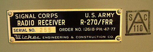
One note,...the serial number on the military tag of all BC Super-Pro receivers will not match the Hammarlund factory serial number stamped on the rear of the chassis. The tag number was usually assigned for the Signal Corps by Hammarlund for that receiver to be part of a specific contract quantity. It will never match the chassis-stamped serial number that was issued at the time of assembly.

The following tables are rough estimates based on serial numbers encountered weighed against quantity of receivers seen and the assumed division of the serial number pool.

Serial Number Sequence with Estimated Production

           Model                     Serial Numbers            Quantity Built

   SP-10 Series....................1 up to ~1000........actual receivers ~500

   SP-100 Series..................1000 to ~4000.......actual receivers ~1200 (SNs shared with HQ-120X) 

   SP-200 Series (pre-war)...4000 to ~10000.....actual receivers ~1800 (SNs shared with HQ-120X)

   SP-200 Military..............~10000 to 30000+....actual receivers ~ 10000+

   SP-400 Series.................... 4-0001 up to?....actual receivers ?


Year to Serial Number Table

         SN Range        Year           Models

         1 to 1000 ........... 1936.......SP-10, PS

         1000 to 3000.......1937.......SP-100, PS

         3000 to 3800.......1938.......SP-100, PS, HQ-120X

         3800 to 5000.......1939.......SP-100, SP-200, PS, HQ-120X

        5000 to 8500........1940.......SP-200, PS, HQ-120X

        8500 to 10000......1941.......SP-200, PS, HQ-120X

      10000 to 14500......1942.......SP-200, BC series, PS, HQ-120X (RBG uses a different format of SNs)

      14500 to 19000......1943.......SP-200, BC series, PS

      19000 to 25500......1944.......SP-200, BC series, PS

      25500 to 30000+....1945.......SP-200, BC series, PS

Known Serial Number Log

This is a log of known and reported serial numbers for all Hammarlund Super Pro receiver types made prior to the SP-600 receiver (Super-Pros from 1936 to 1948.) Also included are the SP power supplies with "matched-pair" indicators where known. I've also included the HQ-120X since it was serialized from the same number sequence as the Super-Pro and those serial numbers do affect the total production quantity of appropriate Super-Pro receivers. I've also included the military RBH/CHC-46140 out of curiosity. The Comet Pro receivers are included to show they were serialized from a different sequence of numbers.

The Super Pros are broken down into the various civilian models and the three Signal Corps military versions. Likewise, the power supplies are divided into civilian and military. Be sure to observe that the Signal Corps tag on the front of the SP receiver has a Signal Corps serial number and the receiver itself has a Hammarlund assigned serial number stamped on the rear apron of the chassis. The Hammarlund assigned serial 
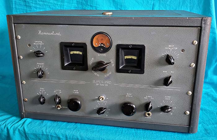
number is what we are logging. Note that the SP-400 serial numbers are using a different format with one digit, a hyphen followed by four digits.

SP-10:  576, 674(ps 804), 720(ps 721), 979(ps 987), 1023, 1110,

SP-100: 1352*, 2562(ps 2612), 2564(ps 2615), 2570, 2672(SX), 2714, 2730(LX), 2746(ps 2785), 3356,
3387(ps 3388), 3417(ps 3400), 3665(LX-ps 3649), 3826, 4106(LX), 4475(LX),

SP-150: 3055(ps 3105),

SP-200X:  4121, 4227, 4239, 4833, 4912, 4955, 5580, 5658, 6005(ps 6056), 6045, 6239(ps 6215), 7060(SC), 7334, 7853, 8295, 9419, 10664, 14910(ps 15204), 16135,

SP-200SX: 4146, 4289, 5226, 6230, 6289(ps 6331), 9759, 15775(ps 14653)

SP-200LX: 6884, 6965, 7353, 7381, 7545, 8023, 8423, 8466, 9262

SP-200X - Special: - 5733, 5858,

BC-779 (incl. Howard:) 6530H, 6873H, 7416H, 9030H, 9828, 11162H, 12421, 23688, 25298

BC-794: 19828,

BC-1004: 18320, 21009, 27942(ASP-1004),

R-129/U:

Super-Pro PS CIV: 3545(100), 4215B (200), 4287, 5164, 7036(200SC), 9238(200), 11184, 11865

Super-Pro PS MIL: 5514H (ASP-84), 9686(ASP-84), 17656(RA-94), 17783(RA-94), 21186(794), 22093(1004), 26595(RA-74), 28870(ASP-84)
 

HQ-120X: 7007, 7244, 7408, 7711, 9630, 9881,

RBG/CHC-46140: 519(RBG-2), 524(RBG-2), 982(RBG-2), 1473(RBG-2),


SP-400-X: 4-2683(ps 4-2200),

SP-400-SX: 4-1249(ps 4-1038), 4X2566,


Comet All Wave:  1006

Comet Pro:  7531, 7822, 8001, 8079

 NOTE: Sequential or close (matched-with receiver) serial numbered power supplies are listed in () along with receiver SN
                    
* = variation of standard model SP-10 or SP-100 (SP-200 listed as Special)
                                              
(Howard) = BC-779 receivers built by Howard Radio Co. as a contractor during WWII will have "H" suffix in serial number (Howard also built BC-1004 receivers)
(Special) = SP-200 Receiver with special frequency coverage or other non-standard features
(SC) = Signal Corps - military contract model                                        


Super-Pro Serial Numbers Needed

Since it appears that all Super-Pro receivers and their power supplies along with the HQ-120X receivers were serialized from a common serial number roster, any serial number from any of these Hammarlund products provides important information as to production quantity and date lines. Even the earlier Comet Pro serial numbers should show that it used a different set of numbers. If you have one or more pre-war Super-Pro receivers, SP power supplies, HQ-120X, RBG, SP-400 or Comet Pro receivers, please e-mail the serial number and what model it goes with to Western Historic Radio Museum. I'm just starting to log serial numbers (Aug2019) for the SP-400 receivers. The SP-400 serial numbers use a different format but as more SNs are logged it may show some connection to the earlier model serial numbers. Be sure if your Super Pro is a military version to send the Hammarlund serial number stamped on the rear of the chassis not the serial number on the ID tag. We will add the information to the Known Serial Number Log. With each number, more knowledge is gained about these incredible receivers and that information will be added to this website. Hopefully the result will be an on-line accurate source of information about the pre-war Super-Pro receivers.

e-mail Super-Pro info to: 

 WHRM-SUPER-PRO SERIAL NUMBERS


CONTINUE TO PART 2


Pre-War Super Pro Part 3                             Return to Home Index


Radio Boulevard
Western Historic Radio Museum

 Vintage Radio Communication Equipment Rebuilding & Restoration Articles,

 Vintage Radio History and WHRM Radio Photo Galleries

1909 - 1969

- 60 years of Radio Technology -


This website created and maintained by: Henry Rogers - Radio Boulevard, Western Historic Radio Museum © 1997/2023