|
1935 - SPA (SP-10) - June 29, 1935 Order Number
10932-NY-35 issued for Hammarlund SPA Super-Pro Receiver for the Signal
Corps US Army. SPA is identical
to the SP-10 except for the
installation of a data plate on the front panel. It's likely that these
receivers were delivered before the official March 1936
introduction presented in QST
magazine that month.
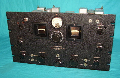
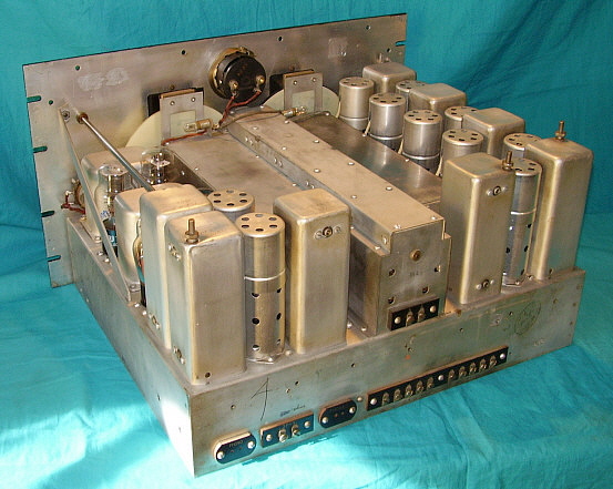
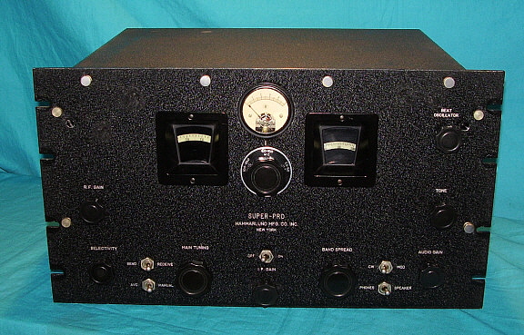
1936 - SP-10 - Uses all large-pin glass tubes,
has separate RF, IF and AF Gain controls along with Tone control, no
pointers on knobs
Variable coupling on Detector and AVC
transformers
Both audio transformers are potted units
Audio output transformer was probably an 8 ohm
Z output on all receivers
Resistors may have been added to create a 600 ohm output
Z on some receivers
Some receivers may have had a standard phone
jack audio output on front panel
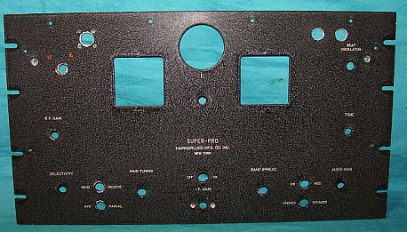
Aluminum front panel .187" thickness, engraved
nomenclature
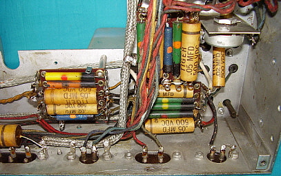
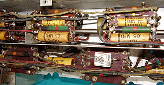
Paper-wax capacitors are usually Aerovox brand,
sometimes intermixed with Cornell-Dubilier brand
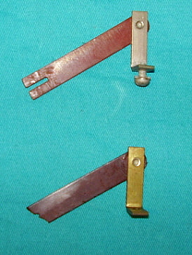
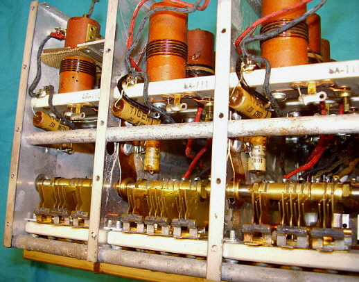
Spacing rods in RF tuning unit are
brass
Non-illuminated Tuning Meter measured total IF
amplifier current
S-version introduced in June 1936 tunes 1.2 to
40 MC
Bias series resistor string modified - 600 ohm
resistor replaced with 2-300 ohm, allowed moving detector input amp grid
connection
to junction which slightly increased bias
voltage
BFO Plate Load resistor changed from 5K to 50K
(may be parts list error as all known examples use 50K)
BFO Grid capacitor (100pf) changed from grid to
ground connection to parallel with grid leak resistor connection,
(possible schematic error)
Tone control eliminated in late production
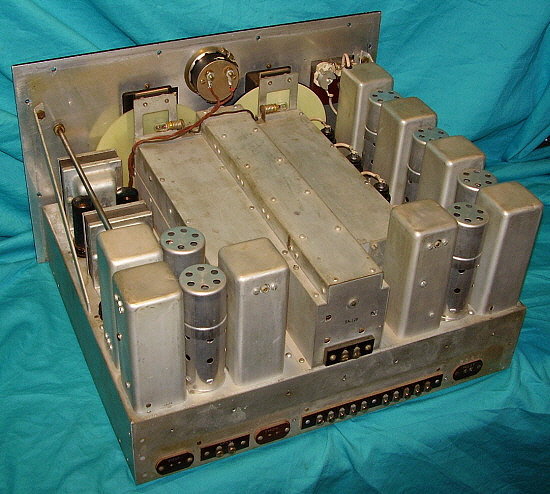
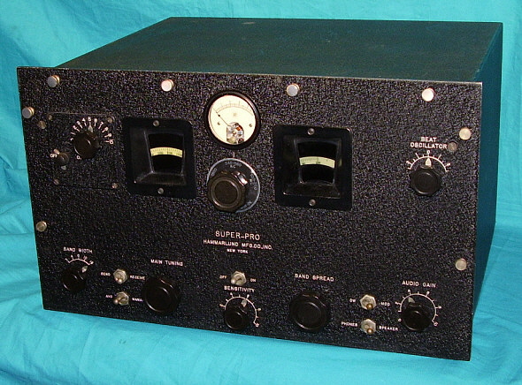
1937 - SP-100 - Introduced January 1937, uses eight metal octal
tubes and eight large-pin glass tubes, Sensitivity Control replaces
separate RF and IF gain controls,
Variable coupling AVC and Detector
transformers changed to fixed coupling, Selectivity control renamed Band
Width, engraved scales added to
Sensitivity, Beat Oscillator, Band Width and
Audio Gain controls
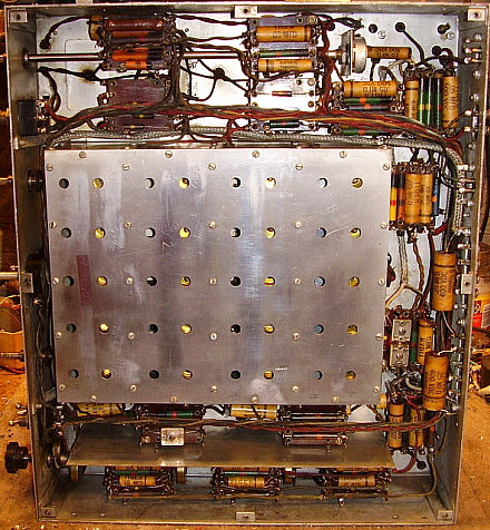
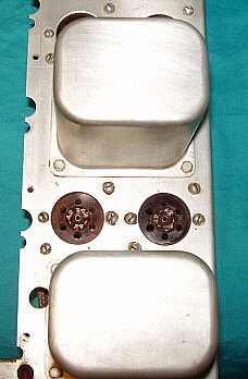
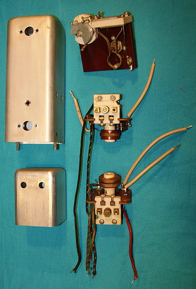
Fixed-coupled AVC and Detector transformers
allowed the component boards to be moved from under the chassis (SP-10)
to inside the transformer cans (SP-100)
New style small knobs with metal
pointers
Audio transformers changed from potted units
to vertical mount-frame types - output Z is 8 ohms
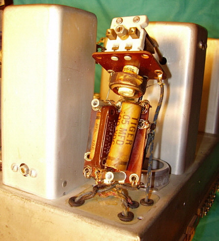
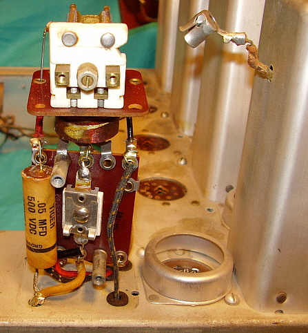
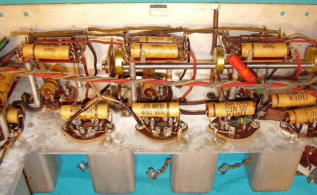
Paper-wax capacitors are usually
Cornell-Dubilier "TIGER" brand but could be intermixed with Aerovox
brand
Spacing rods in RF tuning unit are
steel
1938 - SP-100 - SP-100L introduced as low
frequency
version, 100KC-400KC and 2.5-20.0MC, production receivers have same
audio output configurations as the SP-100X.
Late
or Military versions of the "L" may have had front
panel "Phone" jack, dual secondary windings - 600Z speaker and Hi-Z
(8K) phones
"LX" version added a Crystal Filter
SP-150 console Super-Pro introduced in July
1938
1939 - SP-100 - SP-100 Crystal Filter - separate
smaller panel eliminated on last of series and CF mounted directly to
front panel
SP-200 introduced October 1939, added Noise
Limiter, Amplified AVC redesigned, Crystal Filter redesigned, IF section
redesigned
Illuminated S-meter replaced Tuning Meter
Over/under toggle switches replaced with
rotary switches with knobs, 18 tube circuit, larger power cable because
of
increased diameter of tube heater wires,
early SP-200 may use SP-100 frame type audio transformers
1940 - SP-200 - Front panel Speaker/Phones
switch changed to .25" phone jack, added dual secondary windings to
output transformer
allowed separate 600 ohm Z and Hi-Z ohm
earphone outputs on X and SX version. It is possible that LX version
already had this configuration.
Audio transformers now potted units.
1941 - SP-200 - Front Panel changed to .125"
thick steel with stamped engraving filled white, front panel paint
changed to semi-gloss black
Steel front panels are nickel-copper plated on
front side only as corrosion preventative
Spacers added to panel mountings because of
thickness difference
1942 - SP-200 - Probable beginning of Signal
Corps BC series - some receivers may have rubber stamped SC order
numbers indicating that it was purchased from civilian source.
Militarization of power supplies with heavy
duty parts
1943 - SP-200 - Painting of front panel changed
to red oxide primer coat with grayish paint, color of the panels is
highly variable with gray, blue-gray and green-gray commonly seen.
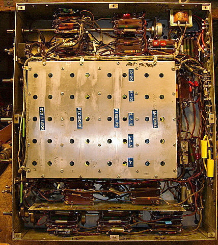
Tube layout charts are added to the top of the
RF box
Schematic added to inside of bottom cover of
the power supply
S-meter housing changed, full glass front
replaced with partial glass with zero adjust mounted in metal
TM-11-866 Signal Corps Manual, first version.
Manual covers BC-779, BC-794, BC-1004 and R-129/U plus power supplies
RA-74, RA-84 and RA-94
1944 - SP-200 - Probable year for contactor built
BC-779. Howard Radio seems to be the only company used as a contractor.
Howard also built BC-1004 receivers.
1945 - SP-200 - Late 1945 probable design
date for SP-400
Post -WWII - SP-400-X and
SP-400-SX models introduced in 1946. .54-30mc for X and 1.25-40mc for SX.
455kc IF for both versions, although "SX" version SN 4-1249 has a 465kc
IF. This suggests that perhaps
those receivers built early in production used WWII surplus Super-Pro
parts. When the 465kc IF parts exhausted, then the remaining SP-400s
were equipped with the new 455kc IF. Just speculation.
Other SP-400 changes are mostly cosmetic. No military contracts for
SP-400 receivers.
The Signal Corps continued to
support and use the SP-200 Super Pro receivers. Some of the MWOs and
manual additions date well into the 1950s.
Rectifiers changed in the RA-74D power
supply, 5U4 and 5Y3, also 12 cylindrical oil-filled paper capacitors
replace the two large block capacitors (1948)
Improvement Kit MC-531 shown in TM11-866 (Feb
1948 printing) - this is the three channel selectable crystal-controlled oscillator
upgrade
Wickes Engineering R-270/FRR receivers
supplied for AN/FRR-12 Dual Diversity Receivers - R-270 is a modified
BC-794 receiver (1948)
|