Radio Boulevard
Western Historic Radio Museum


Vintage Long Wave Receivers

Restoration and Performance Testing
Various Models of Vintage LW Receivers
featuring LW Receivers from 1923 up to 1961

in Four Parts

"Long Wave," or LW, is a commonly used term that generally refers to all of the EM spectrum below the AM-BC Band.
Proper terminology is Medium Wave, or MW, f range of 300kc to 3000kc, Low Frequency, or LF, f range of 30kc to 300kc
and Very Low Frequency, or VLF, f range of 10kc to 30kc

by: Henry Rogers WA7YBS


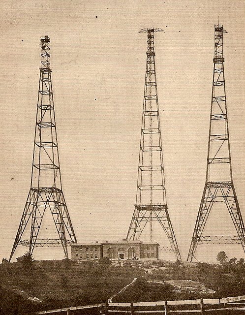
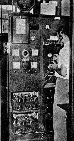
"The Three Sisters" Radio Towers and the NAA Station House at Arlington, VA   ca: 1920
The Navy wireless station at Arlington, Virginia was built in 1912, at the southwestern end of Ft. Myer, on land that was given to the Navy by the War Department. After the construction, the area became known as "Radio, Virginia" but the NAA location was also often referred to as "Ft. Myer" or "Arlington." The main tower was 600 ft tall (center in the photo) and two towers flanking the station house were 450 ft tall. The antenna was a triangular wire array suspended and tilted from the towers. The initial transmitter was a 100KW rotary spark type but it was soon joined by a more efficient 35KW arc transmitter. In Sept. 1915, NAA radio-communicated with the Mare Island Naval Shipyard in California becoming the first direct transcontinental two-way radio communication. Shortly after that, NAA exchanged a short message with Pearl Harbor becoming (at that time) the longest distance direct two-way radio communication at just under 5000 miles. In 1923, two additional towers were added (250' tall.) In the 1930s, the towers were painted orange due to an increase in airplane traffic and several "close-calls." Air traffic only increased and "The Three Sisters" were razed in 1941 due their hazardous location near the new and very busy Washington National Airport. Prior to the shutdown, all of the equipment and duties were moved to NSS (built in 1918,) the Navy station at Annapolis. In 1961, the call NAA was reassigned to the Navy VLF Submarine Communications station at Cutler, Maine.

Part 1 - Pre-WWII Receivers

1.  IP-501-A - RCA/Wireless Specialty Apparatus Co. - 1923 

2.  Type 105-A - Mackay Radio & Telegraph Co. - 1932

3.  RAA-3  -  USN-RCA Manufacturing Co., Inc.  - 1931 (1935 ver.)

4.  RAG-1 - USN-Hygrade Sylvania Corp. - 1933

5.  RIO  -  Dept. of Commerce-National Co., Inc.  -  1933

6.  Type R-100 - USCG-Federal Telegraph Co. - 1938

7.  SP-100LX Super-Pro - Hammarlund Mfg. Co., Inc. - 1938

8.  RAZ-1 & AR-8503 - USN-Radiomarine Corp. - 1937 (1941-42 ver.)

Part 3 - Post-WWII Receivers

16.  R-389/URR - Signal Corps-Collins Radio Co. - 1951

17. Type 3001-A - Mackay Radio & Telegraph Co.  - 1952

18.  SP-600VLF-31 - Hammarlund Mfg. Co., Inc.- 1955

19.  RA-17C-12 & RA-237-B - RACAL Engineering Ltd. - 1961

20.  Model 850/2 - EDDYSTONE-Stratton & Co. Ltd. - 1961
 

Using Selective Level Meters as Longwave Receivers, Other Receivers with LW Coverage, Regen Receivers vs. Superhets on LW, The Ultimate Vintage Longwave Receiver


Part 2 - WWII Receivers

9.   RC-123 - USCG-Mackay Radio & Telegraph Co. - 1942

10.  RAK-7, CND-46155 - USN-RCA-Andrea Radio Co. - 1944

11.  BC-344-D - Signal Corps-Farnsworth Radio & Telev. Corp. - 1944

12.  CR-91 (Camden AR-88LF) - RCA-Victor Div. of RCA - 1944

13.  RBL-5, CNA-46161-B - USN-National Co., Inc. - 1944

14.  AR-8510 - Radiomarine Corp. - 1944

15.  RBA-1 (CFT-46154) & RBA-6 (CFT-46300) USN-RCA-Federal Telephone & Radio Corp. - 1941-45
 

Part 4 - What to Listen to on LW

NDBs, LW-BC Stations, PE Time Signals

SAQ 17.2kc Alexanderson Alternator

USN VLF MSK Stations, Russian VLF "Alpha" Stations

Loop Antennas, Long Wire Antennas

Operating Vintage Gear on the 630M (472-9 khz) Log incl'd

USCG  Loran C Master Station"M"- Fallon, Nevada - 2007 Photo Tour

NBD Stations in Nevada  &  NDB Station Log


Vintage Long Wave Receivers - Part 1 - Pre-WWII

1.

 Wireless Specialty Apparatus/RCA
(later versions by Radiomarine Corp.)


IP-501-A - MW & LF Regenerative Detector Receiver-Amplifier

Commercial Shipboard Receiver from 1923

40kc  to  1000kc

(includes NDB reception log)

"Listening on longwave with a 1923, battery operated, regenerative receiver? You gotta be kidding!"

One has to remember that the IP-501-A was the commercial shipboard receiver. It was built to the highest standards of the day. It was well-known for its superior performance and reliability. It is the "R-390" of the 1920s.

Brief History - The initial versions of this receiver were built at Wireless Specialty Apparatus, a company that was owned by United Fruit Company. UFC was a member of the cross-licensing "Radio Group" headed by General Electric and included Westinghouse, AT&T, RCA and the United Fruit Company. WSA, through its original founder, Greenleaf Pickard, owned all of the crystal detector patents at the time (John Firth was also an original founder of WSA.)

At the end of WWI, Louis Hazeltine had designed for the Navy a superior vacuum tube, regenerative detector receiver that could operate in virtual presence of spark and arc transmitters. The much needed selectivity was due to a tuned antenna stage that was variably coupled to the detector and provided the selectivity needed and the ability to control just how much signal went to the detector. This allowed the regenerative detector to operate a maximum sensitivity without being over-loaded. The first contracts were in 1919 for the SE-1420 receivers (the forerunner to the IP-501 and IP-501-A) and WSA was one of the contractors. There were also subsequent contracts for the SE-1420 and its many variants over the next several years. When built for the Army, the SE-1420 was designated as the BC-131.

WSA built a few broadcast radios for RCA in 1921 and 1922 but by 1923 they had become part of RCA. For the next few years, RCA continued to have the shipboard radio business of WSA operate using the WSA plant and using WSA components to build shipboard equipment. By this time, all of the SE-1420 military contracts had gone to AMRAD and to NESCO but RCA/WSA continued to supply commercial shipping with their version designated as the IP-501 and additionally supplied the larger IP-501-A that combined the tuner-detector with the audio amplifers in one cabinet.

In 1927, RCA combined WSA with Independent Wireless Company and that organization became Radiomarine Corporation of America, a division of RCA. Radiomarine continued to build the IP-501-A up into the early thirties. Manuals for the IP-501-A were available from RMCA into the late-thirties. Removal of the IP-501-A from shipboard use probably started just prior to WWII since the receiver's regenerative detector easily coupled to the antenna and radiated the oscillating detector quite well. Ships often could pick-up an oscillating IP-501-A as far as five miles away (at sea.)

Circuit Details - This three tube receiver uses a three-circuit tuner with a regenerative detector and two transformer coupled audio frequency amplifier stages - not exactly unheard of for a lot of radio receivers in 1923. What really sets the IP-501-A apart from the other three-circuit tuner regen sets is its incredible Antenna Tuner section that is entirely shielded from the main part of the receiver (which is also entirely shielded.) The Antenna Tuner allows exact tuning of the antenna's impedance so the load remains the same on the Secondary circuit. It's like having a built-in pre-selector. The only transference of signal happens by way of the small variable coupling coil located inside the Antenna coil. The fact that the receiver cabinet and front panel are entirely shielded results in no hand-capacity effects when the receiver is operated as an autodyne detector. This makes tuning CW super-easy. The Secondary Tuner has six frequency ranges from 1000kc down to 40kc and the dial is calibrated in meters. The Tickler coil is actually a variometer built into the Secondary coil form and includes load windings from the Secondary inductance to improve regeneration on the lower frequencies. The audio amplifier section is standard and uses two RCA interstage transformers. The audio gain is more-or-less controlled by the filament voltage and the operator can also select how much gain is required by using one of the phone jack outputs. The phone jacks also control the filament voltage to the tubes and only the tubes needed are in operation when that jack is selected. Maximum audio is from the AF2 jack which provides Det + 2 AF stages. In high noise level conditions or for very loud signals, AF1 saves the operator's ears by using just one audio amplifier. If the DET jack is used, only the detector tube is in operation - this would be for receiving local transmissions. Intended audio output is to Hi-Z earphones but the IP-501-A will drive a horn speaker loudly from the AF2 jack. To power the receiver up requires 6vdc at .75A for the filaments, 45vdc and 90vdc for the B+ requirements and -4.5 for C bias. The filament adjustment pot controls the A battery into the receiver and is used to turn off the receiver. Pulling the phone plug from one of the jacks will turn off the tubes but the meter will still show A battery voltage unless the filament pot is turned off. The tubes normally used in the IP-501-A were UX/UV-201A triodes. Operating any radio receiver that uses batteries for its power source can be a hassle and expensive unless you are all ready set-up to run battery receivers. Usually highly-filtered power supplies provide "close to pure" DC voltages to operate these types of receivers. I use a Lambda 6vdc 4A power supply for the A supply, a 1920s RCA Rectron B Eliminator for the B supply and a 4.5vdc battery for the C bias. Hi-Z earphones are necessary for the audio output and I generally us a set of 2200 ohms dc, Western Electric 518W 'phones. The IP-501-A also requires a fairly large antenna worked against a true earth ground for best performance.


photo above: Inside the IP-501-A receiver showing the high quality construction

 In operation, the filaments are set to about 4.5 to 5.0vdc using the panel meter as reference. Tuning is accomplished with the Secondary Condenser and then "peaking" the signal with the Antenna Condenser. Sensitivity is controlled by use of the Tickler. Since an adjustable resonance and load can be controlled by the Antenna Condenser control, the Tickler control can be set to one position and doesn't require too much adjustment per each tuning range. Selectivity is controlled by the Coupling control. Changing the settings of any of the controls will always cause an interaction in any regen set when it is used as an Autodyne Detector (oscillating regenerative detector.) When the IP-501-A is used as a three-circuit tuner with Autodyne Detector, the Coupling control must be set to "Critical Coupling" for best performance. This requires the operator to tune through the Antenna Condenser's resonance while listening for a "double-click" (and for the oscillating to stop.) If the clicks are heard, this indicates too much coupling. Continue to loosen the coupling and retune the Antenna Condenser until no clicks are heard at resonance. Now the Coupling is set properly. Large changes in tuned frequency will require minor adjustments to the Coupling setting. All tuning can usually be accomplished using just the Secondary Condenser control for tuning stations and then using the Antenna Condenser for adjusting the signal to maximum. Now and again you will have to slightly re-adjust the Tickler. For tuning in NDBs, the IP-501-A should be operated as an Autodyne Detector receiver. This provides a heterodyne so the NDB carrier can be easily heard. Regenerative detectors can become unstable at the oscillation point and good construction helps to stabilize the regeneration. The IP-501-A is very stable and easy to operate in the Autodyne set-up since that was one of its intended uses - to copy the CW from arc transmitters.

Restorations -  I've had this IP-501-A since 1979. A ham friend (W7IND) sold it to me after he had traded a telephone pole for it. I have performed three restorations on the set over the years. The last one in 1984 brought the IP-501A back to full original configuration and appearance internally and very good restored condition externally. I used the receiver back in the 1980s with a 125' EFW antenna and tuned in all the normal AM BC stations one would expect. As far as Airport Non-Directional Beacons (NDB,) the only one I remember tuning in was SPK 251kc, located at the old Reno-Cannon AP. I remember SPK because they used to transmit voice weather with the MCW ID "SPK" in the background. I really didn't know how to get a lot of performance out of the IP-501-A back then. The AM BC performance was fine but listening to AM BC over a horn speaker gets boring after awhile. When I opened the museum in 1994, the IP-501-A was installed in a display case and it stayed in the case for almost 15 years. Around 2009, I had been thinking about trying something different, as a challenge to the performance capabilities of early regenerative receivers. Since the IP-501-A was the commercial receiver of choice in difficult environments and it had every indication of being the "best" of its day, I decided to give it a try. I used my ham antenna, a 135' tuned dipole, but with the feedline shorted. This would provide a vertical with large capacity hat configuration similar to the large "T" antennas of the twenties. Our initial tests turned up a small problem with the IP-501-A's circuit selector switch. We had no detector plate voltage but it was just a bad contact that needed a bit of cleaning and we were up and operating,...sort of. Lack of audio output was another easy fix. The bias SS power supply had failed and was at -25vdc, definitely in the cut-off region for UX-201As! I sub'd a battery for the bias and then the IP-501-A sprang to life. Before power-up, I had tuned the receiver to around 800 meters as a pre-set and, to my complete surprise, SX 367kc in Cranbrook, BC, Canada was coming in (this was at about 5PM local time in December.) I tuned in a few more NDBs and then decided to wait until about 10PM and try again. At 10PM, I received around 25 more NDBs tuning from 326kc up to 414kc. Best DX was the 2KW transatlantic beacon DDP 391kc in San Juan, Puerto Rico. 

IP-501-A NDB Log - 2009 - The following is the log of the NDBs copied using just the IP-501-A receiver and the 135' tuned dipole antenna with the feedline shorted. NDB location, frequency and power (if known) are listed. Total was 103 NDBs copied in a three-week period in January 2009.

To attain this level of performance from a 1923 regenerative detector receiver requires an excellent location,...well, Virginia City wasn't the greatest location but my QTH there was in a "null" area within the local QRN. Most of Virginia City is so RFI noisy that any AM reception is impossible. But,...a good location is necessary. A decent antenna also helps. The time of the LW season being in January is the proper time for just about the best DX conditions. Finally, unless the IP-501-A is setup for "Critical Coupling," virtually no NDBs will be heard. "Critical Coupling" will allow the most sensitivity and the ability to hear the weakest stations. It is essential to setup the IP-501-A in this manner to receive DX NDBs. And, of course, earphones are a "must" for hearing the really weak stations. I used a set of Western Electric 509W 'phones.

AA - 365kc - Fargo, ND - 100W
AEC - 209kc - Base Camp, NV
AOP - 290kc - Rock Springs, WY
AP - 260kc - Denver, CO - 100W
AZC - 403kc - Colorado City, AZ
BKU - 344kc - Baker, MT - 80W
BO- 359kc - Bosie, ID - 400W
CII - 269kc - Choteau, MT - 50W
CNP - 383kc - Chappell, NE - 25W
CSB - 389kc - Cambridge, NE - 25W*
CVP - 335kc - St. Helena, MT - 150W
DC - 326kc - Princeton, BC, CAN
DDP - 391kc - San Juan, Puerto Rico - 2KW
DPG - 284kc - Dugway Proving Gnds, UT
DQ - 394kc - Dawson Creek, BC, CAN
EUR - 392kc - Eureka, MT - 100W
EX - 374kc - Kelowna, BC, CAN
FCH - 344kc - Fresno, CA - 400W
FN - 400kc - Ft. Collins, CO
FO - 250kc - Flin Flon, MB, CAN
GLS - 206kc - Galveston, TX - 2KW
GUY - 275kc - Guymon, OK - 25W
GW - 371kc - Kuujjuarapik, QC, CAN
HQG - 365kc - Hugoton, KS - 25W
IOM - 363kc - McCall, ID - 25W
ITU - 371kc - Great Falls, MT - 100W
IY - 417kc - Charles City, IA - 25W
JW - 388kc - Pigeon Lake, AB, CAN
LBH - 332kc - Portland, OR - 150W
LFA - 347kc - Klamath Falls, OR
LV - 374kc - Livermore, CA - 25W
LW - 257kc - Kelowna, BC, CAN
LYI - 414kc - Libby, MT - 25W
MA - 326kc - Midland, TX - 400W
MEF - 373kc - Medford, OR
MF - 373kc - Rogue Valley, OR
MKR - 339kc - Glascow, MT - 50W
MLK - 272kc - Malta, MT - 25W
MO - 367kc - Modesto, CA - 25W 
MOG - 404kc - Montegue, CA - 150W
MR - 385kc - Monterey, CA
NO - 351kc - Reno, NV - 25W
NY - 350kc - Enderby, BC, CAN
ON - 356kc - Okanagan, Penticton, BC, CAN*
OT - 378kc - Bend, OR
PBT - 338kc - Red Bluff, CA - 400W
PI - 383kc - Tyhee, ID
PN - 360kc - Port Menier, Anticosti Is., QC, CAN*
PTT - 356kc - Pratt, KS - 25W*
QD - 284kc - The Pas, MB, CAN
QQ - 400kc - Comox, BC, CAN
QT - 332kc - Thunder Bay, ON, CAN
RD - 411kc - Redmond, OR - 400W
RPB - 414kc - Belleville, KS
RPX - 362kc - Roundup, MT - 25W
RYN - 338kc - Tucson, AZ - 400W
SAA - 266kc - Saratoga, WY - 25W
SB - 397kc - San Bernardino, CA - 25W
SBX - 347kc - Shelby, MT - 25W
SIR - 368kc - Sinclair, WY
SX - 367kc - Cranbrook, BC, CAN
SYF - 386kc - St. Francis, KS - 25W
TAD - 329kc - Trinidad, CO
TV - 299kc - Turner Valley, AB, CAN
TVY - 371kc - Tooele, UT - 25W
ULS - 395kc - Ulysses, KS - 25W
VQ - 400kc - Alamosa, CO
VR - 266kc - Vancouver, BC, CAN
WG - 248kc - Winnepeg, MN, CAN
WL - 385kc - Williams Lake, BC, CAN
XD - 266kc - Edmonton, AB, CAN
XH - 332kc - Medicine Hat, AB, CAN
XS - 272kc - Prince George, BC, CAN
XX - 344kc - Abbotsford, BC, CAN
YAZ - 359kc - Tofino, Vancouver Is., BC, CAN
YBE - 379kc - Uranium City, SK, CAN
YCD - 251kc - Nanaimo, BC, CAN
YHD - 413kc - Dryden, ON, CAN
YJQ - 325kc - Bella Bella, BC, CAN
YK - 269kc - Castlegar, BC, CAN
YKQ - 351kc - Waskaganish, QC, CAN*
YL - 395kc - Lynn Lake, MN, CAN
YLB - 272kc - Lac La Biche, AB, CAN
YLD - 335kc - Chapleau, ON, CAN
YLJ - 405kc - Meadow Lake, SK, CAN
YMW - 366kc - Maniwaki, QC, CAN*
YPH - 396kc - Inukjauk, QC, CAN
YPL - 382kc - Pickle Lake, ON, CAN
YPO - 401kc - Peawanuck, ON, CAN
YPW - 382kc - Powell River, BC, CAN
YQZ - 359kc - Quesnel, BC, CAN
YTL - 328kc - Big Trout Lake, ON, CAN
YWB - 389kc - West Bank, BC, CAN
YWP - 355kc - Webequie, ON, CAN
YY - 340kc - Mont Joli, QC, CAN
YYF - 290kc - Penticton, BC, CAN
YZH - 343kc - Slave Lake, AB, CAN
ZP - 368kc - Sandspit, QC IS., BC, CAN
ZSJ - 258kc - Sandy Lake, ON, CAN
ZSS - 397kc  Yellowhead/Saskatoon, SK, CAN
ZU - 338kc - Whitecourt, BC, CAN
Z7 - 408kc - Claresholm, AB, CAN
3Z - 388kc - Taber, AL, CAN*

* = Newly NDB heard

2022 NOTE: A lot of these NDBs have been decommissioned over the past 11 years. At least 40% of those logged are no longer transmitting. Today it would be very difficult to tune in this many NDBs in this length of time on almost any LW receiver due to the greatly reduced number of stations still operating.


2.

Mackay Radio & Telegraph Company


Radio Receiver Type 105-A    

Serial No. 32081

Commercial Shipboard MW, LF & VLF
Regenerative Detector Receiver from 1932

16kc  to  1500kc


built by: Federal Telegraph Company


photo right: Sepia photo print from original Mackay brochure

Mackay Radio & Telegraph Company was founded by Clarence Mackay, son of John W. Mackay, one of the "Big Four of the Comstock" fame in Virginia City, Nevada. John Mackay initially made his fortune in Comstock silver but he later (1883) moved into telegraphic communications. Mackay, along with publisher J. Gordon Bennett Jr., formed several telegraph communications companies to compete with Jay Gould's Western Union. Postal Telegraph Company (1886) was the best known, along with Commercial Cable Company (1884). Eventually, these companies, along with other Mackay-Bennett telegraph companies, had transoceanic cables across both major oceans. When John Mackay died in 1902, Clarence inherited the businesses. Clarence Mackay saw to the completion of the transpacific cable in 1904. Radio was added to the business end of things in 1925 to provide "radiogram" service to every area of the world. Mackay Radio was mainly interested in maritime communications which went along with the maritime radio-telegraph business. By 1928, ITT had merged with most of Mackay's business interests but Clarence Mackay, who was a well-liked and respected CEO, remained president of Mackay Radio until his death in the late-thirties. The Mackay-ITT name continued on and nowadays Mackay Communications is located in North Carolina.

Federal Telegraph Company started out in Palo Alto, California mainly dealing in arc transmitters. At one time, Lee DeForest worked for the company but Frederick Kolster was the chief engineer for most of FTC's history. FTC bought Brandes and created a new division of FTC called Kolster Radio Company specifically for selling consumer radios in the mid-twenties. FTC became involved with Mackay Radio in 1926 when Mackay bought a radio station that had belonged to FTC. When Mackay sold his interests to ITT, Federal Telegraph Company continued to do most of the Mackay Radio work under contract to ITT. Federal Telegraph moved to New Jersey in 1931 after it was purchased by ITT. For awhile ITT tried the consumer radio market with Kolster International but it was a short-lived venture. The name of Federal Telegraph Co. was changed to Federal Telephone and Radio Company in the early 1940s.


photo left: One of the Federal Telegraph Company buildings in California about 1927

The Type 105-A is a pre-WWII commercial shipboard receiver that dates from after the Federal Telegraph move to New Jersey since the ID tag lists Newark, N.J. as FTC's location. Later Mackay radios incorporate the year of manufacture into the first two digits of the serial number. It looks like this is also the case with the Type 105-A and, with the serial number 32081, this receiver was built in 1932. The circuit uses four tubes that were originally four-pin triode tubes with direct-heated filaments. Either 201-A tubes (4.5vdc to 5.0vdc filament voltage) or type 30 tubes (2vdc filament voltage) are specified in the Mackay 105-A brochure. However, this receiver was modified in the distant past to use five-pin cathode-type triode tubes. To be compatible with the typical DC voltages available aboard ship type, six volt filament tubes were probably installed. Type 76 tubes would be the logical choice. The frequency coverage is 1500kc down to 16kc in seven tuning ranges. Power was supplied by batteries. Like earlier designs for shipboard receivers, the Mackay 105-A utilizes an LC Antenna tuner ahead of the regenerative detector to increase gain and selectivity. An Antenna Series Condenser switch selects various value capacitors to match the ship antenna to the receiver input and a stepped Tone control provides some relief from static. The panel meter is a dual meter that normally reads filament voltage but B+ voltage can also be monitored by activating a panel switch. The left large tuning knob tunes the Antenna Condenser, the middle large knob controls the Regeneration Condenser and the right large knob tunes the Detector Condenser.

The Mackay 105-A is built for shipboard use being physically stout and very heavy. The chassis, the front panel, the cabinet (if I had one) and most of the shield panels are made from cadmium-plated brass. The cabinet and panel was painted Mackay Gray. Originally, sn: 32081 could have been in a metal cabinet (as shown in the sepia photo above) but the Mackay brochure also indicates that the receiver could be supplied without the cabinet for panel mounting, possibly in one of the Mackay Marine Radio Units that would have housed the majority of the radio gear for the ship. The installation shown below (S.S. Manhattan) shows the various Mackay equipment mounted in their individual cabinets. It's also possible that when the receiver was rebuilt to use five-pin tubes the cabinet was discarded then to allow for panel mounting.


photo right
: Mackay Type 105-A sn: 32081


photo above:
This is the radio room onboard the S.S. Manhattan, ca. 1938, entirely equipped with Mackay Radio and Telegraph Company gear. The Type 105-A receivers are flanking the central transmitter in the photo. The receiver to the right of the "right-side" Type-105-A is a shortwave receiver, the Type 104-B. This photo is from the frontispiece of Sterling's THE RADIO MANUAL, 3rd Edition, 1938.


photo above: The chassis of the Mackay 105-A. The rectangular box on the right side of the chassis contains the power input filters. The right side cylinder contains the RF choke while the remaining cylinders contain the AF interstage coupling transformers. The chassis is cadmium-plated brass.


photo right: The underside of the Mackay 105-A. The lower coils are the LF coils and the upper coils are the MW coils. 

This Type 105-A was an eBay find that was purchased in October 2009. The receiver has vintage modifications that were probably installed during its life as a "shipboard receiver." The original concept appears to have been designed for exclusive DC operation. The Filament control has been bypassed since cathode tubes were now being used and since cathode type tubes are used, AC could be supplied to the tube heaters. However, AC voltage won't read on the panel meter since it doesn't have an internal rectifier - also the internal series resistor is burnt out for the B+ section of the meter. Additionally, there was a DC voltage input filter on the filament line that has been bypassed. I have examined this Type 105-A carefully and the five pin tube sockets are not original but the rework looks very professional and of excellent quality. Many decades ago, there were several small marine radio equipment companies that were usually located near shipyards that specialized in repair, rebuilding or upgrading and selling used shipboard radio equipment. Most likely, this Type 105-A was modified by such a business. The good news is that this Type 105-A is a working receiver. It operates very much like the IP-501-A in that the position of the regeneration control is dependent on how you set-up the Antenna Tuning. Though there is no coupling control, the interaction between the Antenna Tuning and Regeneration does about the same thing as setting the "Critical Coupling" on the earlier IP-501-A. The Antenna Series Condenser switch compensates for use of a single antenna length and adds to the range of the Antenna Tuning. The Tone Control knocks down the static noise on the LF and VLF ranges. It seemed likely that 6 volt triodes, like the Type 76, would have been used since six volt battery power would have been commonly found on commercial ships. At first, I used an old Signal Corps power supply that provides 6.3vac and regulated 135vdc to power up the Type 105-A. Using the 135' Tuned Dipole antenna with the feed line shorted at the receiver antenna terminal, I was able to easily receive all of the usual longwave signals using WE 509W 'phones for the audio output. Some of the NDBs tuned in were MM 388kc from Fort McMurray, Alberta, ZP 368kc Sandspit, BC for best DX but also consider SYF 386kc, a 25W beacon in St. Francis, KS. The VLF reception included the Navy MSK stations in Jim Creek, WA (24.8kc) and Cutler Maine (24.0kc.)

Update on Mackay Type 105-A Performance: The high noise level of the Type 105-A seemed to be limiting the reception of very weak signals. I finally decided to run the heaters on DC voltage which was a subtle change and hardly noticeable but very weak signal detection was improved. I was able to receive WG 248kc in Winnepeg, MB and RL 218kc in Red Lake, ON. Note that both of these NDBs are in the 200kc - 250kc part of the spectrum - a particularly noisy area. DC voltage on heaters does help on weak signal detection. 

Additional Note on Set-up and Performance: I decided to try an entirely different DC power supply set up using a 6vdc 4A Lambda power supply for the tube heaters and a vintage B eliminator, the RCA Duo- Rectron, to test if the noise would be further reduced. The change was amazing! Apparently the old Signal Corps power supply wasn't filtered very well or I was exceeding it's load capabilities, after all, it was for running a BC-221. The Duo-Rectron in combination with the 4A Lambda works great because now the MCW signals from NDBs have no distortion and the tone sounds like a good sine wave. Luckily, there happened to be a true CW station operating on 425kc during my test. This was probably an "events" type of operation of one of the old Point Reyes stations since the signal was very strong and was only "on the air" for about one hour. This CW also was very pure in tone. The operation and performance of the Mackay Type 105-A only seems to improve that closer one gets to operating it on pure DC (as original.) November 21, 2009


3.

RCA Manufacturing Co., Inc.


Navy Department
Bureau of Engineering

RAA-3
Serial No. 64

RF Tuner - CRV-46034-A
IF/AF Amplifier - CRV-50022-A
Power Unit - CRV-20016-A


MW, LF, VLF
Superheterodyne Receiver - 1931

10kc  to  1000kc

This is a teaser,...like a preview,...a way to let longwave enthusiasts know what's coming up pretty soon. I've been working on the 1935 RAA-3 since June 2017. I'm hoping to have the receiver operational someday but the electronic restoration work still necessary is formidable. However, the effort I've put forth on the mechanical and cosmetic restoration has changed the RAA-3 from a "corroding hulk" to an impressively enormous and beautiful Navy LW receiver. This 465 pound, over three feet wide, behemoth of a receiver has three sections,...the RF Tuner, the IF/AF Amplifier and the "not shown in the photo" Power Supply. The RAA was the first long wave superheterodyne built for the US Navy in 1931. This receiver is the RAA-3 from 1935. It has 14 tubes, 4 individual 2-stage IF amplifiers that are selected by the band switching and a lot more. This ultra-rare receiver was in absolutely horrible condition after having been stored outside for decades, wrapped-up in a tarp. However, it's electronic restoration is progressing and will be coming together in the near future. Go to "Navy Department - RCA RAA-3 Superheterodyne Long Wave Receiver" article that details the restoration process so far - use navigation Home Index at the bottom of this page.
 

4.

Hygrade Sylvania Corp.

Navy Department
Bureau of Engineering


RAG-1

Serial Number: 1

CHS-46042 - Receiver
CHS-20032 - Power Unit

1933


MW, LF & VLF

15kc to 600kc

TRF Receiver with Tracking BFO

(includes NDB reception log)

The Navy needed a less expensive alternative to the gargantuan RAA receiver. A receiver that would be easier to fit into a smaller ship's radio room. A receiver that was easier to maintain and more reliable. The result was the RAG-1 and RAH-1 combination of receivers that allowed frequencies from 15kc up to 23mc to be received. The RAG-1 was the low frequency receiver covering 15kc up to 600kc. There was only one contract for RAG-RAH receivers and it was from July 13, 1933. These receivers were used by the Navy from about 1934 up to around 1940. The RAG-RAH receivers were removed from ships before WWII because their lack of heavy-duty construction limited their reliability for wartime use at sea.

Circuit Description -  The RAG-1 Type CHS-46042 is an eight tube, TRF receiver that also employs a tracking BFO that is adjusted to always be 1kc higher than the receiver's tuned frequency. The tuning condenser is a "stacked" assembly with the lower five-gang air variable being the main tuning of the RF amplifier grid LC. The smaller upper five-gang tuning condenser adjusts the coupling between the RF plate on the stator and the next stage RF grid on the rotor. Since the RF amplifier grids can't be all connected together, the rotors are mounted on a Garolite shaft (a dense type of fiberglass.) The gang on both condensers that's closest to the front panel tunes the BFO as the main tuning is adjusted. The BFO is always operational since the RAG-1 is "primarily a CW receiver." The RAG-1 Sensitivity is controlled by varying the negative "grid bias" on the three RF amplifier tubes and that RF amplifier output is routed to a triode detector stage. The detector output is interstage transformer coupled to a tunable Bandpass audio filter, called "AUDIO TUNING" which allows the operator to adjust the resonant frequency of the filter thus "peaking" the desired CW frequency. There are two ranges selectable for 450hz to 750hz or from 750hz to 1300hz and a "wide band" position selected with the "OFF" position that removes the tunable audio filter from the circuit. The AUDIO TUNING adjustment mechanically varies the position a hinged section of the inductor's laminated iron core. The audio signal is then routed to a large Audio Bandpass Filter assembly that provides a narrowed bandwidth of 450hz to 1300hz with the center frequency optimized for CW at 800hz. The BP Filter output is interstage transformer coupled to the first audio amplifier and then the audio is RC coupled to the audio output. The audio line also has an adjustable bias-controlled AVC LEVEL control that acts like an output limiter to keep the receiver's audio output from over-driving the operator's ear with unexpected strong signals or static bursts. The AVC limiter tube is a full-wave rectifier that is on the audio line to chassis, acting something like a clipper limiter on the output of the first audio amplifier. The AVC can be switched OUT during quite reception conditions. The 600Z ohm audio output is available at the TEL jack on the front panel and is also routed out the power cable to connect to the Control Unit.   >>>

>>>  The tuning ranges are as follows:

Tuning Range 1 - 15kc to 38kc

Tuning Range 2 - 38kc to 95kc

Tuning Range 3 - 95kc to 240kc

Tuning Range 4 - 240kc to 600kc (actual top end is 650kc)

The tuning dials are a 0-100 lower dial and a 0-10 upper dial with ten revolutions of the 0-100 lower dial showing from 0 to 10 on the upper dial. Tubes used are (3) 6D6 - RF Amplifers, (1) 76 - Detector, (1) 6D6 - BFO, (1) 76 - 1st Audio Amplifier, (1) 41 - Audio Output Amplifier, (1) 84 - AVC Limiter, (1) 80 - PS Rectifier. Voltage required is 6.3vac for the tube heaters along with +180vdc for B+ and -55vdc bias voltage. The 80 rectifier required 5.0 vac which was supplied by the PS power transformer and the -55vdc bias voltage was probably obtained by connecting the center tap of the power transformer's HV winding to chassis through a wire wound resistor. This will result in a negative voltage present at the center tap that can be used for bias purposes. The 600Z audio output power is only 250mW implying that earphones were the intended reproducers to be used. As mentioned, the audio is also routed out the power cable at the back of the receiver for connection to the Control Unit CHS-23067 that allowed switched 'phone connections between the RAG-1 and its companion receiver, the RAH-1. Sensitivity is rated at an impressive 1uv to 4uv. Power Supply was identified as CHS-20032.
The OUTPUT meter measures the audio output level and has a scaling switch that allows changing the meter full scale or turning the meter off. The FILAMENT meter acts as an ON-OFF indicator and also measures the tube heater voltage. As mentioned, the RAG-1 BFO is always operational. The OSC. TEST switch allowed the radioman to disable the BFO by pressing the push-button. This shorted the feedback winding in the BFO coil to chassis and disabled the BFO. During quiet reception conditions or a lack of any signals to tune to the radioman may not be sure his RAG-1 was operating correctly. The OSC. TEST button was pushed and a resulting "click" was heard in the 'phones which confirmed that the RAG-1 was operating.

RAG-1 Accessory Components - In addition to the RAG-1 receiver, the complete setup included a Control Unit CHS-23067, AC Power Supply CHS-20032 and four interconnecting cables (one cable is permanently connected to the receiver as its power cable.) The Control Unit was a device that allowed the radioman to control the basic operation of both the RAG-1 and the companion receiver, the RAH-1. The Catalog of Navy Radio Equipment isn't detailed on how the Control Unit works just stating that with the two receivers a total frequency coverage from 15kc up to 23mc. Generally, this allowed one radioman to "guard" two frequencies simultaneously. This implies that one Control Unit was provided for operation of the pair, RAG-1 and RAH-1. The RAG-1 was connected to the Control Unit via its 8 foot long power cable. The RAH-1 also was connected to the same Control Unit via its 8 foot cable. Also, a 16 foot long cable connected the Control Unit to the AC Power Supply which was capable of powering both receivers. It's possible that there were two 16 foot interconnecting cables from the Control Unit to the AC Power Supply each with its own input connections (the Catalog of Navy Radio Equipment isn't specific about this but shows two 16 foot cables in the parts list.) The Control Unit would be able to "switch on" the AC Power Supply which in turn powered up either RAG-1 or the RAH-1 or both using switches on the Control Unit. The RAG-1 front panel ON-OFF switch was only functional if the receiver was to be operated on batteries in an emergency situation. This probably also applied to the RAH-1. Besides the basic "power on" function, it's likely that the Control Unit also provided audio outputs from each receiver that could probably be switched between the RAG-1 and the RAH-1 to a single set of 'phones using a switch. This would allow one radio operator to easily "guard" two pre-set frequencies by just switching back and forth between the two receiver's audio outputs. Normally, these types of Control Units would be on located on the radioman's table thus the shorter receiver power cable of 8 feet length. The AC power cord from the PS to the AC line was 18 feet 8 inches long.

Restoration - The RAG-1 was given to me by my old LW friend Dave Sampson. The idea was to restore the RAG-1, to document its circuit, its construction and its performance. Sometime in RAG-1 Serial Number 1's past it was dropped from probably a high storage shelf (at least six feet off of a concrete floor.) This severely damaged the front panel and chassis. The receiver required extensive mechanical repairs and restoration. Additionally, the physical damage also extended to several of the circuit components that then also needed rebuilding. The Audio Bandpass Filter unit had to be completely rebuilt. Besides three broken ceramic coil forms, the garolite shaft of the grid to plate tuned-coupling capacitor was also broken. Major disassembly was required to straighten all of the bent sheet metal including the front panel.  


photo above: Some of the physical damage. OUCH! The severe bend in the chassis virtually destroyed the Audio Bandpass Filter unit. The rear-most can is the coupling transformer on the output of the Audio Bandpass Filter. The really "crunched" can contains two VLF RF coils that were damaged (L1 and L2.)
  Electronically, the detector plate interstage coupling transformer had an open primary. Also, the circuitry had been slightly compromised by a minor modification and needed to be put back to original in order for the RAG-1 to function correctly. Compounding the restoration difficulty was the fact that absolutely no documentation exists for the RAG-1. No schematic, no manual, no photos,...nothing. The ONLY source of information is the somewhat brief description in the Navy Catalog of Radio Equipment (no photo in the Navy Catalog either.) Luckily, the Navy Catalog provides just enough information about the RAG-1 to allow circuit analysis using the existing wiring within the receiver chassis to conclude how the RAG-1 functioned, how to restore it and how to operate it. The RAG-1 SN: 1 restoration is covered in great detail with lots of "in process" photos in our web-article "USN RAG-1 LW Receiver" use the Home/Index to navigate.

Powering the RAG-1 - I use a HP 712B power supply since this one piece of equipment can provide all of the voltages required by the RAG-1. I had to build an extension for the RAG-1 power cable since it had been cut to just 12" in length. The extension cable used a seven pin Amphenol mating plug-socket and lengthened the power cable to five feet. The connections to the HP 712B are via the 5-way binding posts on its front panel. The voltages provided are 6.3vac at 10A capability (the RAG-1 only requires 2.5A,) +180vdc B+ is provided by the adjustable +HV supply (0 to +500vdc range) and the negative bias (-50vdc) is supplied by the adjustable 0 to -150vdc bias supply. Full voltage monitoring is easy with B+ and negative bias metered by the HP 712B and the 6.3vac monitored by the RAG-1 filament meter. B+ current has full-time monitoring on the HP 712B with the RAG-1 typically drawing 47mA while operating.

Alignment Equipment - There aren't very many RF Signal Generators that will provide a sine wave output down to 15kc. While a Function Generator can be used, I've found these typically don't have a very fine control of the frequency adjustment and many aren't very stable when in the higher kilocycle range (high for a function generator.) One piece of vintage equipment that's really ideal for LW alignments is the General Radio Type 1001-A RF Signal Generator. It's a late-1950s laboratory-type RF signal generator that's very stable, the frequency accuracy is very good, the attenuator is great and, best of all, it can provide a RF signal down to 5kc. The disadvantage is the GR-874 output connectors require General Radio "874 to BNC" adaptors but they are easily available and make connections to the Type 1001-A easy. 
 

photo left: Under the chassis of the RAG-1 after restoration. The bottom cover is removed showing the extensive shielding. Of note is the huge Audio Bandpass Filter which is now restored. It's built on its own chassis and is comprised of six large solenoid coils and associated capacitors.

Alignment - I aligned the RAG-1 like I would any TRF receiver. I set the dial for 9.50 which is very near the high end of each tuning range. The RF signal generator was coupled through a 400pf capacitor to the antenna input. The generator was tuned until the the signal was heard in the receiver. There are five adjustments per band. The ANT/1RF stage, the 2RF stage, 3RF stage, DET stage and the BFO stage. Once the RF signal generator is heard, then starting at the ANT/1RF stage that coil's trimmer is adjusted for peak response. This is repeated moving forward in the stages except for the BFO. The BFO requires the signal to be tuned exactly with the BFO disabled, press the TEST OSC switch to disable the BFO. Once the signal is exactly tuned, the TEST OSC button is released and the BFO trimmer is adjusted to approximately 1kc higher than the tuned frequency. Check that the BFO is higher by adjusting signal generator 1kc lower in frequency and the BFO note should "zero beat" if adjusted correctly.

As part of the alignment, I also created a "Tuned Frequency to Dial Readout Correlation Chart." This allows finding where in the spectrum the RAG-1 is tuned since its dial readout is 0.00 to 10.00 reading two dials, one that's 0 to 100 and the other being 0 to 10. One rotation of the 100 dial equals 1 increment on the tens dial. Creating the tuning chart showed two minor tuning discrepancies. On band 1, the high end of the tuning range is 35kc at 9.90 on the dial and 38kc can't be tuned (on Band 1, it can be tuned on Band 2.) This error is just about 10% which was probably within the original spec. On band 4, the high end of the tuning range extends to 650kc at 9.85, not 600kc, which may have been intentional in the design to give a slight extension to the high frequency coverage (it's still less than 10% off.) Otherwise, frequency coverage is just slightly extended above and below the ranges indicated on the front panel nomenclature.

Performance - There's no doubt that the Navy wanted a shipboard receiver that was easy to operate and while providing solid reception on all of the tuning ranges. All that's necessary to receive signals is to apply power, advance the SENSITIVITY until background noise is heard, peak the ANTENNA TRIMMER and then begin tuning in signals. If the noise level is high, the AUDIO TUNING can be used to enhance a specific heterodyne beat note, reducing noise and increasing selectivity. If there are static crashes, the AVC can be switched on and the AVC LEVEL adjusted to reduce the static peak level noise. The RAG-1 is a fine receiver that is easy to operate. Performance is especially good on VLF when using the AUDIO TUNING. Noise is greatly reduced and the increased selectivity allows separating the USN VLF MSK stations, even NML 25.2kc from NLK 24.8kc (only 0.4kc separation.) AUDIO TUNING also helps with WWVB and JJY, both transmitting pulse encoded signals. NDBs are easier to tune without the AUDIO TUNING on. With the BFO operating 1kc above the tuned signal, the NDB morse ID will be heard slightly "off zero" which actually makes the MCW signal seem stronger and easier to copy. Below is a log of some of the signals that the RAG-1 received during testing in late-May 2020.

RAG-1 Reception Test Results

The RAG-1 was powered by a HP 712B power supply providing 6.4vac tube heaters, +180vdc B+ and -55vdc bias. The antenna was a 275' "T" wire antenna. Reproducers were 600Z ohm earphones.

Daytime Test Reception
:

VLF

NML - 25.2kc -  LaMoure, ND - Very strong signal  -  6.39 on RAG dial
NLK - 24.8kc  - Jim Creek, WA - Extremely strong signal  -  6.18 on RAG dial
NAA - 24.0kc - Cutler, ME - Strong signal  -  5.88 on RAG dial
NPM - 21.4kc - Lualualei, HI - Very strong signal  -  4.68 on RAG dial
NWC - 19.8kc -  Exmouth, Australia - very weak signal  -  3.86 on RAG dial

All of these USN VLF MSK stations are very strong signals that are easy to receive. NWC is a bit more difficult but is still receivable. All USN MSK stations transmit almost 24/7. Good reception of these stations in this particularly noisy region of the spectrum required the use of the AUDIO TUNING which greatly reduces noise and enhances a specific audio frequency that increases the MSK tones significantly above the noise. A really great feature of the RAG-1 for VLF reception. AVC was ON but set to about 5 which only limits very strong pulse-type noise. Tuning range 1, SENSITIVITY 2

LF

WWVB - 60kc - Ft. Collins, CO - Very strong signal  -  5.36 on RAG dial
JJY - 40kc - Mt. Otakadoya, Japan - Strong signal - 1.37 on RAG dial

WWVB is easy to receive anywhere in the USA at anytime. Again, AUDIO TUNING is able to really enhance the pulse encoded signal of WWVB while greatly reducing noise. Tuning range 2, SENSITIVITY 4.    JJY 40kc (Japan's PE Time Station) requires listening mornings just before sunrise. Rcv'd 0545 hrs May 28, 2020. JJY ID in Morse CW 15min and 45min after each hour.

MW

MOG 404kc - Montegue, CA   -   5.64 on RAG dial

Daytime reception of MOG is difficult but the moderate strength signal was easily heard

   MW          Night Test Reception:  May 26, 2020  2150hrs to 2215hrs PDT  
 

       STATION-FREQ-QTH           RAG DIAL

1. MOG 404kc - Montegue, CA -        5.64  ES
2. QQ 400kc - COMOX, BC, CAN -   5.59  
3. ULS 395kc - Ulysses, KS -              5.51  
4. PNA 392kc - Pinedale, WY -          5.42   
5. YWB 389kc - West Bank, BC, CAN - 5.32
6. QV 385kc - Yorktown, SK, CAN -     5.23
7. CNP 383kc - Chappell, NE -             5.20
8. OEL 381kc - Oakley, KS -                5.13
9. GC 380kc - Gillette, WY -                5.08
10. EX 374kc - Kelowna, BC, CAN -   4.97
11. ZP 367kc - Queen Charlotte Is, BC, CAN - 4.79  ES
12. AA 365kc - Fargo, ND -                  4.74
13. 6T 362kc - Foremost, AB, CAN -    4.66
14. NY 350kc - Enderby, BC, CAN -     4.33  ES
15. XX 344kc - Abbotsford, BC, CAN - 4.17 ES
16. RYN 338kc - Tucson, AZ -                3.98
17. DC 326kc - Princeton, BC, CAN -     3.62  ES
18. MA 326kc - Midland, TX -                3.62
 

Condx: Quiet, occasional crashes, no wind, no weather fronts. Best reception for NDBs was with the AUDIO TUNING OFF, AVC ON and set to 3 for the occasional crashes heard, Tuning Range 4, SENSITIVITY on 9.

18 NDB stations tuned in about 25 minutes. Stations marked "ES" were extremely strong. All others were average signal strength and easy copy. Best DX was probably QV 385kc in Saskatchewan and in the USA probably AA 365kc Fargo, ND or MA 326kc Midland, TX. Late May isn't the best time for MW DXing but the RAG-1 performed quite well. I only tuned about 75kc of the MW spectrum, that is, from about 325kc up to about 400kc. NDBs can be found from 195kc up to about 425kc with a few around 515kc to 525kc. Listening at night between the Autumnal Equinox and the Vernal Equinox results in much better reception conditions but, for late-May, the RAG-1 did quite well.

AM-BC - Although several AM-BC stations can be received, the RAG-1 audio is very restricted by the Audio Bandpass Filter making voice reception difficult and music programming unlistenable. AM-BC is good for testing purposes only.


5.

U.S. Department of Commerce, Aeronautics Branch,
Airways Division & Lighthouse Service

National Company, Inc.

RIO

Intermediate Frequency Receiver (LF and MW)

1933
Serial Number:  3

160kc to 630kc

TRF Receiver with Tracking BFO

History - National Co., Inc. built their first contracted "airport" receivers in 1932. The first superheterodyne was designated as "RHM" and was part of a contract with the Department of Commerce, Aeronautics Branch, Airways Division & Lighthouse Service. The DOC wanted to upgrade all radio communications and navigation equipment at the many airports that were already servicing Air Mail routes and were beginning to provide air travel and other types of air services throughout the USA. General Electric was contracted to build the ground transmitters for the Radio Range Stations and Aircraft Radio Corp built the airborne Radio Compass equipment. National was contracted to build the ground receivers for use at the Radio Range Stations. The RHM was a nine tube, superhet with plug-in coils that covered 2.3mc to 14.8mc, a micrometer Type-N tuning dial and all aluminum construction. The circuit used single preselection and two IF amplifiers operating at 500kc. Three plug-in coils were necessary for each of the five bands thus totaling 15 coils. Each installation also included a Model 58C Monitor receiver, a GRDPU dual power supply, coil rack and rack speaker all mounted in an open frame relay rack.

About 100 RHM receivers were built to fulfill the initial contract. National wanted to benefit from the prestige of the government contract by selling these types of receivers to the ham and shortwave listener market. After installing a few upgrades the new receiver was released as the "AGS" in 1933. Frequency coverage of the AGS was from 1.5mc to 20.0mc. The IF remained at 500kc. In late-1933, the "Single Signal" AGS-X was introduced. This version had the Lamb Crystal Filter installed and also moved the BFO frequency adjustment to the front panel. The "Single Signal" AGS-X had other accessories such as band spread coil sets for 160, 80, 40 and 20 meters. By late-1934, 10 meter coil sets were also available. The high price of the AGS-X limited its market. National never produced any of the RHM-AGS line in any significantly large quantities.

As airport communications and airways navigation requirements evolved so did the National receivers that were being supplied for these services. The RHM was upgraded to the RHQ, a receiver that ganged the three plug-in coils into one assembly that allowed plugging in all three coils at once. In other services the RHQ was designated as the AGU. The RHQ-AGU frequency coverage was greatly reduced to specifically what the airports needed, 2.5mc to 6.5mc (only two coil sets were supplied.)

Not all airport operations were on HF and much of the Airways Navigation radio needs were on lower frequencies. National also provided an Intermediate Frequency receiver that covered 160kc up to 630kc and was designated as the RIO. The RIO wasn't a superhet, however. This receiver was three stages of TRF amplification followed by a detector and single stage audio amplifier. The circuit also provided a "tracking BFO" that utilized a section of the five-gang tuning condenser to allow the BFO to always track at the tuned frequency. An AVC tube controlled the TRF amplifiers grid bias dependent on signal strength from the detector tube. Only two tuning ranges are provided with the higher frequency range A covering 275kc up to 630kc and the lower frequency range B covering 160kc up to 330kc. The tuning ranges were selected by a panel switch. The RIO was powered by the same type GRDPU rack power supply that the RHM used or it could also be powered by the 5886 "dog house" power pack (as could all of the other receivers in the RHM/AGS family.). Like the RHQ/AGU receivers, the RIO used a Type BX tuning dial (an illuminated SW-3-style dial.) In some National advertising the RIO was also identified as the AGL receiver. Also, National also produced the RIP that was very similar to the RIO (slightly different upper end frequency coverage.)

photo right: Airways Radio Range Station showing the National RHM receiver and, below it, the RIO receiver. Photo from Aeronautic Radio Bulletin No. 27 - DOC/BAC 1937

Serial Number 3 - Details - This RIO receiver is virtually "all original." Only one resistor, a cathode resistor on the second TRF amplifier, had been replaced and one paper capacitor was changed. Both changes were performed decades ago based on the resistor style and the orange paper capacitor used for the repairs. As standard for the RHM/AGS receivers, the original capacitors were built by Sprague in the black "postage stamp" style along with a few metal tub capacitors. Resistors are the standard National-made types with the white ceramic body and hand-written values (in blue ink ).

Tubes used are as follows:  1RF = 78, 2RF = 78, 3RF = 78, Det = 37, Audio Output = 89, AVC = 36, BFO = 36. The power pack will also account for a type 80 rectifier tube.

Unlike later USN longwave TRF receivers with a tracking BFO, rather than have the BFO set slightly higher than the tuned frequency (usually 1kc,) the RIO alignment instructions have the user set the BFO frequency to "zero beat" with the tuned frequency. This allowed the user to tune a ICW (Interrupted CW used a rotating chopper wheel to "break" the continuous wave at an audio frequency rate resulting in a modulated CW signal) or "true" MCW signal. The user would then zero the carrier frequency and the modulated CW would be heard somewhat normally. With this method of tuning it was much easier to find weak signals since the carrier was usually easily heard. The RIO uses an output transformer that is a fairly high impedance indicating that hi-z 'phones were probably the intended audio reproducers. If a loudspeaker was needed then either a hi-z armature-pin loudspeaker or a voice coil-type speaker with a matching transformer could be used.

Power-up - When testing the tubes it was noted that every tube was a "U.S.N." tube. The tubes had not been out of their sockets in many decades. This could imply that this RIO was used by the Navy. Not surprisingly, all of the tubes tested good. I also tested a few important components for shorts or continuity and didn't find any problems. I used a National 5886 Dog House power pack (6.3vac and +180vdc) as a voltage source. I connected a set of Navy Baldwin Type C 'phones for audio reproducers. With power applied, the dial lamp came on and within about 20 seconds audio was being received. I had the RIO on Band B at the top end so KPLY on 630kc in Reno was coming in strong. All switches were noisy or intermittent (as expected) but AM BC signals were being received. I later tried Band A with the BFO on and tuned in the DGPS node on 314kc and it was coming in fairly strong. Any switching to either Band A or B resulted in extreme "static" in the 'phones. If the BFO is on then the AVC must be turned off so any noisy contacts are routed thru the audio system unattenuated - ouch!

Even through the RIO seemed to function, it really needed a thorough servicing, especially contact cleaning and alignment. To clean the tuning condenser and the bandswitch required removal of the tuning condenser shield and the bandswitch shield. DeOxit was brushed onto the contact surfaces and the component operated to work out the corrosion. I also lubricated the bearings on the tuning condenser to reduce the drag on the BX dial as much as possible. The improvement was dramatic. The bandswitch could be now operated without severe noise being generated and the BFO operation was stable. Tuning was light and didn't slip. The SPKR-TEL switch needed contact adjustment since in the SPKR position there was no connection to the output terminals. The switch was a cam-operated finger-contact type of switch that needed cleaning and a slight adjustment for a positive contact.

photo left: The tuning condenser shield removed to show the five-gang air variable tuning capacitor. The rear-most section is the tracking BFO capacitor.


photo right: The bandswitch shield removed to show the five section, two position bandswitch.

Alignment - Alignment is very easy since the RIO is a TRF receiver. Peaking the RF coil trimmers and aligning the BFO are all that's required. The procedure starts with Band A and finishes with Band B. There is a pencil notation (see photo right) on the back of the front panel indicating "Realigned 9/12/35 FHS Tubes OK" and that probably was the last time this RIO was aligned. Alignment provided a major improvement on both tuning ranges. The trimmers on most of the RF coils needed considerable adjustment to "peak" the test signal. After alignment the MVC gain could be reduced to only 20% advanced for headset listening. BFO has adjustments on both bands since it has to track the tuned signal. Band A BFO was slightly off but Band B BFO was so far off that several turns were required on the trimmer to get the BFO in tune with the signal. After alignment was complete the RIO was connected to a the 135' CF Inv-vee with 96' of ladder line that was shorted together. This antenna, although not designed as a LF antenna, does a good job as a sort of "T" antenna. During test-listening I heard KPH on 400kc running true CW at 25WPM to honor Memorial Day. This was at 1100 PDT 5/26/18. Strong signal with clear note. Easy copy.  

The fact that the RIO does function on almost all original parts after many decades of idle storage and static display is an indication that National used the very best components available in 1933 for the construction of the receiver. Of course, the circuit is fairly simple and that also might account for the reliability.

Performance - The first thing to remember when listening on the RIO is that there isn't any type of noise limiter or bandpass filters or output limiters,...nothing to suppress noise. Any pulse-amplitude noise is going to disrupt your hearing when using 'phones for audio reproduction. The old radio ops always kept the 'phone cups slightly in front of their ears to avoid painful discomfort when listening in a noisy environment.

The RIO is very sensitive with the manual specs indications as low as 1uv. But at MW and LF that level of sensitivity is usually lost in the ambient noise. Using a low-noise antenna is a real benefit. The remotely tuned loop antenna provides the low noise necessary to take advantage of the receiver's sensitivity. Of course, late-spring isn't the best time of the year for testing a longwave receiver but some regional NDBs can be heard. Listening at 10PM on 5/27/2018 using the wire antenna I heard, MOG 404kc, XX 344kc, ZP 367kc, NY 350kc and DC 326kc. Except for MOG, the remaining NDBs heard were all Canadian beacons that tend to run more power. Conditions were terrible with high static levels that sometimes bordered on painful. The next test will be with the loop but the best test results will be those conducted during November through January.  This performance information will be updated when better listening conditions allow for a more thorough test or when I finally get back to testing the RIO.


6.

Federal Telegraph Company

Intermediate Frequency Receiver  Type R-100 
SN: 84

Range 90 to 1500 K.C.

MW & LF TRF Receiver with Tracking BFO

Manufactured for U.S. Coast Guard ~ Order No. C.G. 80-727 ~ Date - June 9, 1938

(includes NDB reception log)


The USCG Type R-100 is a seven-tube, LF and MW TRF receiver that employs a tracking BFO. The frequency coverage is 90kc up to 1500kc in four tuning ranges. Range A tunes 90-180kc, Range B tunes 180-360kc, Range C tunes .36-.74mc and Range D tunes .74-1.5mc. The three TRF amplifier tubes are type-6D6 tubes, the detector tube is a type-6C5, the Tracking BFO tube is a type-6D6, the first AF amplifier is a type-6C5 and the Audio Output tube is a type-41. The front panel controls consist of three toggle switches for Power on/off, BFO on/off and Filter in/out. The left knob is Volume, the middle knob is Band Switch and the right knob is Tuning. Two phone jacks are provided on the lower right side of the front panel (600Z audio output.) The chassis, the bottom cover, the top cover, the side gussets, tuning condenser box and all of the RF shielding pieces are made of nickel-plated brass sheet metal and the front panel is .190" nickel-plated brass painted black wrinkle finish. The illuminated tuning dial features "band-in-use" masking and the dial scale reads out the tuned frequency direct and also has a logging scale provided. There are several important USCG frequencies on all tuning ranges that are specifically indicated with a red arrow printed on the dial scale. 


1938 U. S. Coast Guard Type R-100 built by Federal Telegraph Company


photo above: The front of the USCG R-100 in "as found" condition. The front panel has layers of dirt and grime. Note the chalk number "84" which is this receiver's serial number. It's obvious that the two toggle switches for POWER and OSCILLATOR are broken. The grab handles have been "over-spray" painted and have some spotty corrosion. The data plate is in nice condition but grimy. Note that the panel engraving is barely legible. The engraving is into the brass front panel material and is bronze color when clean - but it's far from clean here.

A separate power supply (rack mounted) is required and is connected to the receiver using a four conductor, shielded, rubber-jacketed cable with a four pin plug on the end. The power supply provided B+ of approximately +180vdc and tube heaters operated at 6.3vac. It was also possible to power the R-100 with batteries if necessary (emergency operation.) Like most TRF receivers, the Volume control (5K pot) is actually a sensitivity control that adjusts the RF amplifier cathode resistance to chassis and therefore the gain of the RF amplifier circuit (actually a series combination of fixed resistors and the variable resistance for more precise control.) No AVC is provided since the receiver was primarily for CW (and possibly also could be operated as a Direction Finder.) There is a selectable audio filter (placed into the circuit with FILTER IN-OUT) that reduces the upper audio frequency response to about 1200hz to allow better CW copy during heavy static. The receiver circuit has no "output limiter" to protect the radio operator's ears from static crashes or other instantaneous noise bursts. There is a antenna trimmer adjustment (with bakelite knob) that is located on top-rear of the chassis near the TB-1 antenna connection point.

The R-100 was initially the LF and MW receiver that was used in combination with the HF receiver onboard USCG ships. Circuit indications are that it could also function as a Direction Finding receiver using a "tuned loop antenna." The R-100 continued to be built on subsequent contracts during the early part of WWII (Federal Telegraph changed their name early in WWII to Federal Telephone & Radio Corporation.) By 1950, the USCG was still using the old R-100 receivers but they were being quickly replaced by "used" RBA and RBL receivers that the Coast Guard could obtain from the Navy.

In the early fifties, some R-100 receivers were installed as beacon monitors in USCG emergency coastal lifeboat/rescue stations. Also, some were still in use onboard a few USCG ships as dedicated 500kc emergency frequency monitor receivers. The receiver shown was built on a 1938 contract. It's likely that the later WWII versions had several upgrades, especially in the tube types used. Photos below show the R-100 SN: 84 in "as received" condition before any clean-up or testing was performed and an "after clean-up" photo. The receiver was found "buried" under a very large pile of scrap cardboard (an unbelievable 350 pounds of cardboard!) in a Carson City, Nevada storage unit (that sometimes doubled as a machine shop) by my old friend KB6SCO who donated the R-100 to me for restoration and documentation.


photo above: The top of the USCG R-100 chassis. The RF coil housings each contain two coils and trimmers, Band A and B in the odd-numbered housings and C and D in the even numbered housings. FA and FB are audio filters. T11 is an interstage transformer and T12 is an Audio output transformer. This photo was taken before any cleaning.


photo above: The top of the USCG R-100 chassis after cleaning. No doubt, the grime and grease were great preservatives for the nickel-plating and the polished aluminum pieces. Visible in this shot is the Antenna Trimmer just behind the rear-most RF amp tube. Also visible is "S1" directly to the left of the 41 output tube (a movable link.)


photo above: Under the chassis showing the ten segment ceramic band switch and the buss wire connections to the RF coils. Each of the nine shield panels can be easily removed for rework access. Note the round antenna transformer in the upper rear section by the antenna input. The blue and orange paper capacitor isn't original.
When SN: 84 was built, two tubes had been upgraded to metal octals. Type 6C5 tubes are used for the detector and for the first AF amplifier. What's weird is that the BFO tube is a six pin 6D6 with an original wired ceramic six pin socket and a grid cap connection but the chassis is ink-stamped for "6C5" which would be a single-ended octal triode (the 6D6 is a pentode.) Odd that the chassis marking error was never changed in the field.

Direction Finder Indicators - The terminal strip on the top-rear of the chassis is identified as TB1. It has four terminals that are marked TL TL CT G. These terminals are wired to a matching transformer that then connects to the S5 section of the band switch. I think these terminals are for a direction finding loop. S1 is a "moveable link" type switch located on the chassis that allows switching the standard ship antenna to ground and operating only on the loop - probably for homing applications. When S1-ANT is disconnected from chassis, it's possible that the loop antenna is coupled through the transformer to the ANT terminal connection that may have then acted as a sense antenna. Just a guess,...no docs so can't confirm. Another guess would be that the two "TL" terminals are for the loop ends, the "CT" is for the loop center-tap and "G" is for the loop cable shield. TB1 terminals L-R are Audio Output (2 terminals,) G, CT, TL, TL, Antenna. Using one of the two PHONE jacks, an Audio Output Meter could be connected as an indicator of maximum or null signal levels for DF purposes. This method can also be used as a signal level indicator during receiver alignment.

R-100 SN:84 Inspection - Oct 16,2021: Obvious were the broken toggle switches in the lower left side of the front panel. The left-most switch was "POWER ON-OFF" and the switch next to it was "OSCILLATOR CW-MOD." The lever-arms were broken off but the back of the switch was intact which would allow matching a suitable vintage replacement for each toggle switch. Extreme greasy grime everywhere that was exposed. Where the receiver had been stored had been a part-time machine shop, so that probably accounted for all of the oily grime. Luckily, this type of greasy dirt protects finishes and under the gunk the nickel plating was very good and even the ink-stamped nomenclature survived. Under the chassis was almost entirely original and apparently had never been tampered with other than one minor repair. Condition was excellent and very clean. The front panel was extremely dirty with layers of all-types of grease, oil, grime, etc. The tuning mechanism works but is noisy due to dirt and gunk. The VOLUME control seems very worn mechanically though it might be the mounting that's causing the loose feel (it was.)

Extreme apprehension when seeing all of the Hammarlund-type ACP trimmer capacitors for aligning the coils. There are 20 of these problem-prone trimmers (4 bands, 5 coils per band.) These are the trimmers that have the press-fit hex collar that stress-cracks allowing the rotor to slide down and short out against the stator. I can already see a couple that look bad. To repair requires extraction of the particular RF transformer for disassembly to access the bad trimmer.

Lack of Documentation and Quality of Construction - No documentation seems to be available. Unfortunately, during WWII, the Signal Corps had a morale radio produced that was also designated as "R-100" aka R-100/URR. It was produced in fairly large quantities and all of the documentation that seems to turn up is actually for the morale radio and not the USCG receiver. However, this 1938 R-100 USCG receiver is complete and unmolested so docs shouldn't be required. There's nothing unusual in the circuit design and it appears to be a very standard approach in circuit construction especially if compared to, for example, the USN RAG-1 receiver that had several unconventional approaches to receiver design (which may have been why there was only one contract for RAG-1 receivers and no documentation survival.)

What sets the USCG R-100 apart from most of the other pre-WWII receivers is its incredible level of construction, both in materials used and in actual assembly quality. Almost all sheet metal parts are nickel-plated brass,...even the .190" thick front panel. Use of brass sheet metal was common in maritime radio equipment to reduce corrosion problems. Most brass sheet metal used would have been either nickel-plated or cadmium-plated to further reduce corrosion problems. The band switch is an incredible ten section ceramic unit and all wiring from the switch sections to the RF coils uses TC buss wire. Robust construction and, for the most part, durable components are certainly what has saved and preserved this receiver over the past decades that it has been stored in various garages and storage units (but even the worst storage unit here on the east slope of the Sierra has much better conditions than the wet salt-air environment found on ships - what the R-100 was built to endure.) The USCG R-100 was certainly a worthy forerunner to the famous RBA receivers of WWII (but the RBA has a fabulous Output Limiter circuit that really helps in noisy conditions and, of course, there's no audio/avc-type limiter at all in the R-100.)

Other Issues - Power cable had a destroyed four-pin plug and the rubber sheath was melting in one spot (a real mess - probably caused by the oil contamination.) The melted rubber part of the power cable will require a patch of some sort. I have a very similar looking cable in the shop parts storage that might be worth examining to salvage some rubber sleeving for a patch. Also, there are special types of marine-type heat-shrink tubing that would probably work very well for this application. The two broken toggle switches are standard Arrow-Hart switches and I should have exact replacements in the parts boxes. One tube shield is missing - I probably can find a matching shield in the parts boxes (lots of bottom parts to the tube shield but the shield top caps with six vent holes are very rare at this QTH.)

The three tub capacitors will require close examination since one of them appears to be leaking oil. They test good. The oil residue is very minor (after all, it probably took decades to "weep" the small amount present.)

BFO coil C-D (T10) has a broken ceramic mount for the trimmers. This will require extracting the entire coil for disassembly and repair. Actually, only the coil shield had to be removed for the repair.

An interesting observation when cleaning the front panel,...the nomenclature was engraved after the panel had been nickel-plated and painted. On an aluminum panel, the engraving process cuts through the paint and into the aluminum resulting in a bright silver nomenclature. Since the USCG R-100 engraving cut through the paint and the nickel-plating, the nomenclature on the USCG R-100 panel is bronze-colored. Unusual looking.

Further Investigation - The single tubular paper-wax capacitor in the 1st AF amplifier circuit looks out-of-place. A closer check of this non-original-looking part revealed that it was indeed not original. Someone had "RC-coupled" the 1st AF amp output to the AF output grid,...sort-of. These components looked pretty old but certainly "hamster-like" in the repair intent and execution. An emergency repair? Doubtful since it's not installed correctly and wouldn't have functioned very well, if at all. Anyway, transformer T11 has an open primary so I'll be rebuilding it.

T11 - Open Primary Winding - I can't seem to find an appropriately matched "new" interstage transformer. They were available when I restored the RAG-1 receiver in 2020, but not now. T11 has enough room inside the housing to install a battery radio-era interstage transformer. Though these transformers were designed for the 201-A tube, the plate resistances for the 201-A and the 6C5 are practically the same (at about 10K) and the common DCR ratio of 3:1 seems appropriate. The Z ratio and actual turns ratio is much higher with the typical impedance ratio being 10K primary to 90K secondary. Additionally, the DCR of the T11 secondary measures 3.4K DCR with the typical vintage interstage measuring 1K DCR on the primary and around 3K DCR on the secondary.

Oct 18, 2021 - I found quite a few vintage interstage transformers in the junk boxes but nearly all were "no name" types. I did find a matched-pair "no name" interstages that have a DCR of 600 ohm primary and 2700 ohms secondary that physically will fit into the T11 housing. I hate to use one of a "matched pair" of good interstages since I have an old St. Louis-Kennedy 525 amplifier that could use them (and I seem to remember that the 525 had a Thordarson replacement interstage installed - but I was wrong - one was a replacement Jefferson and the other was a "no name" non-original.)

Disconnected and dismounted T11. The B+ connection to the 6C5 plate was through a 25K resistor that looked convincingly like an original component. Same style and make as the other resistors in the receiver. For some reason, the "B+ end" of the T11 open winding was connected to the cathode of the 6C5. The 25K resistor connected to the 6C5 plate and the 0.1uf capacitor was connected to the "plate-end" of T11. It's doubtful this RC coupled hook-up would have worked very well since it relied on any C-coupling ability of the open T11 winding to the grid winding of T11. Normally, the capacitor would be connected to the grid of the 41 tube (with a reasonable value grid load shunt R.) At any rate, the 25K resistor looks original but what would have been its purpose? My guess is that since full B+ was on one end of the 25K and the B+ end of T11 on the other end, this would have dropped the B+ at the 6C5 plate and since it's a 1st AF amp, the reduced plate voltage (to about +120vdc) would probably lower the distortion and increase the reliability of T11 (although I guess that didn't happen since that winding is open.)

More Repairs - Found two Arrow-Hart toggle switches to match the two broken switches. The barrels were slightly shorter but with the back jam nut screwed as far to the rear as possible the barrel lengths were just long enough.

No issues in replacing the switches. I did have to shoot some DeOxit down the barrel of each switch to get the contacts working reliably. When the installation was complete, I tested continuity from the end of the power cable to the tube heater pins in the receiver and the B+ and B- wiring from the power cable end to the B+ line in the receiver. No problems found.

The POWER switch is a DPST acting on both the A+ and the B+ wires in the power cable. A- is floating and routed to a tie point and then on to all of the A- tube pins. B- is tied directly to chassis.


photo left: Top of the USCG R-100 showing the cover installed. Note the clips that secure the front of the cover and the circular cut-outs for clearing the thumb-nuts for installation.

photo above: The serial number stamp on the top of the chassis at the left rear (behind T1.) Also, the power cable before the shrink-tubing repair.


Oct 20, 2021 - Removed the rotted rubber from the power cable. This amounted to about 8" or so of "melted" rubber material with about 2" inside the chassis and about 6" outside the chassis. The remainder of the rubber is in decent condition. Cleaned the melted rubber "goo" that was all over the exterior of the chassis by the cable exit. Used WD-40 and denatured alcohol to remove all of the dirt and help to recondition the rubber that was left on the cable, which worked quite well. Cut off the broken remains of the four pin plug. Since testing will be accomplished using a Lambda 25 power supply which has binding posts for output connections, I didn't install another plug. I just stripped, cleaned and tinned the four wires that comprise the cable. Wires are color coded as follows: Yellow = A+   Yel/Blk = A- (both A+/- wires are 10 gauge wires)  Red = B+   Black = B-/Chassis (both B+/- wires are 18 gauge wires.)

I measured the value of all of the resistors in the receiver and all were well within specifications. I tested the capacitors for any DCR and they seemed okay. They are oil-filled tub caps so no problems should be encountered. Finally, I checked the DCR of the B+ line to chassis and it was > 20K which seemed to show there weren't any "hard shorts" to chassis.

I tested all of the tubes and found one 6D6 was weak and one 6C5 was weak. There was also one missing 6D6. I reinstalled the tubes that tested good and installed "tested good" replacements for the weak 6D6, the missing 6D6 and the weak 6C5. 

I used test clip leads to connect an audio interstage transformer into the circuit. It was one of the matching "no name" transformers. This was just a test to make sure this particular type of vintage transformer would not be too restrictive in the audio response and would function adequately. This test would then assure that when a transformer was installed into the T11 housing, it was a good and compatible component.

Because of the Hammarlund ACP trimmers in the RF coils, I was pretty sure that only one or maybe two bands would work.

Quickie Test #1 -  I connected up the receiver to the Lambda 25 power supply with the B+ set to +180vdc. I turned on the A supply first and the dial light and tube heaters came on. The front panel wasn't installed yet and neither were the side gussets. This was just a preliminary power up to see what kind of problems were still present. I had a short ten foot wire connected as the antenna. With B+ on, no audio was coming through the 600Z LS-3 loudspeaker. I moved the S1 switch for the antenna from the ANT position to the TL position and then noise began coming through the speaker. I was on Band B and tuned to around 350kc. I received nothing (not even noise) on Bands A, C and D. Other problems noted,...the volume control seemed erratic in operation. I loosely coupled a RF signal generator to the antenna. No matter how low the RF output was set, the signal seemed to overload the receiver and distort the output. The audio seems very restricted but it could be the signal overloading. BFO does operate on Band B but adds even more distortion. So, it looks like several problems need correcting. But, this was just a "quickie test" to see if there were any serious problems,...and there are some problems that do require a lot of disassembly to correct but signals are getting completely through the receiver (at least on Band B) which is a good sign.

Later that evening,...I decided to try another test. I connected a length of RG-58 coax to the antenna and chassis of the receiver and then connected the other end to one leg of the ham antenna. This was 50' of coax (shielded) and about 163 feet of wire (outside.) As soon as the R-100 came up there was the Canadian NDB "XX" 344kc coming in moderately strong. I tuned around and heard RPX in Roundup, MT, MEF in Medford, OR, RNY in Tucson, AZ, DC in Princeton, BC and a few other NDBs. The VOLUME control seemed to work pretty well now and there wasn't any distortion with receiving a MCW signal with the BFO on. I think the problem early had been the very short indoor antenna and the extreme RFI that I have upstairs when using an indoor "test" antenna (when the received frequency is below 3mc.) Band A, C and D were still non-functional but this test showed that the interstage transformer will function fine (6C5 plate voltage with the 25K R in series is +130vdc with +180vdc B+.) On repairing the RF transformers,...one can usually see which hex nuts have cracked and allowed the rotor to drop. Another test is to rotate the suspect trimmer and when the rotor becomes unmeshed it will drop further and because it's now unmeshed the short circuit will be eliminated. I still have to also repair the trimmer ceramic mount inside T10-D.

T11 Repair - The transformer was potted in black wax. In order to work on T11 without destroying the two ink-stamped identifications (one on the side and "T11" on top,) I first cut pieces of paper that just fit over the ink-stamps. Then I used blue masking tape to cover the papers and to adhere to the T11 housing. Next, to extract the bad transformer from its housing, I put T11 in the freezer. Yep, that's right,...the freezer. The black wax will tend to shrink and pull away from the sides of the metal housing after a few hours in the freezer. I took T11 out of the freezer after a few hours, gave the housing a couple of shakes and the black wax broke loose. A little more shaking and the transformer-wax combo easily came out of the housing. I'm not sure this method will work with large potted transformers but it seems to often work with small audio-type transformers. It's worth a try since it often does work and it's a lot less messy than melting out the wax.

Luckily, I didn't just toss the old transformer into the trashcan. A close examination revealed a .05uf 400vdc paper-wax tubular capacitor was also embedded in the wax. I had wondered why the 25K resistor junction to the B+ transformer connection didn't have a bypass capacitor to chassis,...but here it was, internally mounted in the T11 housing,...weird location.

To avoid using the matched pair of interstages (now slated for installation in the Kennedy 525 - installed Oct 30, 2021,) I removed both of the non-original (and not matching) interstages from the Kennedy and tested each. One was a Jefferson and the other was a "no name." The "no name" actually had the better DCR ratio (1.2k to 4.7k) and did actually fit into the T11 housing. I clip-lead connected this transformer and a .05uf capacitor into the R-100 circuit and performed a test. This transformer plus the bypass cap actually resulted in the best audio reproduction yet.

I installed new correctly color-coded wires for the transformer internal connections to the bottom terminal plate of T11. This was to avoid any confusion with the hook-up internally. The correct color-code is Red-B+, Blue-Plate, Green-Grid and Black-Fil/Chassis. The bottom plate was also originally marked with engraved B, P, G, F and S, with S being the transformer shield which was connected to ground. This replacement interstage doesn't have a shield but since the F connection goes directly to chassis the need for a shield is minimal. Internally, the .05uf capacitor will connect to S on one end and B on the other end. S is connected to ground in the receiver wiring.

I used the old transformer fiber-board shims to get the replacement transformer to be secure inside the housing. I'm not going to put any of the old black wax back inside the housing just in case I have to replace this "replacement" sometime in the future. The shims hold the transformer in position firmly and when the bottom is installed then no movement of the transformer is possible. If future rework is needed it would be easy to access the inside of T11.

All wires were soldered to the bottom pins and then the bottom plate was installed (it's held in place by four screws.) The transformer was again tested for DCR and found to be okay. T11 was mounted and then wired into the receiver circuit. The blue masking tape "ink-stamp protectors" were removed. From the top and the bottom of the chassis, the T11 repair looks completely original. I powered up the R-100 and on Band B the audio came up fine. Tested reception using the RF Signal Generator and the signal was fine with no distortion. The 6C5 plate voltage is +125vdc with this interstage transformer installed.

photo left: Showing the T11 area with the non-original paper-wax capacitor for RC coupling that wasn't hooked up correctly. This was an old repair attempt to deal with the open primary winding on T11.


photo right: Shows the T11 area (6C5 1st AF amplifier and 41 AF output) after the circuit's return to original. T11 now has a functional interstage transformer installed in the original housing. Inside the housing (per original) is the .05uf 400vdc bypass capacitor for the junction of the 25K resistor and T11 B terminal.


Testing the RF Transformers - Band B was functional but Bands A, C and D were "dead." Almost certainly the Hammarlund-type ACP trimmers are at fault on certain coils within those bands. Although one can look at the tops of the trimmers and usually tell if the rotor has dropped, a more accurate method is to measure the DCR of each coil and a defective ACP trimmer will show a short. Since 20 coils needed to be tested, I made a list to make things easier to keep track of. Since I knew Band B was working I tested those coils first. I quickly discovered that the Band Switch has to be on the band being tested since unused coils are shorted to ground. As expected all of the coils on Band B measured some DCR, about 4 ohms each. Next, Band A was tested. On this band, T5 A coil showed a short to chassis. All other A coils measured okay, about 14 ohms each. Band C showed T6 C coil shorted to chassis and T10 C coil shorted to chassis (BFO.) All other C coils measured okay, about 3 ohms each. Band D showed T6 D coil shorted to chassis and T10 D coil shorted to chassis (BFO.) All other D coils measured okay, about 3 ohms.  The T10 trimmer problems might be associated with the broken ceramic mount that can be seen looking through the adjustment holes. Testing showed the following:

Band A - T5A trimmer shorted,  Band B - All transformers okay,  Band C - T6C trimmer shorted - T10C ceramic broken, trimmer shorted,  Band D - T6D trimmer shorted - T10D ceramic broken, trimmer shorted

Note on ACP Trimmers: I have a RBA-6 receiver that is in immaculate condition having always been stored inside and always well cared-for. All of its numerous Hammarlund-type ACP trimmers are in good condition and they can all be adjusted without any problems. Another RBA receiver I have is a RBA-1 version. It was in poor condition with obvious storage issues. This RBA-1 had five bad ACP trimmers. The hex collar on the ACP rotor stem was a press-fit and so it was under some stress to begin with. I think that decades of poor storage,...mainly extreme thermal-cycling found in unheated garages or sheds,...further stresses the hex collar and, over time, it hardens, becomes brittle and eventually cracks. The ACP trimmers (with hex collars) were used in many types of electronic gear from the mid-thirties up into the 1950s and later. If there had been any cracking issues with the then new ACP trimmers it would have resulted in a redesign and several MWOs, evidence of which isn't to be found. However, some manufacturers (including Hammarlund) changed the hex collar to a circular collar to provide more strength and resistance to cracking but this seems to have happened long after WWII. It seems likely that the thermal-cycling stresses and hardening of the hex collars developed during the decades that this equipment was stored in unheated garages or sheds so that now it seems ALL of the ACP hex collars are just waiting to fail. See the RBA write-up in "Vintage Longwave Receivers - Part 2," for more details on the ACP trimmers and their repair. Use the link to Part 2 at the bottom of this page.

RF Transformer Coil Trimmer Repair - Usually, the complete RF transformer has to be dismounted off the receiver chassis for further disassembly to access the ACP trimmer. This is the case in RBA receivers because of the limited access to the RF transformer trimmers in that receiver. Luckily, with the USCG R-100, access is pretty good with just the shield-can removed. Only three RF transformers need to be worked on even though five trimmers are shorted. Weird that in T6, both trimmers are shorted and in T10 both trimmers are shorted and the ceramic mount is broken. The shields can be dismounted by removing the two nuts located under the chassis. In the case of T5, since it was on the outer side of the RF transformers, access was very easy and the ACP trimmer was repaired in about 20 minutes. The repair process is to remove the hex collar (it usually just pulls off easily.) Lift the rotor from the bottom to provide some separation of the rotor and stator plates. Slide in some cardboard shims (~0.020" thick) to maintain the spacing.*  Usually four shims is enough. Clean the outside top and inside of the hex collar with a small file. Clean the rotor stem in the same manner. Install the hex collar and push it down as far as it will go. Next, I use a 250W Weller Soldering Gun to sweat solder the hex collar to the rotor stem. "Dome" the solder and let it set up. Remove the shims and the spacing should remain between the rotor and stator plates. Rotate the hex using a .250" hex socket to see that it turns with no shorts and a minimum of force (but isn't "loose.") Next, using a small hack-saw blade, cut a slot in the dome of solder. This slot is for adjusting the trimmer during alignment. If there's sufficient room for a plastic hex alignment tool, that can also be used for alignment.

After several attempts at installing shims in the T6 trimmers without success, I finally decided that I had to dismount T6 to be able to carefully perform the rework. Two of the solder lugs for buss wire connections must have been work-hardened and were so brittle that they broke with very little provocation (this also seems to be a common problem when reworking RBA receivers.) Once T6 was dismounted, the shims were easy to install but after decades of having the cracked hex collar allowing the rotor spring force to press the rotor plates against the stator plates both were bent out of alignment. This required slight bending and adjusting of both rotor and stator plates to get the trimmer to not short when adjusted. This adjustment had to done to both trimmers in T6. Next, T6 was remounted to the chassis. I repaired the broken lugs so the solder was mechanically supported and not just a "tack job."

T10 was easily accessible from the front of the receiver without having to dismount it from the chassis. T10 required using epoxy to glue the ceramic mount back together. I couldn't fit a standard "C" clamp on the ceramic mount but luckily a large "cloths-pin" type clamp fit perfectly. The clamp was needed to hold the ceramic mount together as the epoxy joint cured. After the main break had cured, then the smaller broken piece was glued in place with epoxy. This completed the ceramic mount repair, I thought! Flexing the ceramic mount when trying to install the shims for the hex collar repair compromised the epoxy even though it had cured for several hours. I entirely dismounted the ceramic trimmer mount pieces and went ahead and performed the repair of the hex collars. Once that was completed, then the ceramic pieces were remounted to the transformer assembly and the two mounting screws tightened and the two C-D wires soldered. Then the epoxy was applied and the joint clamped. I let the epoxy cure for a couple of hours (5 minute epoxy) and removed the clamp. I soldered the ground wire that connected to both trimmers to complete the repair.

Once all of the RF transformers repairs were completed, the shield-cans were re-installed and operation of the receiver tested.

* Important Note on Using Cardboard Shims - I use this cardboard shim method for repairing ACP trimmers on RBA receivers with no problems. But, the R-100 trimmers have thinner plates than those in the RBA and these plates tend to bend easily. I had a lot of trouble with T6C and T6D in maintaining proper plate spacing. The stator plates seemed to bend down due to the force of the rotor contact spring. Even though the repair is performed with the rotor in full-mesh, once the repair is completed and the shims are removed, misalignment has happened because of the bending of the stator plates. However, note the second photo below, which is one of the T10 trimmers, that the alignment of the rotor and stator plates looks fine. T10 had just one very minor bending that only took one slight counter-bend to correct. I didn't have the problem with T5A either. I also had to do a subsequent repair of T9A but I used a different method of employing a wedge to lift the rotor stem and thin shims (just for backup.) Since the plates weren't involved in maintaining the spacing, they didn't bend and the repair didn't require any mechanical adjustment to achieve a "no shorts" rotation. In performing this type of repair on ACP-type trimmers be sure to observe the stator plates once the shims are installed. If the stator plates are bending, then another rotor lifting method, such as using a wedge to lift the rotor stem only, has to be employed.


T10 C & D - broken trimmer dismounted


Trimmer hex collar repair showing shim spacers


T10 C & D ceramic mount glued and clamped


T5 A and T6 C & D - showing trimmer repair and slots

Quickie Test #2 - Oct 24, 2021 - Upon power-up, I didn't receive anything,...just a few pops and clicks. The problem was the phone jack barrel was dirty with grease (I hadn't cleaned the barrels - didn't think of it.) With a good audio contact, I now had signals on all bands. Band D is the AM-BC band from about 720kc up to 1500kc. Very strong signals, I had to reduce the VOLUME down to about maybe 20% advanced (and that's driving a LS-3 loudspeaker,...using 'phones must be painful.) The BFO D had to be adjusted since that was one of the trimmers that had needed repair. Band C covers about 360kc up to 720kc. At first I didn't have very strong signals but trimmer T6-C needed to be adjusted to peak up the signals. T6-C was one of the trimmers that had needed repair. Also the BFO C needed to be adjusted since its trimmer had required repaired. BAND A worked although there wasn't anything on but a lot of static. T5-A trimmer had required repair for BAND A to function. BAND A covers 90kc up to 180kc. So, the R-100 now has signals or at least noise on all bands.

Later that evening I tried the USCG R-100 again using the 163' end-fed wire antenna. Of course Band D was loaded with AM-BC stations. Band C was tuned to 404kc and NDB MOG was coming in strong. Also copied on Band C was RPX in Roundup, MT. I tried 630M but just a lot of RFI-type noise. Just as a reference, I tuned in KPLY on 630kc and it was "blasting-in" and it illustrated the difference in signal levels between a 50 watt NDB (MOG) versus a 10KW AM-BC station 50 miles away running into a full-size vertical antenna. Copied on Band B were several NDBs,...MEF, XX, DC and a few others. Copied on Band A was ALS162 which is an phase encoded time signal from France running .8 megawatts (800KW) on 162kc. All stations were copied on loudspeaker (LS-3 with 600Z match.) Using 'phones would certainly increase the copy of weak stations that are inaudible using the LS-3.

Next will be further reassembly. When all of the sheet metal is back in place and the bottom cover installed, I'll do an alignment. I'll use an audio output meter inserted into one of the phone jacks as a signal level indicator.

Oct 25, 2021 - The side gussets were cleaned using WD-40 and 0000 steel wool. It sounds harsh but I don't scrub with the steel wool but use gentle "figure eights" with lots of WD-40. This cleans the nickel-plated brass of the spotty corrosion and dirt. After cleaning, the side gussets were mounted.

Next was the front panel. The dial bezel had to be cleaned and mounted to the front panel first, then the front panel could be bolted to the chassis. It's certainly obvious that the USCG R-100 dial bezel is a "close" copy of the Hammarlund Super-Pro dial bezel. Actually, the Super-Pro bezels are more square and the window opening has tapered sides while the USCG R-100 bezel is rectangular and the window opening sides are vertical. The dial mask also seeming to be another Super-Pro "close" copy except for the engraved frequency ranges. Take a look at the SP-100LX Super-Pro in the next section down (#7) for a comparison.


photo above: Close-up of the tuning dial showing how the cellulose acetate index imparts a yellowish look to the nickel-plated tuning dial. Note the red index marks on 412kc and on 425kc. There are several of these red index marks on all bands noting important USCG frequencies.

The grab handles were pretty rough but cleaned up nicely with a brass brush, WD-40 and steel wool. The grab handles are part of what bolts the front panel to the chassis. There are also six machine screws, washers and nuts. The top screws also mount the clips for the top cover. The hardware for the controls and switches were installed.

The dial index is made of celluloid (cellulose acetate.) It shouldn't be cleaned with water because water will begin to dissolve the celluloid causing it to "fog up" and begin to melt. Cellulose acetate should be cleaned with oil. The celluloid has a slightly yellow tint that imparts a nice look to the nickel-plated tuning dial. The dial lamp assembly was mounted on the inside of the front panel and the dial lamp wiring harness clamp also mounts to the inside front panel. The dial lamp is a #51.

The data plate was carefully cleaned using WD-40 and 0000 steel wool to remove the dirt and contamination. The data plate nomenclature went from corroded-looking to very crisp, well-defined lettering. The data plate was mounted with its original hardware.


photo above
: This is a photo of the data plate in "as found" condition with the engraving looking corroded and in poor condition.


photo above
: The data plate after it was reconditioned using WD-40 and 0000 steel wool to gently remove the condition issues and the staining.

The top cover was cleaned with WD-40 and steel wool along with the bottom cover. The bottom cover was temporarily installed since only eight screws were present and I needed a total of 22 RH machine screws and 22 over-size lock washers for the final installation of the bottom cover. I also dismounted the tuning condenser cover (two pieces) and gave it the same WD-40 and steel wool treatment. Before remounting the cover, I cleaned the tuning condenser rotor contacts with DeOxit and a small acid brush. The tuning condenser cover removal did require unsoldering one connection of the grid leak RC for the BFO, so this had to be resoldered after the cover was installed. This completed the reassembly of the receiver.

The USCG R-100 was given another quick test to make sure everything was functioning correctly, which it was. The receiver is now ready for an alignment which isn't very difficult since it's a TRF circuit. The Tracking BFO is somewhat confusing in that it should be set 1000hz higher in frequency than the tuned frequency. Typically, the procedure is to set the RF signal generator to the receiver's tuned frequency, for example, on Band D, to 1000kc. So, set the RF signal generator to 1000kc and zero the signal tuning with the receiver BFO off. Next, set the RF signal generator to 1001kc. Turn on the BFO and adjust the BFO trimmer for zero beat. Next, test the BFO adjustment by returning the sig gen to 1000kc. Now a 1000hz beat note should be heard.

Alignment - I was surprised at how far off the alignment was. It wasn't the repaired trimmers either, almost all trimmers required some adjustment and several were way off. Anyway, a big improvement on Band D and Band C. Band B was pretty close on all adjustments. Band A was also close (low frequency LC adjustments maintain their settings better due to the reduced capacitance effect at lower frequencies.) Tracking BFO adjustment was way off on Band D as expected since the trimmer was repaired. Band C was pretty close even though the trimmer had been repaired. Band B was close. And then,...

Last Minute Problem - I hate ACP hex collar trimmers! During the alignment, I was just about finished and was aligning the tracking BFO on Band A when I heard and felt a "click." The act of moving the T9A ACP trimmer was enough to cause the hex collar to split and for the rotor to drop and short against the stator plates. Bummer! I'll have to remove the bottom plate and the left side gusset to easily access T9A for repair.

With the bottom plate off the two nuts mounting the shield can were dismounted and the can removed. The side gusset was dismounted. This gave excellent access to the T9A trimmer. The process was slightly different in that thinner shims were installed for "back-up" but the actual trimmer rotor plate spacing was determined by a wedge that lifted up on just the rotor stem. This prevented the misalignment that the shims were causing in using that method (that works quite well on RBA trimmers.) The hex collar was sweat-soldered then the wedge and shims were removed. A slot was cut in the solder dome to complete the repair. The shield was reinstalled and the side gusset remounted. Band A was tested, the BFO adjusted to 1000hz above the tuned frequency.

Finishing Touches - I dug through the junk boxes of vintage military screws and washers to find a complete set of 22 nickel-plated brass 6-32 RH machine screws 5/16" long and to find a complete set of 22 over-size #6 lock-washers. I had to reshape a couple of bottom cover holes so that all of the screws would fit. Also had to "chase" the threads on two holes for everything to fit correctly. Before installing the bottom cover, I went over the entire ceramic band switch sections using DeOxit applied with a small acid brush to all of the contacts on each section. The use of a brush for application is to keep the DeOxit where it's needed and not sprayed where it isn't. Even at that, I went over each contact with a Q-tip afterwards to remove any excess DeOxit. I ordered some Marine Duty 3:1 1" diameter heat-shrink tubing. This type has heat activated glue on the inside of the tubing for water-proofing. This will be for "patching" the melted area on the power cable that had to be removed. The 3:1 heat-shrink tubing worked fine. Matches the original rubber nicely.

A Proper Power Supply - I use the Lambda 25 quite a lot on the bench so I didn't want to have it "tied-up" operating the USCG R-100 indefinitely. A dedicated R-100 power supply was easy to build since only two voltages were required. The 6.3vac was easily supplied by a filament transformer with a center tap winding (most filament transformers do have a CT on the secondary.) I used a Triad 6.3vac 20A transformer,...maybe a bit "over-kill" but I have several of these moderate-size transformers. The +180vdc might have been a little more involved but luckily I had an old "AC-DC Electronics, Inc." Model 50-300 Module #5961 voltage regulated power supply. This is a vintage regulated supply since it uses vacuum tubes, five tubes to be exact. One 5U4GB, two 12AX7s, one 6BX7 and one 5651. The module is adjustable from +150vdc up to +200vdc. I've used this modular power supply before for testing purposes, such as powering up a DZ-2 DF receiver or a Marconi CR-300 receiver. It's always been reliable. Its "foot print" is about 4.5"w x 7"d with a 6" height.

I needed a proper cabinet to house the power supply and I had several out in the shop that were practically NOS, at least they hadn't ever been used for a project and had never had any drilled ham-ster holes. The problem was all of these cabinets were gray and looked a little too modern (probably from the 1950s to 1960s.) A little more searching and I found an old "half finished" homebrew power supply that had used a military black wrinkle finish aluminum box. It was a primitive-looking box with a metal strap handle and appeared to be a good match for the R-100. I'd have to make a front panel but I had the .063" aluminum sheet metal and black wrinkle paint handy so it was pretty easy to fabricate.

I wanted to have separate toggle switches for AC ON (left switch) and for the B+ ON (right switch) along with a single fuse and red-jeweled pilot lamp. Actually, the AC ON-OFF toggle switch turns on both the transformer and the module. Then the B+ toggle switch turns ON the module output going to the receiver. This allows the R-100 tube heaters to warm up before B+ is applied. The B+ toggle switch connections are bypassed with .02uf ceramic disk capacitors to suppress "ON-OFF" switching noise ("popping" in the receiver audio when the B+ is switched OFF.) The original power-receiver connection was via a four pin plug which needed to be installed on the receiver's power cable and a four pin receptacle socket for the power supply. All inputs, outputs, switches, etc., would be on the front panel for easy access and use.  >>>

photo right: The homebrew power supply for the USCG R-100

>>>  Before this little project got too far along, I thought it would be a good idea to test the functionality of the USCG R-100 operating with the intended components. Once the components tested okay for operation, construction could begin. The "clip lead" test set-up worked fine with the large filament transformer supplying 6.6vac at the receiver. I was concerned about the filament voltage since the transformer was rated for a 115vac primary voltage and our AC line is 122vac but the resulting load versus the voltage drop across the power cable has resulted in just about a perfect filament voltage level. The AC input was a 7% increase and the resulting filament voltage at the receiver was 5% high, which is within the RCA tube manual specs for tube heater voltage. No hum and no distortion (completed voltages are 6.5vac and +181vdc.)

Construction involved mounting the transformer on the rear wall of the cabinet. The PS module was mounted to the floor of the cabinet. Then all wiring was between the transformer/PS module and the parts mounted on the front panel. Once the front panel was mounted to the cabinet that provided a shielded and grounded housing for the power supply. A front panel grounded binding post was provided to connect the R-100 power cable shield ground drain wire. The 3-wire AC power cable provided a connection to the house ground and then all power supply ground-chassis connections were "tied together." This provided a complete chassis-ground connection from the receiver's B- chassis connection and the receiver's power cable shield-chassis connection to the power supply chassis and then to the house ground.

Power supply completed on Nov 17th and used that night for the NDB listening session.

Interesting Note: Due to the similarities in voltage requirements and the power cable/four-pin plug configuration, this homebrew power supply can also provide proper voltages for some types of National receivers. The RHM, RIO, six volt HRO, R-116 and several other National Co. receivers that used a separate power supply and were equipped with six volt tubes. The +180vdc is adequate B+ for the HRO and the R-116 and is the specified B+ voltage for the RHM and RIO.


USCG R-100 Performance - Logs from Oct. 28 to Dec. 5, 2021

Oct 28, 2021  1900-1922 hrs PDT  Wire Antenna

         Band C                                           Band B
MW - 408kc Moses Lake,WA        YCD - 251kc Van.Is, BC
MOG - 404kc Montegue, CA           LW - 357kc Kelowna, BC
YWB - 389kc West Bank, BC          VR - 266kc Vancouver, BC
SX - 367kc Cranbrook, BC             YYF - 290kc Penticton, BC
RPX - 362kc Roundup, MT              DC - 326kc Princeton, BC
YAZ -  359kc Van.Is., BC               RYN - 338kc Tucson, AZ
MEF - 356kc Medford, OR              XX - 344kc Abbotsford, BC
PND  -356kc Portland, OR


Cndx good, noise moderate, time was too early in the evening
163' EFW antenna (no tuner) and 'phones
15 total NDBs

Oct 29, 2021  0530-0605 hrs PDT    Band B only  Wire Antenna

VTR - 350kc Talotna River, AK     XX - 344kc Abbotsford, BC*         YCD - 251kc Van.Is., BC*
AL - 353kc Trina, WA                    ELF - 341kc Cold Bay, AK             FO - 250kc Flin Flon, MB   
LLD - 353kc Lanai, HI                    RYN - 338kc Tucson, AZ*              WG - 248kc Winnepeg, MB
AUB - 355kc Salmon, AK              XH - 332kc Medicine Hat, AB         FS - 245kc Sioux Falls, SD
ZF - 356kc Yellowknife, NWT        5J - 328kc Coronation, AB             XC - 242kc Cranbrook, BC
MEF - 356kc Medford, OR*            DC - 326kc Princeton, BC*            DN - 225kc Dauphin, MB
SIT - 358kc Sitka, AK                    YJQ - 325kc Bella Bella, BC           PR - 218kc Prince Rupert, BC
YAZ - 359kc Van.Is., BC*               UNT - 312kc Penticton, BC            POA - 332kc Pahoa-Hilo, HI
RPX - 362kc Roundup, MT*            9Y - 311kc Pincher Creek, AB
6T - 362kc Foremost, AB                YYF - 290kc Penticton, BC*
AA - 365kc Fargo, ND                    VR - 266kc Vancouver, BC*
SX - 367kc Cranbrook, BC*             LW - 257kc Kelowna, BC*

Extraordinary conditions with low noise,...163' EFW, phones,...lots of Alaska, British Columbia, Alberta, Manitoba and both Hawaii NDBs,...even the Northwest Territory.
 *=logged previously - 21 newly logged NDBs (newly heard on the USCG R-100, that is.)

Oct 31, 2021  0530-0615hrs PDT  -  Pixel Loop Antenna

   Band C                                          Band B
MW 408kc                                    YAZ 359kc
MOG 404kc                                  PND 356kc
SB 398kc San Bernardino, CA*    MEF 356kc
YAZ 359kc                                   XX 344kc
MEF 356kc                                   RYN 338kc
PND 356kc                                   DC 326kc
                                                     LGD 294kc LaGrand, OR*
                                                     YYF 290kc
                                                     YCD 251kc

For all stations above the Pixel Loop was pointed NW-SE
with Pixel Loop pointed NE-SW copied WG 245kc
On the wire Antenna,...LLD 353kc and POA 332kc heard moderately strong. Conditions noisy, not very good. Phones. Weather front leaving area probable noise source. *Only 2 new NDBs (QTH shown.)

        Nov 3, 2021  0530-0615hrs PDT  -  Wire Antenna

   Band C                                            Band B                                         Pixel Loop Band B
MW 408kc                                    YAZ 359kc                                           LGD 294kc
MOG 404kc                                   MEF 356kc                                          XH 332kc
ULS 397kc Ulysses, KS*               AL 353kc                                             LLD 353kc
YWB 389kc                                   LLD 353kc
OCC 385kc Yakutat, AK*              XX 344kc
SX 367kc                                       OIN 341kc Oberlin, KS*
AA 365kc                                       ELF 341kc
RPX 362kc                                     RYN 338kc
                                                       WC 332kc White Rock, BC*
                                                       MA 326kc Midland, TX*
                                                       DC 326kc

Generally better conditions but still lots of static crashes which prevented advancing the sensitivity enough on really weak stations.
Went to Pixel Loop to see if it would help but the static crashes were just as bad on the loop. Phones.
*5 new NDBs (QTH shown) - Total NDBs on USCG R-100 is 43

Nov 5, 2021   2210-2230hrs - Pixel Loop - Band B only

VR 266kc                                                TOR 293kc Torrington, WY*
HCY 257kc Cowley, WY*                      FBY 293kc Fairbury, NE*
LW 257kc                                                LGD 294kc
YCD 251kc                                              UNT 312kc Penticton, BC*
WG 248kc                                                DC 326kc
FS 245kc                                                  MA 326kc
XC 242kc                                                 PMV 329kc Plattsmouth, NE*
HIN 275kc Chadron, NE*                        WC 332kc
YYF 290kc                                               OIN 341kc
                                                                 ODX 355kc Ord, NE*

Excellent conditions, loop pointed NE, only a 20 min session. Phones.
     *7 new NDBs - Total 50

        Nov 8, 2021  2150-2220hrs - Pixel Loop - Only newly heard on R-100 listed

              Band C                                                                       Band B
FN 400kc Ft. Collins, CO                                    RG 350kc Will Rogers AP, OKC, OK
ZSS 397kc Saskatoon, SK                                    YQF 320kc Red Deer, AB
PNA 392kc Pinedale, WY
DDP 391kc San Juan, PR - 2KW transatlantic beacon
HAU 386kc Helena, MT
CNP 383kc Chappell, NE
PI 383kc Tyhee, ID
DPY 365kc Deer Park, WA

Excellent conditions, loop NE, very few static crashes allowed having the FILTER in the OUT position. Phones.
30 stations tuned and ten stations were newly heard NDBs using the R-100 listed above
Using new power supply (clip leads)   Total new NDBs for R-100 is 60    DDP 391kc in Puerto Rico is greatest DX at 3500 miles

Nov 12, 2021   2150-2220hrs - Pixel Loop - Band B

HLE 220kc Hailey, ID
QD 283kc The Pas, MB
RO 305kc Roswell, NM
YTL 328kc Big Trout Lake, ON
QT 332kc Thunder Bay, ON
YLD 335kc Chapleau, ON
YXL 346kc Sioux Lookout, ON

Good conditions, some noise, loop NE, Filter OUT, phones.
7 new NDBs, good night for Ontario, Canada.
20 stations tuned, 7 new, listed. R-100 Total: 67

Nov 17, 2021   2145-2225hrs - Pixel Loop NE

ATS 414kc Artesia, NM
CO 407kc Colorado Springs, CO
TW 389kc Twin Fall, ID
MR 385kc Monterey, CA
GC 380kc Gillette, WY
GW 371kc Kuujjuarapik, QC

Generally good cndx but lots of static crashes, Filter OUT, phones.
32 stations heard on Band B and C (tuned from 420kc to 320kc)
6 new listed above all heard on Band B. USCG R-100 Total: 73
Power supply completed and in service

Nov 19, 2021  2145-2220hrs - Pixel Loop NE

FIS 332kc Key West, FL

Fairly noisy, had to have Filter IN, phones.
16 stations heard, tuned 335kc to 200kc
Only 1 new NDB - listed above
Interesting that FIS, POA and QT were all copied
and all three stations are on 332kc. This requires
listening "on frequency" for several minutes to allow
the different stations to fade "in and out" which then, at
various times, provides Q5 copy on each individual station.
USCG R-100 Total: 74

Nov 24, 2021  2205-2225hrs - Pixel Loop NE - Band C

IY 417kc Charles City, IA
SU 414kc Sioux City, IA
FQ 420kc Fremont, MN
LYI 414kc Libby, MT
AZC 403kc Colorado City, AZ
YE 382kc Ft. Nelson, BC

Good Conditions but frequent static crashes, Filter IN, phones
21 stations heard from 420kc to 355kc in 20 minutes listening
6 new stations listed above. USCG R-100 Total: 80

Dec 5, 2021 - 2145-2220hrs - Wire Antenna - Band B

QU 221kc Grand Prairie, AB

Conditions very noisy, lots of static crashes, Filter IN, phones
Wire antenna provides ~ 10db increase in signals but the QRN
increase is also higher, ~ 20db. The Pixel Loop seems to
loose some signal performance below 300kc. At frequencies
above 300kc the Pixel Loop always has the advantage over the
wire but around 200-260kc, the wire will usually provide
stronger signals but QRN is also a limitation.
18 stations tuned, 1 new listed above. USCG R-100 Total: 81

NOTE: In 2021, several "big gun" British Columbia NDBs were decommissioned, QQ 400kc at COMOX, Vancouver AP, NY 350kc, Enderby, BC and ZP 368kc along with ZZP 248kc, the only two NDBs on Queen Charlotte Islands (Sandspit.) In the USA, IN 353kc International Falls, MN was decommissioned. Every year there are fewer and fewer NDBs "on the air" making increasing the "total" NDBs logged increasingly difficult. Still at 382 logged NDBs total and no newly heard NDBs in 2021 or 2022.
Reception Notes: 81 NDB stations tuned in on the USCG R-100. Best DX was DDP 391kc in Puerto Rico about 3500 miles distance (its 2KW signal isn't difficult to receive here during the LW season.) The five Alaskan and two Hawaiian NDBs are also quite a distance away. Best Continental US DX was FIS 332kc in Key West, FL. Best Canadian DX was probably ZF 356kc in Yellowknife, Northwest Territory but the four added Ontario, Canada NDBs heard on the 12th are pretty good DX too. GW 371kc in Kuujjuarapik is the first Quebec heard on the R-100 (11-17.)

For most listening, I had to use the FILTER - IN,...especially if I was using the wire antenna. There's plenty of RF sensitivity available but the usable limits are EM noise pulses (static crashes) and atmospheric noise. WWII TRIMM 600Z phones in HB-7 frame used for all listening sessions. For best DX, the Antenna Trim should be peaked and the sensitivity versus noise controlled with the VOLUME. The Antenna Trim adjustment seems to hold across the entire band. The USCG R-100 has a lot of frequency "overlap" between the bands, so NDBs around 350-370kc can easily be tuned in on either Band B or Band C. With good, low noise conditions, the USCG R-100 does a fine job pulling in DX NDBs using a 163' end-fed wire antenna but, when those conditions exist, the Pixel Loop provides an even lower noise floor allowing very weak signals to be heard. The lack of any audio-AVC limiting can be over-come somewhat by using an external audio filter device such as the WWII-era "Beam Filter." These are audio frequency filters that allowed the operator to select either a very narrow 1000hz band pass or a band reject filter or to switch out both filters. These were used in air navigation to filter out noise and static so that only the A or N "beam" information (MCW signal) from the Radio Range Beacon would be heard. The R-100 tuning dial resolution is vague but the frequency readout actually is reasonably accurate for its vintage. Certainly in its day a Frequency Meter was used for accurate set up and from then on the logging scale could be used. For NDBs, the selectivity provided sufficient separation on all beacons copied, although with good conditions, the R-100 sensitivity will allow hearing several NDBs operating on the same frequency - a common occurrence during the LW season.


1938 USCG Type R-100 Intermediate Frequency Receiver


7.

Hammarlund Mfg. Co., Inc.


 "Series 100" Super-Pro - SP-100-LX   SN: 2730

LF, MW, SW Double-Preselection Superheterodyne Receiver - 1938
(includes NDB reception log)
 

"Series 200" Super-Pro  - SP-200-LX

LF, MW, SW Double-Preselection Superheterodyne Receiver - 1940


100kc to 400kc  and  2.5mc to 20mc

Super-Pro History - Hammarlund began work on the Super-Pro design as early as 1933,...while they were producing their famous Comet-Pro, the first successful, commercially built, shortwave superheterodyne. The new Super-Pro was ready by mid-1935 when Hammarlund supplied them to the Signal Corps as the SPA receiver. In March 1936, the official announcement for the civilian Super-Pro (later called the SP-10) appeared in QST magazine with a two page spread that included a letter from Lloyd Hammarlund (son of Oscar, the founder of the company) about the design of the new receiver. The SP-10 was intended to be a commercial receiver that could also be used by affluent hams. The SP-10 version was produced for about nine months. It was a receiver that was very easy for inexperienced operators to misadjust and overload the AVC control of the front end with too much RF gain resulting in some signal distortion. The manual explains how to set up the SP-10 for any conditions and not experience any overloading (but who read the manual?)

Customer complaints forced Hammarlund to redesign the SP-10 with the new version designated as "Series 100 Super-Pro" receiver. The SP-10's separate RF and IF gain controls were combined into a Sensitivity control on the SP-100 and the former's fully adjustable coupling in the IF-Det-AVC section replaced with fixed coupling on the Det-AVC transformers leaving only the variable-coupled IF transformers. The "all glass" tubes were partially replaced with the SP-100 utilizing eight metal octal tubes and six glass tubes along with two glass tubes in the separate power supply. The new Super-Pro would be difficult to misadjust to the point of overloading the front end and the new design provided an excellent receiver, either for the professional or amateur.

The military and commercial users needed different frequency coverage than the standard SP-100X receiver provided (.54 to 20mc.) Hammarlund introduced the SP-100SX with 1.25 to 40mc coverage and the SP-100LX with 100 to 400kc and 2.5 to 20mc coverage. The SX was generally considered the "ham receiver" since it did tune all the ham bands from 160M to 10M and had bandspread on all five tuning ranges.

The LX was considered the military or commercial receiver since it covered a large section of LF and MW frequencies with two tuning ranges, 100 to 200kc and 200 to 400kc. For airport navigation/communications or military surveillance/communications the LX's LF tuning was ideal. The exception was for maritime users. For the Navy and for many other shipboard users, the lack of any 400 to 500kc tuning was a distinct disadvantage with the result being few (if any) Super-Pros were ever used at sea.

Much of the airport communication at the time was using frequencies in the 6 to 7mc range, so the combination of LF/MW navigation frequency coverage plus SW coverage made the SP-100LX a good choice for airport use. The price wasn't cheap however. The list price for the SP-100 receivers was around $450 which included the power supply and loudspeaker.

Other Super-Pro features were infinitely-adjustable Band Width (between 3kc up to 16kc) accomplished with variable coupled IF transformers, band-in-use dial mask, logging scale band spread that operated only in the high frequency tuning ranges (therefore the LX only has band spread in the 2.5 to 20mc ranges, not in the LF-MW ranges) and 14 watts of push-pull audio from triode-connected 6F6 tubes. The early versions of the Super-Pro used 8.0Z ohm audio output but very late LX versions might have 600Z ohm speaker and 8000Z phone outputs. Remote standby was provided as was a "phono" input that allowed access to the first audio amplifier grid for various uses. The Antenna input was about 110Z ohms balanced with no antenna trimmer provided. The user had to make sure his antenna provided a good match for best performance. The Carrier Level meter measured the total IF amplifier plate current and therefore stronger signals increased the AVC and that cut the gain in the IF and reduced the IF plate current, resulting in a meter that read lower for stronger signals - you had to tune for the lowest meter reading when tuning in an AM station. On CW, a large delay capacitor was switched into the AVC line that allowed the user to operate the receiver with the BFO on, the AVC on and still tune in CW signals (this also works great for SSB nowadays.)

The Super-Pro SP-100LX isn't seen very often*.  Probably a few hundred LX receivers were produced and most of those were used by the Signal Corps although there were a few commercial users too. Total (X, SX and LX) "Series 100" production was around 1200 receivers. The Super-Pro was just too expensive even though its performance was superior to almost any other contemporary receiver. Also, it does use somewhat delicate fiberboard parts that did break easily if "roughly treated" and the reliability of the Cornell-Dubilier TIGER paper-wax capacitors wasn't the greatest. Maintenance issues may have ultimately limited the number of SP-100 receivers used commercially or by the military.

Performance - The SP-100LX shown is fully restored and it's an incredible performer. Powerhouse audio, fully adjustable bandwidth, ample sensitivity and even a good ability to cope with the noisy conditions below 500kc make the Super-Pro LX versions great receivers. For quite a while I've had the SP-200LX listed in the "Other LW Receivers" section of this article. I had used that Super-Pro with the six foot remotely tuned loop and the performance was pretty good but that was in Virginia City. I hadn't tested an "LX" receiver here in "low noise" Dayton. I recently finished the restoration of the SP-100LX (2019) and it gave me the opportunity to test the "LX" here in Dayton. Since the noise level is very low, I was able to use a wire antenna that has about 25db signal increase over the loop. The performance was impressive. So much so, I decided to add the "LX" versions of the Super-Pro to the detailed write-ups on Vintage Long Wave Receivers. Below is a log of three nights and one early morning listening to NDBs during mid-spring 2019 (not the best conditions.) 135' x 96' "T" Antenna and loudspeaker.

UPDATE: Aug 31, 2019 - I tried listening with the SP-100LX SN: 2730 this morning and tuned in 17 NBDs in about 20 minutes. Quiet conditions allowed easy reception of two NDBs from Hawaii, LLD 353kc and POA 332kc and two NDBs from Alaska, HBT 390kc and RWO 394kc. RWO is a TWEB NDB so it broadcasts voice weather reports in AM with their MCW ID in the background. Log is shown below.

May 13, 2019   22:15 to 22:35 PDT

May 15, 2019  22:15 to 22:30 PDT

May 24, 2019  21:55 to 22:25 PDT

Aug 31, 2019   05:35 to 05:55 PDT

YYF - 290kc - Penticton, BC, CAN
YCD - 251kc - Nanamio, BC, CAN
UAB - 200kc - Anahim Lake, BC, CAN
SBX - 347kc - Shelby, MT
NY - 350kc - Enderby, BC, CAN
YQZ - 359kc - Quesnel, BC, CAN
RPX - 362kc - Roundup, MT
ZP - 368kc - Queen Charlotte Is., BC, CAN
HQG - 365kc - Hugoton, KS
YK - 371kc - Yakima, WA
QV - 385kc - Yorkton, SK, CAN
YWB - 389kc - West Bank, BC, CAN
PNA - 392kc - Pinedale, WY
ULS - 395kc - Ulysses, KS
QQ - 400kc - Comox, Van. Is., BC, CAN
MOG - 404kc - Montegue, CA
ULS - 395kc - Ulysses, KS
QV - 385kc - Yorkton, SK, CAN
ZP - 368kc - Queen Charlott Is, BC, CAN
RPX - 362kc - Roundup, MT
YAZ - 359kc - Tofino, Vanc. Is, BC, CAN*
YQZ - 359kc - Quesnel, BC, CAN
YCD - 251kc - Nanamio, BC, CAN
XC - 242kc - Cranbrook, BC, CAN*

* = new to this listening session

NOTE: Conditions tonight (15th) were very poor due to wind and storm front. Lots of static crashes preventing weak signal reception. Conditions on the 13th and the 24th were surprisingly good though static crashes were numerous on all nights

QL - 248kc - Lethbridge, AB, CAN*
YCD - 251kc - Nanamio, BC, CAN
YYF - 290kc - Penticton, BC, CAN
DC - 326kc - Princeton, BC, CAN*
SBX - 347kc - Shelby, MT
NY - 350kc - Enderby, BC, CAN
YAZ - 359kc - Torfino, BC, CAN
RPX - 362kc - Roundup, MT
6T - 362kc - Foremost, AB, CAN*
ZP - 368kc - Queen Charlott Is, BC, CAN  
GC - 380kc - Gillette, WY*
QV - 385kc - Yorkton, SK, CAN
YWB- 389kc - West Bank, BC, CAN
PNA - 392kc - Pinedale, WY*
ULS - 395kc - Ulysses, KS
QQ - 400kc - Comox, Vancouver Is, BC, CAN*
MOG - 404kc - Montegue, CA
ONO - 305kc - Ontario, OR
UNT - 312kc - Penticton. BC,CAN
DC - 326kc - Princeton, BC, CAN
RYN - 338kc - Tuscon, AZ
XX - 344kc - Abbottsford, BC, CAN
NY - 350kc - Enderby, BC, CAN
LLD - 353kc - Lanai City, HI
YQZ - 359kc - Quesnel, BC, CAN
ZP - 368kc - Queen Charlott Is., BC, CAN
HBT - 390kc - Sand Point, AK
YWB - 389kc - West Bank, BC, CAN
RWO - 394kc - Kodiak Is., AK - TWEB
SB - 397kc - San Bernadino, CA
QQ - 400kc - Comox, Van.Is., BC, CAN
ZT - 242kc - Port Hardy, BC, CAN
YCD - 251kc - Nanamio, BC, CAN
POA - 332kc - Pohoa-Hilo, HI
LOG NOTES: All logs are using a wire antenna, 135' T antenna. 34 NDBs total in four sessions although none of these sessions were during the LW season so conditions were marginal compared to Fall-Winter.
*NOTE: I'm sure that SN: 2730 is not an original "LX." When doing the total rebuild on this receiver I found several indications that the entire RF box was actually from a BC-779 (SP-200LX.) The bypass capacitors were military style molded caps, there were plate load and AVC resistors inside fabric sleeving inside the RF box, MFP was found only on the RF box and there was a serial number stamped on the back panel of the RF box in the 9000 range. These are all indications that are found in the later BC-779 RF box. During the rebuild, I changed all of the conflicting components and "made" the RF box exactly like the SP-100LX type. Mechanically, the BC-779 and the SP-100 RF boxes are identical. With the rebuild, the performance is like a SP-100LX would have been when new. But, why was the BC-779 RF box installed in the first place? The most probable scenario is that serious problems with the original SP-100X RF box may have severely damaged the circuitry or the mechanical parts. The easiest solution may have been installing a complete RF box from a surplus BC-779, which at one time was the least desirable of the Super Pro receivers (and the cheapest.) The most likely perpetrator? A ham. That conclusion is based on finding several mistakes in the retrofit (along with a serious error in the receiver's audio section) that would have compromised performance to the point where proper operation would have been impossible to achieve. In addition to that, the 100-200kc coil sets (4 coils) had been removed and AM-BC coils from a cheap broadcast radio had been installed, minus one RF amplifier coil set. I had to find a complete 100-200kc coil set from another BC-779 to perform an accurate rebuild of the RF box into a functional "SP-100LX" version.
SP-200LX - In 1939, Hammarlund updated the Series 100 Super-Pro receiver. The upgrades were mainly to bring the Super-Pro circuit current with modern receiver design and with what the competition was offering. Gone was the odd-ball Carrier Level meter that measured IF plate current and read backwards. It was replaced with an illuminated meter that operated off of the AVC line and indicated increased signal strength with higher meter readings. The four IF amplifiers with separate input and output detector transformers were reduced to three standard IF amplifier stages with two variable-coupled IF transformers. A Noise Limiter was added and increased the tube count to 16 tubes in the receiver and two in the separate power supply. The 6D6, 6C6 and 6B7 glass tubes were replaced with metal octal equivalents. The Crystal Filter was modernized with switched steps of selectivity and a phasing control. A dual secondary audio output transformer provided 600Z ohms and 8000Z ohms outputs with the 8000Z going to a standard phone jack on the front panel. The 600Z was routed to rear chassis terminals. The frequency coverage was optional with "X" covering .54mc to 20mc, "SX" covering 1.25mc to 40mc and the "LX" covering 100kc to 400kc and 2.5mc to 20mc. Price was reduced to $375 list.

With WWII starting in Europe and the USA preparing for war, the Signal Corps began to buy more Super-Pro receivers. By 1943, the circuit components were upgraded along with the power supply to military components. Steel panels replaced the aluminum panels and the black paint was changed to varying shades of grayish-green. Designations were also changed and the "X" became the BC-1004, the "SX" became the BC-794 and the "LX" became the BC-779. Demand for receivers required that Howard Radio Company become an alternate contractor for the Super-Pro. At the end of the war, no more LW receivers were produced by Hammarlund until the introduction of the SP-600 receiver in the early-fifties (SP-600-JLX and the SP-600VLF-31.)


8.

Radiomarine Corporation of America

  NAVY DEPARTMENT - BUREAU OF SHIPS

RAZ-1  MW, LF & VLF Radio Receiver

Serial Number: 65  - 1941 Contract (SN: 65 NAVY Accpt'd 1943)   

AR-8503 - Commercial MW, LF, VLF Receiver
SN: 42590 from 1942
 

15kc  to  600kc

USN RAZ-1 sn: 65 from 1941 contract (accpt'd by NAVY on 5/12/1943)
 

The Radiomarine Corporation of America was a division of RCA that specialized in the operation of RCA's Coastal Communications Stations and sold radio equipment for both major communications stations and for shipboard installations. The AR-8503 Regenerative Receiver was introduced around 1937 and was designed primarily for shipboard installations. A matching pre-selector was also available later in production (dwg. dated 9-12-41) and the designation was AR-8503-P. Additionally, a Rectifier Power Unit (AC power supply) was offered, the RM-6, again later in production (dwg. dated Nov. 14, 1939.) Since DC operation was common onboard commercial ships, the AR-8503 was designed to be easily operated from a battery pack but Navy ships generally operated on AC and their preferred method of operation used the RM-6 to supply the required 6 volts for tube heaters, +22 vdc for the tube screen voltages and the RF amplifier variable cathode bias along with +90 vdc for the RF, detector (100K plate load resistor) and amplifier plates. Since many commercial ships of the time operated all of the radio equipment on DC voltages, the AR-8503 would be powered by the ship's battery-generator DC source for the tube heaters and dry cell batteries for the B+ requirements. Though I've never seen this on any AR-8503, supposedly the earliest versions had an emergency crystal detector that was mounted to the back of the tube access door and it could be connected into the receiver if ship's power was lost. This crystal detector option wasn't on the Navy RAZ-1 versions. The RMCA AR-8503 was available until about mid-1943 when its replacement LW receiver was introduced, the AR-8510 (profiled in part 2, number 14.)

Sometime around 1941, the Navy Department wanted to install the AR-8503 on some of their smaller ships and a contract was issued for a small number of receivers. "RAZ-1" designated a complete set of equipment that included the CRM-46092 Receiver (AR-8503) with the matching CRM-50092 Pre-selector (AR-8503-P) and the CRM-20096 Rectifier Power Unit (RM-6.) The contract was NXs-94949 and the date was just five days before the attack on Pearl Harbor, Dec 2, 1941 (and that's why it's here in the "Pre-WWII" section.)

As to the quantity of RAZ-1 sets produced, the manual-schematic indicates that serial numbers exceeded 3615 with dwg. revisions dated as late as July 15, 1943. The contract number was changed to NOs-94949 but the issue-date remained the same (Dec. 2, 1941) and the later manual is dated July 1942. Individual pieces of the RAZ-1 sets do show up occasionally but most often it's just the CRM-46092 receiver that is found. Complete RAZ-1 sets (receiver, pre-selector and rectifier power unit - all with matching serial numbers) are very rare. The RAZ-1 set shown above is SN:65, an early production set that interestingly wasn't accepted by the USN until May 12, 1943. Shown in the three photos below are the data plates from the RAZ-1 equipment.

The CRM-46092 receiver uses four metal octal tubes in its regenerative circuit. The RF amplifier, detector and first audio are all 6K7 metal octal tubes while the audio output tube is a 6F6. The CRM-50092 pre-selector uses a single 6SG7 metal octal tube as a tuned RF amplifier. The CRM-20096 uses a 5Z4 metal octal tube for the rectifier. The CRM-50092 pre-selector receives power from the CRM-20096 rectifier power unit via a three foot long, three conductor cable that is connected to the rectifier power unit -AB ground terminal along with the 6vac terminal and the +90vdc terminal. The CRM-46092 receiver has four tuning ranges covering 15 KC up to 600 KC. There are three bandswitches - two on the receiver and one on the pre-selector - that have to be utilized for changing tuning ranges. The National Type-N dials are scaled 0 to 100 and have a 180 degree layout. A tuning chart is provided in the manual to correlate the dial reading to tuned frequency. Coupling, Regeneration and Volume (RF Gain) controls are on the receiver's front panel and the pre-selector also has an RF Gain control. Audio output is provided for a single audio stage or for full audio output via two telephone jacks on the front panel. Output is designed for the Western Electric 509W earphones and, although any Hi-Z 'phones will work, the 509W phones seem to give the best immunity to noise. Baldwin Type-C "Navy" 'phones, while very sensitive, do reproduce a lot of bass (and power supply hum level) that makes copy of weak signals difficult. The +90vdc B+ will be on the 'phones when plugged into jack #2 since the phones are in series with the B+ to the 6F6 plate. The receiver case is shock mounted and is made of copper-plated steel that is painted gray wrinkle finish. The pre-selector case is made of aluminum and painted to match the receiver although it is not shock mounted. The power supply is a standard steel box painted gray wrinkle finish. The front panels of the receiver and the pre-selector are sheet brass that have been machine textured and then matte chromium plated. The receiver chassis is cad-plated steel.
 

Photo above: USN acceptance tag on the RAZ-1 showing the May 12, 1943 date.

Left photo: The CRM-46092 chassis showing the large bee's wax dipped coils and the sparse layout of components. Four other coils (Band 3 RF Tuned Plate and Tickler and Band 4 RF Tuned Plate and Tickler) are located under the chassis. The tuning condenser is inside the shielded box in the center of the chassis.

Right photo: The CRM-50092  preselector chassis showing the tuning condenser and the 6SG7 RF amplifier tube. The RF coils are under the chassis.


Finding the RAZ-1 - I first saw RAZ-1 sn: 65 in 1997 at the Galena, Nevada home of W3ON, John Ridgway. It was setting next to the SX-28 John was going to sell me (if I could lift it off of the table,...which I did.) I asked John if he wanted to also sell the RAZ-1, to which he replied, "You wouldn't take a longwave receiver away from an old Navy radioman, would you?" John was 85 years old and in the process of was moving back to Maryland. Over the next month, John sold me a National SW-3 receiver and a most of his test equipment but he held onto the RAZ-1. We casually and occasionally remained in contact after his move. John lived to the age of 93, becoming an SK in January 2006. To my surprise, in the summer of 2006, I got a 'phone call from a Maryland estate agent who said that they had found a letter among John's papers that stated that he wanted his radios and radio parts to be sent to the "Radio Museum in Virginia City, Nevada." The agent was calling me to see if I really wanted any of "this junk." I told them I did. The estate paid to ship the parts and equipment back out west. The shipping of the 22 boxes was spaced out over about a six week period. In the 21st box was the RAZ-1. Shipping had caused one small problem, one of the largest coils had broken from its mount. The large buss wiring had kept it in place and all that was required was to glue the mount back together and screw the coil form back in place. I acquired the correct shock mounts from N7ID. I did have to replace the filter capacitors in the rectifier power unit for quiet reception.

Circuit Description:

CRM-50092 Pre-Selector - The antenna input has a spark gap, a 100KΩ shunt to ground and is C-coupled using a 10pf capacitor to the input coils. There are four coils that are band switch-selected (BS) to connect as a parallel LC that is tuned with the tuning condenser and connected to the 6SG7 grid. RF Gain is controlled by varying the cathode to -AB (chassis) resistance utilizing a 250Ω in series with the 10KΩ variable R. +90vdc is connected to the screen and through a 10KΩ resistor to the plate. The output is coupled with a series LC filter to the antenna output terminal.

CRM-20096 - Rectifier Power Unit - The power unit uses a 5W4 as a rectifier tube. The power transformer secondary windings supply 6.3vac 3A, 5vac 3A and a HV winding for the +90vdc and +22vdc. The filtering is accomplished using a Pi-filter followed by a RC filter. Three 24mfd electrolytic capacitors are used and the RC resistor value is 1500Ω at 5W. The +22vdc is derived from the +90vdc using a series divider with a 5000Ω 5W and a 1500Ω 5W resistors.

CRM-46092 - Radio Receiver - The antenna input has a spark gap, a 100KΩ shunt to ground and has an air variable C (Coupling) in series with the Antenna coils. The four BS-selected Antenna coils are parallel LC tuned using the Tuning condenser. The Antenna coils EM couple to the BS-selected RF grid input coils and are parallel LC tuned using the Tuning condenser. The Trimmer is an air variable to ground on the RF grid for exactly matching the Antenna coil LC to the RF grid coil LC. The RF amplifier tube gain is controlled by varying the cathode bias voltage (+22vdc) using a 750KΩ potentiometer and a 1500Ω cathode resistor. RF amplifier plate is routed through BS-selected tuned LC plate coils that are tuned using the Tuning condenser. The RF output is C-coupled to the grid of the Detector tube. The Regeneration control uses the +22vdc to provide a variable Detector screen voltage using a 750KΩ potentiometer. Four BS-selected Tickler coils have the Detector plate voltage routed through them to provide detector regeneration the level being dependent on the screen voltage adjustment (Regeneration.) The Detector plate is C-coupled to the 1st AF Amplifier tube grid. The 1st AF Amplifier screen is +22vdc and the plate is +90vdc. The 1st AF plate is C-coupled to the #1 phone jack and to the AF Output tube grid. The AF Output screen is +90vdc and the plate is routed through #2 phone jack and then to the +90vdc. This allows the 'phones to be in series between the B+ and the AF Output tube plate when #2 phone jack is used and also why Hi-Z 'phones must be used. The "ON-OFF" switch connects and disconnects the +6, +22 and +90 terminals from the radio circuitry.
   
Performance - The RAZ-1 can be very sensitive and almost any station on LW can be tuned in, however the very best performance (for me, anyway) was using a homemade remotely-tuned loop antenna. I've logged a lot of NDBs with this RAZ-1 using the homemade four foot square, remotely-tuned loop antenna. Of course, most of this RAZ-1 and loop listening was over fifteen years ago when the "NDB landscape" was heavily populated with lots of signals - quite different from today's 2022 sparse, desert-like signal landscape where more and more NDBs are decommissioned every month. The lack of any kind of noise limiter or output limiter is sometimes a problem if local noise is strong but most loop antennas will greatly reduce the noise (both natural and manmade.) To further reduce noise to an absolute minimum, the Coupling should be set very close to zero since that will help reduce bandwidth. The Regeneration should be right on the oscillation point (autodyne detection) as this provides a heterodyne for NDB detection and also will result in the best selectivity. Then the received signals are peaked by tuning the the Pre-selector to the received frequency.


2007 photo showing RAZ-1 SN: 65 set up for operation

The Pre-selector will appreciably amplify the incoming RF signal and also provides more selectivity. The Trimmer control matches the RF output to the tuned detector input for the strongest signal response. The Pre-selector gain is usually set to about 85%, the Volume is set to about 25% normally but can be advanced as needed. These settings usually result in the best response of signal to noise along with the greatest selectivity. I've probably logged more NDBs with the RAZ-1 than any other LW receiver. However, that might be because it was one of the first LW receivers that I used when I started logging NDB stations in 2006. But, it could always be relied upon to pickup whatever was out there as long as reasonable conditions were present,...that would be, using my remotely-tuned loop antenna, earphones for reproducers and listening late at night during the LW Season.

See the RAZ-1 NDB Reception Log for March 25, 2022 using the Pixel Loop antenna (a magnetic shielded loop) at the end of the AR-8503 write-up.


Radiomarine Corp.  -  AR-8503   SN:42590

The AR-8503 was the commercial LW receiver that the RAZ-1 was based upon. The RAZ-1 was identical in circuit and construction to the AR-8503. Since it was a commercial receiver, the AR-8503-P pre-selector was optional equipment (that was only available later in production) and wasn't always included with the receiver. Most commercial ships in the late-thirties to early-forties operated on DC voltage, so the RM-6 rectifier power unit wasn't required for most installations. This write-up mainly covers the refurbishment and performance of AR-8503 SN:42590.

Mar 7, 2022 - Inspection - Today, I was given a disassembled AR-8503 as payment for a small testing job I did for Ham & Hi Fi (Sparks, NV.) The serial number is 42590 and that probably indicates the receiver was built in 1942 (the first two digits usually indicate the year of manufacture for RMCA equipment.) The receiver is about 95% complete but is missing (as always) the small round RMCA knobs although it does have the National Co. "N" dial present. The four shock mounts are gone and the six binding posts are also missing. The AR-8503 had been disassembled a long time ago and most of the parts were supposed to be in two small fruit juice cans inside the cabinet but, with all the recent moving around, the cans had tipped over and screws, washers and small parts were all spilled into the cabinet (BUT, at least they were present.) The AR-8503 was introduced in 1937 and that's why it's in this pre-WWII section but this receiver was almost certainly built in the early part of WWII for commercial shipboard use on relatively small vessels.

I've never been able to find any of the small RMCA knobs in any junk boxes - ever! But, at a little over 1" diameter, the round Hallicrafters knobs that were used in the late-thirties up through WWII look fairly close to the RMCA knobs and will have to do as a suitable substitute. The Halli knobs don't have the flutes that the RMCA knobs and they lack the metal pointers that the two bandswitch knobs have but they're still about the closest-looking, easily-found type of knob.

I didn't have six "matching" EBY binding posts. Nearly all of the large quantity of vintage EBY binding posts I found in searching the junk boxes had engraved nomenclature on top of the thumbnut to indicate their intended use. I used six EBYs that were in good condition and then removed the engraving and polished the top of the thumbnut to end up with six non-engraved EBY binding posts. The rotating latch was missing from the tube inspection door but it's easily made after finding a suitable metal thumb screw (found in the vintage screw boxes.)

There wasn't a pre-selector with this AR-8503 but many of these receivers were originally used on commercial ships without a pre-selector (the pre-selector was actually designed a few years after the AR-8503 was introduced.) The receiver is sensitive enough by itself (phones will be necessary) and the pre-selector was mainly for antenna isolation from the regenerative detector - a mandatory requirement on Navy ships. Also, no AC power supply but many commercial shipboard AR-8503 receivers ran on the ship's battery-generator DC supply for tube filaments and dry cell batteries for the B+ requirements. Voltage requirements are +6vdc, +22vdc and +90vdc.


AR-8503 sn:42590 "as found"

Mar 12, 2022 - Front Panel Clean-up - It can't be seen very well in the "before" photo but the front panel appeared to be stained. I tried using lacquer thinner and this made the staining really bad (I did that on Mar 10.) That made me think that the panel had probably been sprayed with a "clear coat" of some type and that's what was causing the "stained look." I wondered whether it might have been MFP but the coating didn't have the characteristic yellowish tint so I thought it was something like Krylon Clear lacquer (a check of the National "N" dial confirmed that the coating was something like Krylon and not MFP.) To remove this "modern" coating I went to the old standby, NaOH sodium hydroxide, the main component of Easy Off Oven Cleaner. This is basically lye, that is, a caustic solution that is good for removing some types of stains (especially organic types.) The EOOC got rid of about 80% of the staining (Mar 11.) I went back to the idea of "clear coat lacquer" and tried heavy-duty paint stripper (non-methylene-choloride type.) That removed all of the panel problems that had looked like stains and left the textured panel looking fabulous.  
Mar 13, 2022 - Nomenclature Engraving Paint Fill - The only "fallout" from the aggressive panel cleaning was that most of the paint used for the nomenclature fill also got "removed" in the process. Although it's tedious work, it's not difficult to do the engraved nomenclature fill using Artist's Acrylic paint in Mars Black. I apply a small amount of paint using a Q-tip and work the paint into the engraving. I let the paint dry for a couple of minutes. Then using a small, folded paper towel piece dampened with Glass Plus I carefully remove the excess fill paint which leaves the engraving paint fill where it belongs (it takes some practice to do this efficiently but it's very easy to learn and the results look original.) The "arrows" that are on four of the control nomenclature engravings require dabbing a small amount of paint (using a tooth pick) into the "arrow" recess. The damp paper towel has to be wrapped tight over a straight edge (I used a razor blade edge) to prevent the towel from pulling the paint out of the "arrow" recess. I used Glass Plus applied with a small short bristle brush for clean up of other acrylic paint goofs or excess paint that had gotten into the texturing of the front panel. It works great as long as the paint hasn't dried completely. Once the engraved nomenclature paint fill is thoroughly dry (overnight is enough) the panel can be rubbed down with a soft cotton cloth.


photo left: Close-up of the tube access door and the engraved data

Mar 14, 2022 - Reassembly - This was accomplished without any problems since I had previously sorted all of the various types of fasteners and insulators that had been in the fruit juice cans. The front panel was mounted first using the seven 8-32 OH dress screws. The front panel is also secured using the mounting nuts for the various controls. The COUPLING air variable has to be mounted with shouldered insulating washers since it's in series between the antenna and the tuning condenser. Also, the two phone jacks have to be insulated using fiber washers and shouldered mounting nuts. There isn't a flexible coupler between the "N" dial and the tuning condenser so it has to be centered and connected to the tuning condenser shaft before the dial base mounting screws are tightened. The "N" dial didn't have the internal mounting screws installed but the proper screws were among the sorted fasteners. I mechanically set the "N" dial to "0" with the tuning condenser at full mesh. The remaining controls were mounted in the normal fashion with dress washer and mounting nut. The remaining knobs were then temporarily installed. Quick Testing - I hadn't modified the EBY binding posts yet so the voltages required were connected to the lugs that would normally mount to the proper binding post. I used test clip-leads for the connections. For a power supply I used the CRM-20096 from the RAZ-1 set. The AR-8503 receiver was out of its cabinet for the testing. The initial test used the 162' EFW antenna and the reproducers were Hi-Z TRIMM phones. I started with Band 4 at the AM-BC band and tuned KPLY on 630kc, a local (Reno, NV) station with a very loud signal. A few other AM-BC stations were also heard just below KPLY but since it was about 4PM in the afternoon they weren't DX stations. Next, I switched to Band 2 and tuned around for WWVB 60kc which should have been at 58 on the dial - it was on 57. But, the WWVB signal is pretty broad so it was easy to find and it was a strong signal. Next, I switched to Band 1 and looked for NLK 25.8kc from Jim Creek, WA and it was coming in strong. So was NPM 21.8kc from Hawaii. Both of these USN MSK stations were tuned in very close to the dial settings shown in the manual. For daytime listening, the AR-8503 seemed to be working fine and I was surprised at the receiver's sensitivity when used without a pre-selector. This AR-8503 seems to do a pretty good job just by itself. But, more evening testing will be required. I'll probably use the EFW antenna first and then compare those results with another reception test using the Pixel Loop antenna.

Mar 14, 2022 Reception Test - 2200hrs to 2220hrs PDT

MW 408kc - Moses Lake, WA
MOG 404kc - Montegue, CA
PNA 392kc - Pinedale, WY
CNP 383kc - Chappell, NE
MEF 356kc - Medford, OR
XX 344kc - Abbotsford, BC, CAN
RYN 338kc - Tucson, AZ
DC 326kc - Princeton, BC, CAN

Using 162' EFW antenna - Hi-Z TRIMM phones
Conditions good. Best DX is probably CNP 383kc in Nebraska. These aren't difficult NDBs, in fact, they're all pretty easy ones. But, the AR-8503 is out of the cabinet and connected to the PS by test clip leads and it is the end of LW season,...so not too bad, considering.

Mar 15, 2022 - Refurbishing the "N" Dial - The "N" dial had been sprayed with some type of clear coat lacquer (not MFP) and some of the lacquer was laid-on so thick it was on the verge of running (there were even bubbles in the coating.) I disassembled the dial to prevent the stripper from getting into the vernier mechanism. I used heavy-duty stripper (not methelyne-chloride) and that removed the lacquer coating easily. The index scale and the upper and lower part of the base assembly also needed to have the spray lacquer removed. The entire stripping process only took about 15 minutes to complete. The dial pieces were washed in water and then washed again with Glass Plus. After drying, the "N" dial was reassembled and remounted.

Hallicrafters Knobs as RMCA Substitutes - As mentioned, these knobs that were used on a lot of Hallicrafters equipment from the late-thirties through WWII are a pretty good match as substitutes for the missing RMCA knobs. They have a similar design and are only slightly smaller than RMCA knobs. One thing I needed to do was to make a white index "dot" on the knobs like the RMCA knobs would have. This required drilling a shallow hole towards the rim of each knob and filling the hole with off-white paint. White is usually way too bright so I mix in a little light brown and a small dab of black to end up with a manila-color for the fill that will look "aged." The two RMCA bandswitching knobs had metal pointers that would have been difficult to make and since these were only "substitute knobs" I just went with the "dot" indicator to match the other Halli knobs.

License Tag - The "license" tag that mounts on the top of the cabinet and definitely ties the AR-8503 to commercial shipboard use with its reference to "contract of sale" in the wording. The tag was in a slightly oxidized and dirty condition. I have good cleaning results by performing a very light "going-over" the tag with 0000 steel wool and WD-40. Light pressure is all that's required to clean the oxidation and leave the lettering in perfect condition. The tag was bent and needed some bodywork to straighten. Photo to the left shows the cleaned tag.
Cabinet Cleaning, Bodywork, Painting and Shock Mounts - I used Glass Plus and brass brushes to clean the wrinkle finish paint. The top of the cabinet was bent and needed a little bodywork to straighten. The exterior paint was in fair condition so all that was needed was to do a "wash." For this process, I mix Artist's Acrylic to match the original cabinet color and then thin that paint mix with water until it's about as thick as a thin milk shake. I then use a sponge to apply the paint in a dabbing technique. Also, some touch-up was required before the wash to cover a few of the larger bare metal spots.

The shock mounts were threaded 1/4-28 so mounting only required machine bolts and lock washers. These mounts were olive drab and the missing originals were silver but I painted them grey with the same touch-up paint I used on the cabinet.

Tube Access Door Latch - The tube access door latch really only required a suitable metal thumbscrew, a washer, two nuts and a metal "arm" that's mounted to the thumbscrew shaft. I modified a spring contact arm I found in the junk box to work as the door latch arm. Very simple but it works fine.

Mar 17, 2022 - EBY Binding Posts - Six of these were required. I found one vintage original that was unused and didn't have any engraving on the thumbnut. I had a dozen or so more that I found digging through the junk boxes but all of them had the engraved thumbnuts. I just chuck-up the threaded rod end into a hand-drill and then use an emery board (works better on bakelite than a file) to remove the engraving and retain the proper shape of the thumbnut head. Then the thumbnut is polished with 0000 steel wool. Wenol's can be used for a high polish. If done carefully the end-result looks somewhat original,...maybe a bit worn but still acceptable. 

Reassembly Completed - Mar 20, 2022 - The shock feet were mounted and the license tag installed onto the cabinet. The tubes were finally tested and to my surprise the RF amplifier tube was a 6J7 instead of a 6K7. Although these tubes are almost identical, the 6K7 is a remote cut-off pentode and the 6J7 is a sharp cut-off pentode (different grid structures for AVC control or Manual control.) While these two tubes behave almost the same in this receiver the correct tube, the 6K7, allowed the VOLUME (RF gain) control to function better. The other tubes were correct and tested good. The receiver chassis was then installed into the cabinet (luckily, all 15 RH 6-32 machine screws were in the fruit juice cans.)

Disappointing Results when Testing with the Pixel Loop Requires Further Investigation - To my surprise the Pixel Loop didn't work well at all with the AR-8503. As with any loop, the signal levels available will be less than a large outdoor wire antenna. But, the AR-8503 response level seemed to be very low - I couldn't even hear any AM-BC signals. I thought it might be an impedance mismatch but that didn't seem likely.

To confirm that the AR-8503 was functioning differently than the RAZ-1, I needed to operate the CRM-46092 receiver without the CRM-50092 preselector. Before doing that though, I checked the schematic for both receivers to confirm that they were indeed identical component for component (they are, or they should be.)

The Pixel Loop operating with the CRM-46092 was quite different. Lots of strong signal levels with KPLY 630 "blasting" in requiring the VOLUME to be reduced to about 10%. The available sensitivity allowed tuning in the NDOT road conditions station on 530kc. Since it was daytime I was limited to the AM-BC for testing. The Pixel Loop will only go down to 150kc and actually begins to drop off response beginning at about 300kc.

I went back to the AR-8503 just to verify the different performance and the only signal that could be heard was KPLY 630kc and that was with the VOLUME at about 75% advanced. 

AR-8503 Problems - First, I verified that all of the ERIE resistors were the correct value, or at least close. ERIE resistors can drift in value depending on the circuit. All resistors were close in value. Schematic Error - Checking further I discovered that the AR-8503 schematic that's in the Sterling Radio Manual had the VOLUME pot and the REGENERATION pot values at 750KΩ each. The actual values are 75KΩ each and those values are shown correctly in the RAZ-1 manual schematic and parts list. Both pots checked at about 75KΩ in the AR-8503. Solder Problem - Luckily, in checking the pot values I found that the buss wire connection to the ground terminal on the VOLUME (RF gain) pot had a broken solder joint. This was repaired. Further checks didn't reveal any other problems. Switch Contacts, Tuning Condenser Contacts and Spark Gaps - I used DeOxit and a small paint brush to clean the band switches and the grounding contacts on the tuning condenser. I also hadn't installed the antenna spark gap so those two pieces were mounted on the ANT and GND terminals.

A quick test (out of the cabinet) using the Pixel Loop and KPLY 630 was tuned in with a very strong signal requiring the VOLUME control to be reduced down to about 10%. Several other AM-BC stations were tuned in from 650kc down to 530kc. Any further differences between the AR-8503 and the CRM-46092 can probably be attributed to the differences in the tubes.

Nighttime Check - Mar 27, 2022 - The AR-8503 was still out of the cabinet but still connected to the power supply and to the Pixel Loop. I was tuned to about 400kc and MOG 404kc was coming in and with some adjusting of the controls the reception improved significantly. Further tuning found GC 380kc in Gillette, WY, RPX 362kc in Roundup, MT and RYN 338kc in Tucson, AZ. I only listened for about five minutes since it was 2215hrs and this was just a test to see that the reception using the AR-8503 and the Pixel Loop had improved dramatically. It's also the end of March and the conditions are slowly deteriorating as we get further into Spring. Some lightning crashes were heard and that's a sign that LW Season is coming to an end.

AR-8503 Wrap-up - In looking at the photo to the right showing the completed AR-8503, note the Halli knobs and how at a casual glance or from a distance they look fairly close to the RMCA knobs that should be installed. The shock mounts are also fairly close but not exactly like the originals. This was a "refurbishment" that resulted in the AR-8503 looking good and performing quite well. The receiver is certainly a nice enough example that IF seven RMCA knobs became available I'd replace the Halli knobs "in a minute" and same goes for the shock mounts.

The AR-8503 does receive all LW signals very well when using an antenna that is similar to what was used onboard the ship. That would be about a 200ft end-fed wire. That type of antenna will produce strong signals but also will produce quite a bit of noise. The shielded magnetic loop will not produce strong signals like a large outdoor wire antenna can, but the greatly reduced noise allows the listener to hear much weaker signals - a better signal to noise ratio. If possible, that is, if you're in a RFI-quiet area, use a large outdoor wire and the AR-8503 will respond well. But, in RFI-noisy areas, a shielded magnetic loop will allow receiving some LW signals.

Radiomarine Corp. - Model AR-8503 Radio Receiver SN: 42590


More RAZ-1 Information

RAZ-1 with Pixel Loop - March 2022 TESTING INFORMATION

Mar 25, 2022  -  2215hrs to 2225hrs PST

MOG 404kc Montegue, CA
PNA 392kc Pinedale, WY
AA 365kc Fargo, ND
RPX 362kc Roundup, MT
MEF 356kc Medford, OR
YXL 346kc Sioux Lookout, ON, CAN
XX 344kc Abottsford, BC, CAN
OIN 341kc Oberlin, KS
RYN 338kc Tucson, AZ

RAZ-1 set, Pixel Loop, TRIMM 'phones, cndx good.
Nine stations in ten minutes listening. No doubt that XYL 346kc in Sioux Lookout, Ontario, CAN was the best DX.

RAZ-1 with the Pixel Loop - I never had operated the RAZ-1 with the Pixel Loop. I had very good results with my homemade remotely-tuned loop so I wanted to see if a shielded magnetic loop would also perform well. If the Pre-selector RF Gain is is set too high, it will affect how the receiver regeneration functions. But, as expected, the receiver Coupling, Volume (receiver RF Gain) and Trimmer also interact somewhat. Although "touchy" to adjust, I was able to get good results with the Pixel Loop and the RAZ-1 set. The reception log to the left are the results of a ten minute listening test.

I set up the RAZ-1 in the afternoon and tried the Pixel Loop on AM BC. The results were what was to be expected in that KPLY 630kc (Reno,NV) was extremely strong. Tuning was relatively easy since the signal was so strong. A little fine tuning and I picked up a weak AM BC station probably around 560kc. I used a RF signal generator for a signal source in the NDB range setting up for 404kc (for MOG.) Although the sig gen was easy to tune in with the RAZ-1, when that signal was removed, MOG's carrier could be heard but not MOG's MCW ID (this is normal reception of MOG during the daytime.)

The test at night showed that the Pixel Loop can be used with the RAZ-1 set because the CRM-50092 Pre-selector is providing ample signal gain ahead of the RF amplifier in the CRM-46092 Receiver. The RAZ-1 and Pixel Loop combination is a bit "touchy" and requires constant small adjustments to the COUPLING, the TRIMMER, the REGENERATION and the VOLUME on the receiver. But, once the Pre-selector RF Gain is set to about 70 and the VOLUME (receiver RF gain) is set to about 50%, then the adjustments become less frequent. Also, it's very helpful to use both hands and tune the Pre-selector AND the Receiver simultaneously.

It was very difficult to adjust the Pre-selector's RF Gain correctly. Lots of scratchy, intense noise with each movement of the gain control. So, more problems,...

Other RAZ-1 Issues

CRM-46092 Receiver, for many years now I've noticed that the +90vdc terminal was very loose. Since 15 panel screws have to be removed just to be able to slightly pull the receiver out of the cabinet to tighten up the nut, I put off doing it. Also, the RAZ-1 had been relegated to "display status" for quite a while now so there wasn't any urgency to tighten the loose nut. Well, since we're testing the RAZ-1 everything should be repaired, so 15 panel screws were removed, the receiver slid out of the cabinet a few inches, then all of the 5/16 hex nuts on all of the terminals were tightened and the receiver slid back into the cabinet and the panel screws reinstalled. Further testing has shown the the Regeneration pot is very worn. It might clean up but if not the value is an odd one,...75KΩ. (Found one in the "pot box" - replaced Mar 29, 2022 - Regeneration now easy to control.)

CRM-50092 Pre-Selector - The Pre-selector RF Gain control had always been very "noisy" so I thought it probably just needed cleaning. It was a style of potentiometer with a tandem ON-OFF switch. These types of pots are easy to disassemble for thorough cleaning. However, when disassembled the actual problem became painfully apparent - the carbon track had severe gouges, like a sharp tool had been used to create this half-inch long "canyon" in the carbon track. No amount of cleaning was going to fix this problem. The schematic and parts list indicate a value of 10KΩ, but, finding a 10KΩ pot with tandem switch wouldn't be too easy. The closest I could find in the potentiometer junk boxes was a 25KΩ (linear taper) with tandem switch. I couldn't assemble a "parts" pot-switch to create a 10KΩ with switch because internally the pot has to have the tab that actuates the switch and a standard pot doesn't have that internal tab. Since the original pot still had continuity it could be measured for value and it was a surprising 18KΩ! It's certainly possible that the gouge could also have some fractures associated with it that might have increased the total R somewhat. But, since the potentiometer is connected as a variable R for adjusting the RF gain by varying the cathode R, the maximum R of the pot shouldn't be too much of a problem as it will just result in a somewhat reduced range of adjustment (25KΩ to 250Ω instead of 10KΩ to 250Ω with the 250Ω being maximum gain.) So, the 25KΩ pot should function fine as the Pre-selector RF Gain control (a variable cathode resistance.)

No issues with the pot installation. Both the receiver and pre-selector were reassembled, connected together and connected to the AC power supply. I pre-tuned to the top of Band 4 and as the RAZ-1 warmed-up, I could hear KPLY 630kc. An incredible difference! Now I could adjust the Pre-selector RF Gain just where I wanted it without the intense "scratchy-crackle" - just silently increasing the RF Gain. Of course, this also made the adjustment of the receiver much easier since the Pre-selector RF Gain could be exactly what was needed rather than a just a few places on the pot that happened to work. Next, is another nighttime test with the Pixel Loop.

 
The Final Test - Mar 28, 2022 - Rather than doing all of these reception tests that attempt to compare performance differences between the AR-8503 and the RAZ-1 by tuning in NDBs on different nights with all of the variables that could be experienced with that type of testing, I decided on a test that would be consistent as far as the signal level. I decided to use the HP-606B RF Signal Generator to output a measured signal that would be the same for both receivers. The set up used the CRM-50092 Pre-selector with both receivers. The same Pixel Loop for both receivers and the same CRM-20096 power supply for both receivers. The only change was using either the AR-8503 receiver or the CRM-46092 receiver. The HP-606B output was connected to a ten foot long wire and the Pixel Loop was located in another room upstairs with a distance of about 35 feet between the Pixel Loop and the HP-606B "antenna." This testing can be performed during the day, in fact, it's better if it's performed during the day (no more waiting until 2200hrs for testing.)

"Signal Level Reception Test" - The AR-8503 was tested first. The HP-606B was set to 388kc. This frequency was chosen because it's in the NDB portion of the MW band and it happened to be a frequency that was clear of any daytime switching noises. The test was to first tune in the signal with the HP-606B output at about .030mv rms to the ten foot long wire. Once the signal was found, the receiver and pre-selector were further fine tuned and adjusted for maximum sensitivity. Then the HP-606B output was reduced until the signal couldn't be heard in the receiver 'phones.

AR-8503 - The received signal using the Pixel Loop was easily heard with the output level at .003mv rms. Also, easy to hear at .002mv rms.
Barely heard at .001mv rms and the signal disappeared into the noise below .001mv rms. Probably .0008mv rms from the HP-606 fed into the ten foot wire produced a signal was at the threshold of signal detection (just above the noise) using the Pixel Loop.

RAZ-1 - Interestingly, the CRM-46092 with the Pixel Loop performed exactly the same with the same results of "barely heard at .001mv rms" and disappeared below .001mv rms.

NOTE: This isn't a "sensitivity measurement" of the receivers. What it does is to provide a known signal level with a specific radiator that's a specific distance away from the receiving antenna. The test setup is consistent and repeatable and that will help to evaluate the reception possibilities of a particular receiver using the Pixel Loop for the antenna.

This type of test doesn't depend on receiving conditions that change from night to night. Also, sometimes our perception of a "really great performer" might be due to great conditions rather than the receiver itself. Additionally, testing like this can be performed at any time during the year and that's especially advantageous during the summer months when LW reception is very poor. I think I'm going to include this type of test in each LW receiver write-up from now on. I'll also retro-test some of the other LW receivers and include the test data in those write-ups.


CONTINUE TO PART 2 - WWII LW Receivers


                   LW RCVRs Part 3 - Post-WWII                    LW RCVRs Part 4 - What to Listen To                   Return to Home Index


Radio Boulevard
Western Historic Radio Museum

 Vintage Radio Communication Equipment Rebuilding & Restoration Articles,

 Vintage Radio History and WHRM Radio Photo Galleries

1909 - 1969

- 60 years of Radio Technology -


This website created and maintained by: Henry Rogers - Radio Boulevard, Western Historic Radio Museum © 1997/2023