Radio Boulevard
Western Historic Radio Museum
 

Vintage Longwave Receivers
Restoration and Performance Testing

Part 3  -  Post-WWII LW Receivers

16.  Signal Corps-Collins Radio Co. - R-389/URR

17. Mackay Radio & Telegraph Company - Type 3001-A

18.  Hammarlund Mfg. Co., Inc. - SP-600VLF-31

19.  RACAL Engineering Ltd. - RA-17C-12 with RA-237-B MW-LF-VLF Converter

20.  EDDYSTONE-Stratton & Co. Ltd.  -  Model 850/2
 

Other Write-ups:  Rycom R1307A/GR - Using Selective Level Meters as LW Receivers

Other MW/LF Receivers, Regen Rcvrs versus Superhet Rcvrs on LW, The Ultimate LW Receiver?


HAMMARLUND SP-600-VLF

The Best Vintage Tube-type LW Receiver?


PART 3 - Post-WWII LW Receivers

16.

U.S. Army Signal Corps

Collins Radio Company


R-389/URR
 

MW, LF, VLF  Double Conversion Superheterodyne

15kc to 1500kc

SN: 268  from 1951 Contract (1953 build date)


1953 R-389 SN: 268 installed in CY-979A Mobile Table Cabinet

Basic Description - Electronics - Built along some of the same lines as the famous R-390 receiver, the Collins R-389 is essentially the LF companion to the R-390 receiver, covering 15kc to 500kc in one tuning range and 500kc to 1500kc in the second tuning range. The R-389 uses very complex methods, both electronic and mechanical, to achieve its complete MW, LF and VLF coverage while still utilizing a 455kc IF. The receiver uses 36 tubes within five modules that interconnect and are mounted within the main frame. The 15kc to 500kc tuning range utilizes five permeability-tuned RF bands. The 500kc to 1500kc tuning range utilizes two permeability-tuned RF bands. The band switching is motor-driven and occurs seamlessly as the receiver is tuned from the lowest to the highest frequency within the two tuning ranges.

Two RF amplifiers are used and the first conversion mixes the incoming RF signal frequency with the VFO (470kc to 1955kc output f) plus the 10.455mc Crystal Oscillator (8.5mc to 9.985mc resulting f) to achieve a 10mc IF. The second conversion mixes the 10mc IF with the same 10.455mc Crystal Oscillator to achieve the 455kc IF. This double conversion scheme was to allow complete coverage from 15kc to 1500kc with no gaps in the frequency coverage. Additionally, since the two mixer stages are 180 degrees out of phase, any drift within the conversion mixers is cancelled leaving only the VFO drift. This is similar to how the "drift-cancelling" Wadley Loop operates.

From the second mixer circuit on, the R-389 utilizes the same modules that are found in the R-390. That would be the six-stage IF module, the two channel audio and electronic voltage regulator circuit module and the power supply module. Although the 70H-1 PTO (VFO) looks similar to the one in the R-390, it's very different inside and tunes from 470kc to 977kc when the 15kc to 500kc range is selected. The VFO external output circuitry uses a 2x frequency multiplier producing a VFO output of 940kc to 1955kc when the 500kc to 1500kc range is selected.

Mechanical Details - The manual tuning of the receiver RF front end uses clutch-coupled gears to rotate the main RF tuning shaft that has worm gears that perpendicularly engage and rotate the gear-driven front and rear line shafts that have worm gears that in turn engage gear-driven vertical screw-shafts (cut with forward and reverse threads) that raise and lower the various slug racks. When this gear-driven system is correctly adjusted and lubricated sparingly with light-weight oil it will be easy to manipulate and have the feel of a good condition R-390A gearbox. Since the two tuning ranges cover so much spectrum a clutch-coupled, motor-drive tuning system is provided. A separate motor-drive band switching system is also provided to select the proper band (one of seven) to allow seamless bandswitching as the receiver is tuned throughout it ranges.

The Veeder-Root counter is somewhat different than that used in the R-390 and provides two sets of digits, one for 15kc to 500kc (lower set) and the other for 500kc to 1500kc (upper set.) The resolution of the digits (tuned f) is to the tenth of a kilocycle (which are the red background digit wheels.) Neither a calibration oscillator or an antenna trimmer are provided (or needed.)

Most of the controls are the same as those found on the R-390. The BFO controls, the Noise Limiter, the Local Gain, Line Gain, Line meter range switch, RF Gain, AGC switch, Break-in switch, Audio Response switch and Function switch. The controls that are unique to the R-389 are Motor Drive, IF Bandwidth (five ranges instead of six,) RF bandwidth KC indicator and the single tuning knob. The two meters perform the same functions as the R-390 meters, that is, Carrier Level and Line Level.

More Details - Physically, the R-389 is the same dimensions as the R-390 and will fit into the CY-917 or CY-979 table cabinets. If installed into a table cabinet, the top and bottom covers should be removed. The receiver weighs 82 pounds but, for easier moving (e.g., up or down stairs,) the power supply and AF module can easily be removed and then the receiver weighs around 65 pounds.

Two antenna connectors are available. Balanced input for 125 ohms input impedance from dipoles or other balanced antennae. Balanced is connected to the primary winding of each antenna coil. Unbalanced input is for random length wire antennae. This input is capacitively-coupled through a .01uf capacitor to the RF amplifier coils. The Unbalanced input impedance is not specified but is probably fairly high assuming that end-fed wires were probably the design target Z. The Balanced input utilizes a "Twin-ax" two-pin coaxial connector and the Unbalanced input utilizes a "C-type" coaxial connector. As mentioned, no antenna trimmer is provided so the antenna impedance should be somewhat matched to the particular antenna input used.

Both audio outputs, Local Audio and Line Audio, are 600 Z ohm outputs and can provide about 500mW on Local and about 10mW on Line. The phone jack doesn't disconnect the audio output (LOCAL) from its respective load. There is a series resistor and a load resistor to the PHONES jack to keep the audio level (5mW) from over-driving the headset if the proper 600 Z phones are used.   >>>


photo right
: Top of the R-389 showing the RF module and IF module mounted in the receiver. The RF module has the slug racks located under the cover. The two tubes showing thru the opening are the two RF amplifiers. The Crystal Oscillator and first mixer is the to the left and the second mixer is to the right. The IF module is to the left side of the main frame.

>>>  The AC power connector is a four-pin military connector that is keyed and held in place with a central screw that has a fold-down, wing-type handle. There are at least two different types that fit,...sort of. The original (CX-1358/U cable + connector PN) connector has a small round cylinder-shaped housing with a cable exit tube on the side. This type will fit in almost any orientation and can be used if the receiver is installed into a table cabinet. There is also a large square housing with the triangular top type that will only fit in one orientation that won't interfere with the terminal strip or the fuse housing. With the larger connector installed the receiver must have spacers to elevate the bottom enough for the connector body (if the receiver is setting on a table) to clear the table. Also, with this larger connector, the receiver won't fit into the table cabinets.

Unlike most other LF and VLF receivers, the R-389 doesn't have any fixed-circuit audio restrictions within the audio module other than the switch-selected Broad-Medium-Narrow. Selecting Broad results in a fairly wide audio bandwidth. Medium is shaped for voice with noisy conditions and Narrow is a bandpass filter at 800hz for CW. The IF bandwidth can be restricted down to 100hz. Both 100hz and 1000hz IF bandwidths use a crystal filter that's onboard the IF module. The 2kc, 4kc and 8kc IF bandwidths are determined by the IF transformers and Q-resistor set-up. For static bursts and other types of atmospheric noise, the dual positive-negative noise limiter is available. When tuning in the AM BC range, the receiver's bandwidth can be increased to 8kc and BROAD and, with no other specific audio restrictions, the resulting audio isn't too bad. However, the audio is more-or-less communications-grade audio so don't expect high fidelity because it isn't. Most listening on LW will usually be using a headset. Most listening on the AM-BC band will be on loudspeaker.

The R-389 is a "top notch" MW, LF and VLF receiver but using it today can result in user frustration due the very high noise levels that plague LF enthusiasts in many locations. The R-389 does cope with significant noise levels very well. It can do a good job with a wire antenna (probably what it was designed for anyway) especially if the user is located in a RFI-quiet area. Using a shielded magnetic loop antenna may help in extremely noisy areas. Of course, like any LW receiver, best results will be experienced when listening "at night" during the "LW Season" (Oct thru Mar.)

photo right
: Bottom of the R-389 showing the Power Supply module on top, the VFO in the center and the Audio and Electronic Voltage Regulator module on the bottom. Motor drive system is directly behind the front panel. The long rectifier (green with fins) is part of the motor-drive tuning power supply. The long bent metal arm directly behind the tuning knob is the motor-drive clutch actuation arm that is cam-driven from the MOTOR TUNE control. The three coaxial cables behind the VFO are from the Antenna Relay box and are routed to the RF Module.

R-389 Restoration Log (Started March 11, 2018)

This probably isn't really a "restoration" but more of a full and complete "servicing" of the R-389. Includes the removal of any "non-military" modifications in order to return the circuit to the original design. Before starting it's worth noting that the receiver does function - not to spec, but it does receive some signals. This indicates that most circuits are working but probably not aligned where needed. The R-389 is a very mechanical type of receiver and this servicing will probably include not only electronic alignments but also mechanical alignments.

The R-389 Restoration Log has been expanded upon and that version can be found in the "R-389 Section" of "Rebuilding the R-390A Receivers - Part 4"

March 11, 2018 - Disassembled receiver by pulling all modules. Power Supply, Audio-Regulator and IF module are easy. RF module requires dropping front panel. Like the R-390A, the gearbox is integral to the RF module. Only the frequency that the receiver (RF module) is tuned to has to be remembered when doing the reinstallation because the VFO (PTO) remains in the main frame.

March 12, 2018
- Finished dismounting the RF module. Inspection of the line shaft gears showed that some type of black grease was used. It's probably Molybdenum-grease. Excessive amounts of "multi-purpose" grease were used in the gearbox. Like the R-390A gearbox, the R-389 gearbox really doesn't need any grease and copious amounts of grease will just trap dirt and then "harden" over time. The manual states that "no lubrication is better than too much lubrication." A light coat of 10W machine oil is all that's necessary. After all, you wouldn't grease a clock's gear work,...right?

March 13, 2018
- Started removal of the excessive grease. I used WD-40 as a solvent to remove and clean the areas on and around the line shafts of the moly-grease used. This required several "cleanings" to remove all residue. Started removing the excessive multi-purpose grease in the gearbox. Anything that rotated was "greased."

March 14, 2018
- Grease, grease and more grease. Some of the grease in the gearbox is as hard as candle-wax. I'm having to scrape it off in some places. I'm using WD-40 applied with a small paint brush but this doesn't hardly touch the hardened grease. I switched over to a small wire brush and WD-40 which removes the hard grease much better.

March 15, 2018
- Used WD-40 to "flush" the gearbox and that got it very clean with all of the hard grease gone. Cleaned all of the threaded rods that comprise the slug rack lifters. The manual Frequency Change still seemed "heavy." I readjusted the motor-drive clutch and discovered it was adjusted to "full engagement." This had the motor-drive clutch turning with the manual tuning. Once the clutch was adjusted to "slip" when manual tuning, the "heavy" tuning was gone and the gearbox "feel" was very much like a clean R-390A gearbox. Also, the slip-clutch in the tuning knob had been adjusted to "full engagement" because of the heavy tuning. The slip-clutch was adjusted to be engaged with manual tuning but to "slip" if any binding or other drag occurred in the entire tuning mechanism. The problem was caused by all of the grease creating so much drag in the gearwork, the motor-drive clutch had to be in full-engagement to get the motor to turn the gears. The slip-clutch in the knob needed to be in full-engagement to turn both the drive clutch and all of the grease.


photo above: Under the RF module after cleaning off all of the grease. Note the two line shafts that drive the gears that turn the threaded shafts that raise and lower the nine slug racks. The motor-drive bandswitch is in the center of the chassis with the gear drive at the very rear of the module. The motor for the motor-drive tuning is in the lower right of the photo. Note the date on the motor - Sep 10 53.

March 17, 2018 - Checked Antenna Relay Box connectors because when operating the receiver, Balanced Antenna didn't seem to work. Found connector J110 center pin damaged on Antenna Relay box. Also, found mating connector, P110 also had center pin bent.

March 18, 2018 - Dismounted Antenna Relay Box and removed bottom plate. I could see that the Balanced Input wiring had been changed from original. The mod has the Bal. Ant. connector wired to go to the output BNC connectors IF the receiver is turned off. When the receiver is turned on, then the Bal. Ant. input is connected to chassis ground. The reason for this mod seems to be prevention of using the Bal. Ant. input. Check April 4th for correction.

March 19, 2018 - Mod to B+ fuse and HV winding CT found. This mod removed the wires from the B+ fuse holder and soldered them together to eliminate the fuse in that circuit. Then the power transformer CT (pin  6) was disconnected from chassis ground in the power supply module and a wire routed from the CT to pin 15 (unused in ps) of J-118. This pin 15 P-118 connection was originally to the DC 20A fuse but was now routed to the B+ fuse holder and then to chassis-ground (on the Local Audio ground terminal.) This mod may have been installed because of the power supply module conversion to solid state rectifiers. It's likely that the "instant on" HV to the electronic regulator circuit tended to blow the 3/8 Amp B+ fuse. With the mod, fuse blowing would be at the power transformer HV winding current draw rather than at the output of the HV rectifiers to the input to the voltage regulator circuit. The mod also changed the fuse to 3/4 Amp.

March 20 - April 3, 2018 - I had to set aside the R-389 project temporarily. A Collins 32V-3 was acquired that needed testing, servicing and clean-up. I'll get back to the R-389 when the V-3 is completed (a few days, hopefully.)

April 4, 2018 - Well, two weeks (two other projects in addition to the V-3) and back to the R-389. De-mod'd the Power Supply by removing wire CT to pin 15 J-118. Reinstalled the correct bare 14 gauge, "tinned-copper" (TC) wire from chassis to both CT pins on power transformer as original. This completed the Power Supply.

Correction - Checked the Antenna Relay Box again and found that it is correct and original. The relay contacts are actually for grounding the antenna inputs when Break-In is actuated.


photo above: The gearbox after cleaning out all of the dried grease. The tuning knob has a built-in slip-clutch that's adjusted by the four recessed screws in the flutes of the knob (two screws are visible in the photo.) Behind the knob is the motor-drive clutch that is engaged when the motor drive switch is turned. This pushes down the lever which pivots against the adjustable standoff to the right and presses the clutch in which then drives the gears for motor tuning. Manual tuning is accomplished with the tuning knob and runs the gear train if the motor drive clutch is disengaged (that is, receiver not in "motor drive.") The tuning knob does "spin" while motor drive tuning.

April 5, 2018 - The B+ fuse mod had actually broken the side terminal off of the DC 20A fuse holder. I had to remove the TC (tinned-copper) wire and the large gauge stranded wire from the to rear terminal in order to remove the broken fuse holder. I located a duplicate of original, good condition, original fuse holder to install.

April 6, 2018 - Removed all wires from non-original connections. Cleaned, straightened and re-tinned all lead ends. Installed DC 20A fuse holder and connected and soldered original wires. Re-wired B+ fuse to now have the original connection to the HV rectifier output. Cleaned all "mod writing" off of the back panel using WD-40 and "Goof-Off." This completed mod removal on the Main Frame.

April 8, 2018 - Performed the check on the mechanical alignment for the RF module. This check involves setting the lower frequency readout to specific frequencies and then checking the height that specific slug racks have been raised. All checks are verifying the each of the nine slug racks are at their maximum lifted height and also at specified heights from the top of the RF coil shields at the specified frequency readout. There are silk-screened frequencies and lines that measure the specified height on the back of the rear panel of the RF module. The test starts at 14.8kc and goes through eight other settings ending with 565.0kc. Though the written procedure is in the manual, it's easier to just use the silk-screened information on the back of the RF module. All nine slug racks were at the proper height at the specified frequency. This check only assures that the slug racks are traveling correctly. The electronic alignment will assure that the slugs themselves are at the correct position for accurate tracking.
April 10 - 14, 2018 - Another distraction. This time it was checking out the W6MIT-built "1625 Rig" - a homebrew transmitter. Acquired on April 10 and had it "on the air" on the 14th.

April 15, 2018 - Back to the R-389. I double-checked some of the RF module mechanical alignments just to verify that everything was correct. Cleaned up some residual grease and splatter that I'd missed earlier. Cleaned the Main Frame bedplate. Cleaned the Veeder-Root counter and repainted the decimal point. Reinstalled the RF module into the Main Frame. This has to be carefully done because there are four cables that have to be routed through holes in the bedplate as the module is lowered into place. The position of the module has to be slightly moved so that the three bedplate captive screws thread in along with the two side screws and the one rear screw. When all six screws have been partially threaded into their pem-nut receptacles then all of the screws can be tightened. Don't over-tighten. Just snug is enough.

Mounted the front panel. The only unusual item to remember to install is the spring-loaded shaft that couples the Frequency Range switch to the mechanism that operates the dial mask. There is a steel brace that screws between the bottom of the RF module at the gearbox to the Main Frame that has to be installed. There are eight 10-32 FH screws that mount the front panel to the Main Frame that have to be installed. The motor drive power cable has to be plugged in. The two harness connectors have to be plugged into the RF module. The three antenna coax cables that come from the RF module and are routed through the Main Frame have to be plugged into the Antenna Relay Box. The remaining coaxial cable connects to the VFO.

I noticed that several of the knobs were the incorrect size for where they were installed based on the panel nomenclature size. I referenced the manual artwork and the manual front panel drawing to install the correct size knobs in their proper locations. Went to my R-390A spare knobs box to find nice condition replacements as needed.   

April 16, 2018 - Touched-up the chips on the knobs that had problems. Not all had chips. About five needed touch-up. I used black nitrocellulose lacquer applied with a small brush.

I found a correct style, good condition Line Level meter on eBay. This was cleaned up and installed. Apparently, when the original R-389 meters were removed the meters were "chopped" out with a cold chisel. On both meters, three of the mounting screw holes had paint scraped off however one hole on each meter mounting was severely "gouged" with a huge aluminum burr that prevented the meter from setting flush against the panel. I used masking tape to protect the panel and then used a file to remove the gouge's deformed metal to allow the meters to mount correctly. Once the Line Level meter was installed, the wires were soldered to the terminals. NOTE: It's odd that the original meters would have been removed for radiation since the original R-389 meters didn't have radium coated needles or scales.

More grease! This time on the VFO front gear driven switch. Also the oldham coupler was all greased up. The only reason for the grease on the oldham coupler is to hold it in place while installing the VFO. Only a very small dab is necessary on one side only. Once the greasy mess was cleaned up, the VFO was installed. I had set the frequency to 780kc (no particular reason but it's easy to remember - KOH's freq) so, since the VFO position wasn't moved and the RF module was set to 780kc, then the oldham coupler was in the correct position to allow the VFO to mount easily. The VFO is mounted with five captive screws. (I later had to actually synchronize the VFO for the correct output frequency of 470kc at 15.0kc.)

Installed the Audio Module and installed the Power Supply Module.

There was a brass blade screw used on the front panel to mount one of the resistor boards. Replaced this screw with the correct stainless steel flat head Philips screw.

Cleaned IF module as it seemed to have a light coating of oily dirt on it. Installed IF module and connected the three coaxial cables and the power input plug.

The R-389 was now ready for power-up, testing and electronic alignment.

April 17, 2018 - The Carrier Level meter wasn't the correct style. I've been unable to find a suitable one on eBay or from other sources. I decided to harvest a Carrier Level meter from a junk R-392. These meters look similar to the meter used in the R-389 but the scale is slightly different. Original meter FS was 100db and, although the R-392 meters have 100db as the highest number shown, the scale goes one more graduation beyond (or around 120db FS.) Also, the R-392 meter has "DB CARRIER LEVEL" on the meter scale where the R-390 meter just has "DB" on the scale. Additionally, the meter case is actually slightly larger. When mounted, the meter is in contact with the beveled spacer on the grab handle. It's a tight fit but it will fit. One other problem is the meter FS current is slightly different resulting in a fairly "stingy" meter reading. So, I spent a couple of hours harvesting the R-392 meter and installing it into the R-389. It was a waste of time because the very next day an original R-390 Carrier Level meter came up on eBay. When it arrives, I'll replace the R-392 meter.


photo left
: The RF module with the cover removed. The two tubes between the slug racks are the RF amplifiers. Note the motor-driven bandswitch behind the tubes. The two left-most slug racks tune the VFO and Mixer Output Stages and Output Coupler. The remaining seven slug racks tune the bands 15kc-27kc, 27kc-56kc, 56kc-128kc, 128kc-255kc, 255kc-500kc, 500kc-855kc, 855kc-1500kc. Below the slug racks are the 34 RF transformers. Four for each band (28,) four for the output coupler and two for the VFO-Mixer output. Note the threaded rods that lift the various slug racks and the associated return springs (visible in the foreground openings.) The threaded rods are gear-driven by the two line shafts that are below the RF module chassis.

Powered up the R-389  - Everything is working. Motor drive is now fast and not bogging-down at all. Manual tuning is very light and feels like a clean R-390A gear box. Seems like there's a lot more audio now. Operated the receiver for about an hour. Tuned AM-BC KOH, then went to 60kc WWVB and 24.8kc NLK. Alignment is next after several more hours of "burn in."

April 18, 2018 - Ran the R-389 for a couple of hours. I'm sure this receiver was rarely operated by its former owner. It was in a small storage room located under the house when I picked it up. I believe that getting some "hours" on it will help reveal any latent problems and should result in a better alignment.

April 19, 2018 - Aligned the IF module. 455kc IF transformers slightly off. Gained about 1 vdc on Diode Load after 455kc IF transformer adjustment. Crystal Filter off quite a bit, especially the core adjust that equalizes the output on the .1kc and 1kc positions. AGC adjustment off quite a bit. About one full turn of the adjustment to attain maximum AGC voltage. Ended up with increase of +10db on CL meter.  >>>

>>> Performed the alignment on the VFO output stage, the Injection Mixer stage and the Output Coupler stage. This requires a RF probe and VTVM to monitor the test jack level and adjust for maximum output. The RF signal generator is not required because the circuit's crystal oscillator is used as the signal source. Alignment was fairly close but still some improvement was gained. Another note,...this was a good test for the motor drive system because alignment points are at the extremes of the tuning range. Motor drive worked great with no hesitation or bogging-down - just fast and easy to go from 15kc to 500kc or from 500kc to 1500kc in about 30 seconds or less.

April 20, 2018 - Aligned First Mixer Output Transformer, Second Mixer Output Transformer and the 10,455kc Crystal Oscillator. This entire section of the receiver was out of alignment. The Crystal Oscillator requires using a VTVM to read maximum RF voltage. One adjustment is accessed from under the receiver and the RF Module brace has to be removed (just two screws.) This adjustment was quite a bit out from peak. The secondary (top side adjustment) was severely out from peak. These adjustments resulted in another +10db increase in signal level on the CL meter. The next step is to align all of the slugs and trimmers for the seven bands that cover from 15kc up to 1500kc.

April 21, 2018 - The original style Carrier Level meter arrived today in excellent condition. Didn't need any cleaning as it looked almost new. Installed CL meter using correct type of hardware. Adjusted the CL meter pot for showing +5db with no antenna (just slightly above zero.) Tuned in local AM BC station and the CL meter went up to +70db. Tuned off of station and noise level showed about +20db. Nice improvement. Still have to align the slugs and trimmers on the seven bands. Since the signal generator has to be able to produce a sine wave down to 15kc, I'm going to have to use my HP Function Generator for signal inputs below about 50kc. I'll probably switch over to the HP 606B at 50kc or so. Most RF signal generators only operate down to about 50kc, some only go down to 100kc or so. For VLF applications it becomes necessary to use a Function Generator and produce sine wave outputs as low of a frequency as required. Most Function Generators will produce wave forms as low as 1hz or lower. They are ideal for alignments and checking signal response on the VLF range and the lower LF regions. (I actually found that this HP Function Generator was very unstable at 15kc up to 50kc. Both frequency and amplitude varied so much and so quickly it was difficult to align the receiver.) April 22, 2018 - Performed the RF tracking alignment. There are two tuning ranges but there are five bands in the 15kc to 500kc range and two bands in the 500kc to 1500kc range. Each band has four slugs and four trimmers the need to be adjusted. I didn't need a spline-wrench for adjusting the slugs as with a R-390A. Just a blade screw driver, like the R-390. I used a function generator from 15kc up to 50kc. From 50kc and up, I used the HP 606B RF generator. (I ended up realigning the frequencies below 100kc using a General Radio Type 1001-A RF signal generator. This sig gen will go down to 5kc with great accuracy and stability. Made a considerable difference in the LF and VLF performance.) After the RF tracking alignment, I gained another +5db on the Carrier Level meter when tuned to a local AM BC station. Off frequency CL measures +15db and on frequency CL measures +75db. Checked NLK, the USN MSK station from Jim Creek, Washington on 24.8kc. This station measured about +20db on the CL meter. NPM (USN MSK from Hawaii on 21.4kc) also measured about +20db. Listening was all on loudspeaker.

April 23, 2018 - Adjusted R-260. This adjusts the balance on the First Mixer with one signal from the 2nd RF amplifier and the other signal from the Mixer Driver (VFO plus other stages.) This adjustment was off causing about a 2 volt increase over the minimum setting. Reduces Mixer noise.

Performance - On Wire Antenna - Late-April isn't the best time for testing on Long Wave, especially using a wire antenna, but, the testing was done at 10PM in the evening to help with signal levels and with the noise. I used the 135' CF Inv Vee with 96' of ladder line with the lines tied together. This wire antenna usually provides adequate signals although the noise level is pretty high. I tuned from about 410kc down to 320kc. I had the Audio Gain at about 5 or 6 and the RF Gain at about 7 or 8. MGC was used and the BFO was on. The Unbalanced Antenna input was used. I heard MOG 404kc very loud, it's in Montegue, CA and runs about 50 watts. Also, very loud was BO 359kc in Boise, ID. Many NDBs were heard from Oregon, like MF, OT and MEF. Canadian NDBs copied were XX, NY and DC. All pretty easy ones. Conditions were okay for late-April but the noise level was very high. The R-389 seems to be operating like a typical, high performance Long Wave receiver in that many stations can be tuned in and it is capable of decent copy even though the antenna and the conditions weren't ideal.  - April 23, 2018 Antenna Testing - When first acquired this R-389 didn't receive signals if the Balanced Antenna input was used. I wanted to test that the problem was repaired (the bent pins on the BNC connector P110 and receptacle P110.) Connected a Twin-ax to UHF coax adapter to the Balanced Antenna input and hooked up the wire antenna. Local BC station KOH was showing +75db on Unbalanced and +72db on the Balanced input so the problem was corrected.

The next test was to check the remotely tuned loop antenna operating with the R-389. When first acquired this R-389 didn't receive any signals using the loop antenna. I now connected the loop to the Balanced Antenna input and tuned to 314kc which is the frequency of a nearby DGPS node (read - "very strong signal.") The DGPS signal was received and could be tuned with the variable bias control on the loop. I noticed a significant improvement when the shield of the remote tuner was grounded to the receiver chassis. I also used the HP 606B RF signal generator (connected to a small antenna) as a signal source that could be tuned. This verified that the remote loop could be "peaked" or "tuned" to various received frequencies and that the Q of the antenna was fairly sharp. The higher Q with a sharp peak will give good signal strength with low noise since the antenna is only responding to a very narrow tuned frequency.

For more details on the R-389 performance testing, VFO end point error adjustments and other alignments go the the expanded version of this write up in the "Rebuilding the R-390A - Part 4" in the R-389 section. Use Home/Index below to navigate.

PERFORMANCE UPDATES:

September 24, 2018 - Finally the Autumnal Equinox has arrived and conditions on LW, especially in the early mornings are improving dramatically. All summer-long, I'd perform tests on the R-389 trying various LW signals using combinations of antennae from loops to wires. Barely any signals were audible. Once in a while, the carrier of MOG 402kc in Montegue, California could be heard but usually the MCW was not audible. At night, the static crashes and other atmospherics seemed to mask all of the LW signals except for the DGPS nodes which were about the only thing that assured me the R-389 was at least receiving some types of LW signals.

With the Autumnal Equinox approaching, I began by listening in the early evening on 9/21/18, which was the day before the Equinox. Only two NDBs were heard, MOG and ULS (392kc, Ulysses, KS) and the noise was still pretty severe. I decided that in the next couple of days I would have to try early morning to see if the noise was down and maybe the signals would be up.

At 0530 on 9/24/18 I started listening using the 100'x135' "T" antenna. Right off, I tuned in ZZP 248kc from Queen Charlotte Islands, BC. Multiple NBDs were heard on many frequencies. I tuned around 390kc and heard what sounded like a voice transmission. I widened the bandwidth to 4kc (from 2kc) and at 394kc I easily copied voice weather being transmitted. With BFO turned off, I could hear in the background RWO being sent in MCW. This was the NDB on Kodiak Island that transmits TWEB or Voice Weather. In about 30 minutes of listening, I had tuned in about 30 NDBs, three of which were newly heard NDBs, ZZP 248kc, RWO 394kc and POY 344kc (#328, #329 and #330, respectively.)

I guess this illustrates that besides a quiet location, a large antenna and a superb receiver, good receiving conditions are absolutely necessary for successful LW DX copy and that my concerns about the R-389's abilities to cope with the modern LW reception issues were unfounded. As conditions continue to improve, I'm looking forward to the "peak LW reception" which will be from mid-November thru mid-January.

R-389 UPDATE: Oct. 1, 2018 - Tuned in LLD 353kc in Hawaii at 0545 this morning using 100'x135' "T" wire antenna. Also, tuned in JJY on 40kc, pulse-encoded time signal from Japan at 0615.

R-389 UPDATE: Oct 18, 2018 - LW conditions are just getting better and better. 50 stations tuned in about 45 minutes starting about 05:30. DB 341kc Burwash Landing, Yukon, CAN, FS 375kc Ft.Simpson, NWT, CAN along with ZF 356kc Yellowknife, NWT and MM 388kc Ft. McMurray, AB were some of the Canadian NDBs. LLD 353kc Lenai City, HI is a regular every morning. I'm finding that the R-389 maintains excellent sensitivity even with the Bandwidth set to 100 cycles (.1kc.) Using the 100'x135' "T" wire antenna.

R-389 UPDATE: Nov 13, 2018 - Listening evenings now that we're back on Standard Time. YY 340kc Mont Joli, QC, Canada, YXL 346kc Sioux Lookout, ON, Canada, IN 353kc International Falls, MN were some of the NDBs heard around 19:30 PST. Also heard MA 326kc Midland, TX which isn't that far away but it's on the same frequency as Canadian powerhouse DC 326kc Princeton, BC, Canada. Also, I'm noticing that I can easily tune in NDB stations between the DGPS nodes located from 285kc up to 325kc in the West. All listening was with the bandwidth set to 100 cycles. Still using the 100'x135' "T" wire antenna as the noise isn't too bad and signals seem very strong using the wire antenna.

UPDATE: Jan 10, 2019 - Some interesting conditions on MW today. I was doing some follow-up testing on the R-389 receiver after a recalibration and noticed that MOG 402kc Montegue, CA was coming in quite well  at 1530 hours PST (the sun was still high up though it was late afternoon.) A quick scan of the tuning range from 400kc down to 325kc turned up some interesting copy. QQ 400kc Vancouver Is. BC, CAN, SX 367kc Cranbrook, BC, ZP 368kc Queen Charlotte Is., BC, NY 350kc Enderby, BC and DC 326kc Princeton, BC. I've received British Columbia NDBs during the afternoon before, so that wasn't too much of a surprise. The real surprise was VT 332kc from Buffalo Narrows in Saskatchewan, Canada - during the day! Most Canadian NDBs run substantially more power than their 25W USA counterparts. Most Canadian NDBs are running between 400 watts and 1000 watts. But, Canadian NDBs use relatively small antennas just like their USA counterparts. I was using the 135'x99' "T" antenna and, unbelievably, I was listening on a loudspeaker - not a headset. Though the R-389 is an excellent LF receiver and the antenna is a pretty good performer, certainly great conditions were the primary factor in this unusual daytime reception. During the evening, I tuned in 48 NDBs in 45 minutes of listening. Tuning between 325kc and 400kc. One newly heard NDB, BK 335kc Brookings, SD (25 watt) was heard (#340 total.)

UPDATE: Sept 27, 2019 - Tested new VFO set up with R-389 performance. Listened at 0505hrs to 0545hrs tuning from 300kc up to 410kc. Logged 45 NDBs. Two newly heard Alaska NDBs, JNR 382kc and EEF 391kc. Also, copied both Hawaii NDBs, POA and LLD. Alaskan RWO TWEB Voice WX on 394kc. DB 341kc at Burwash Landing, Yukon. It's a little difficult to remember to subtract about 6kc from the dial readout for the actual frequency but otherwise the R-389 is performing very well. Sept 30, 2019 - 0510 to 0545 hrs, logged 30 stations, two newly heard, X2 328kc at Athabasca, AB and PR 218kc at Price Rupert, BC.

UPDATE: Dec 2, 2019 - I had recently bought a used Pixel Loop antenna that was providing excellent results with some of the LW receivers I tested it with. When I connected the Pixel Loop to the R-389, I didn't hear much of anything. Then, around 356kc I heard a "not so strong" carrier. Expecting to hear NY 350kc, I was surprised that the NDB was actually DC 326kc and that the R-389 was once again 25kc off due to the erratic VFO problem. When the VFO is accurately tracking as it should, the R-389 is a great performer BUT trying to keep the VFO on frequency seems to be impossible. I'm convinced that the ferrite core has some kind of problem. I strongly suspect that the continuous operation of the oven every time the receiver was in use, possibly for decades, has taken its toll on the ferrite core.

NOTE: From the minute I got this R-389 refurbished and calibrated it's been plagued with an intermittent VFO problem. The VFO will "jump" in frequency about 25kc. Then the receiver is recalibrated for that new VFO frequency and operation is fine for a few weeks, then the jump occurs again to a new and different VFO frequency. When I got this receiver, one of the things mentioned was that the receiver didn't operate very well until it had "warmed up" for 20 minutes, then there was a sudden change and the calibration was "right on" and operation fairly normal. Once I started investigating, I found that the VFO oven was turned on and I thought the heat brought about the F change. I thought that with the oven off the temp would never go high enough for the change, so recal'ing the VFO with the oven off should cure the 20 minute wait-problem. It did seem to work but about every few weeks to a month or so, the F-jump happens requiring a re-cal (not real difficult but it does require VFO removal.) My thoughts are that the long-term oven-ON heat has some how changed the ferrite material. The capacitors in the VFO aren't of a high enough value to cause a 25kc change, even if they were removed (about 280pf is required.) I've been through this VFO several times and have done the recal at least four times. July 23, 2021  

ANOTHER NOTE: June 29, 2022 - I must be a real masochist - I put the R-389 back on the bench. But, to my surprise, it was back in calibration. I didn't do anything but have it in storage for 2 years. This is the first time that the frequency jump on the VFO has "healed itself" - even though I never waited more than a day or two on the prior "jumps." More and more it appears the problem is mechanical in nature. A cracked ferrite core or possibly it could be something as simple as a cracked solder joint. But, the first test is to see how long the receiver stays "in calibration" this time.

More details as things progress,...

July 9, 2022 and the R-389 is still on frequency. Tested everyday, no jumps yet. I continued this testing until Aug 31st and the R-389 remained "on frequency." Tested on Sept 25th - OK, still on frequency,...I'm sure it will change sometime in the future - and I was right - happened on Nov 2nd.

IMPORTANT Additional Note for 2022: - I have to add,...when the R-389 is working correctly it's an excellent LW receiver. It works very well with a large "T" antenna with a low response to LF noise due to the frequency conversions and six IF amplifier stages. Its low noise allows using a large wire antenna that can produce some really strong signals making even weak DX signals easy to copy. As mentioned above, the R-389 doesn't work all that well with a loop antenna, it prefers large wire antennas similar to what was used by the military in the 1950s.

As part of the 2022-23 Longwave Season change to logging NDBs to specific receivers used rather than trying to increase the total of "newly heard" NDBs the following are some of the stations heard using the Collins R-389 this season. The R-389 is a great LW receiver when it's working correctly and I have had that operating pleasure,...once in a while,...but one never knows when things will go awry. And,...a sure way to instigate trouble is to start using the R-389 regularly. So, the following are some logs of NDBs (and other LW signals) copied using the R-389 with the 135' x 90' "T" wire antenna (until things finally do go awry.)

Oct 7, 2022  0535hrs-0615hrs

JJY 40kc Mt. Otakadayo, Japan 50kw PE Time

LGD 296kc La Grande, OR
DC 326kc Princeton, BC, CAN
RYN 338kc Tucson, AZ
POY 342kc Powell, WY
XX 344kc Abbottsford, BC, CAN
AL 353kc Trina, WA
MEF 356kc Medford. OR
YAZ 359kc Tofino, Van Is, BC, CAN
RPX 362kc Roundup, MT
SX 367kc Cranbrook, BC, CAN
YWB 389kc West Bank, BC, CAN
PNA 392kc Pinedale, WY
MOG 404kc Montegue, CA
MW 408kc Moses Lake, WA
LYI 414kc Libby, MT

135'x90' "T" Wire Antenna. Cndx good. Also, a carrier heard on 630M but no ID

Nov 2, 2022  1430hrs

I knew all I'd have to do is to start a log on the R-389 and that would instigate the VFO frequency jump. The measured jump is about the same as it has always been with KKOH 780kc tuned in on 824kc or a 44kc jump and extrapolated for the low frequency, that would be about a 22kc jump.

Nov 3 - An interesting experiment,...I turned the receiver on its side to have access to the VFO. I used a heat gun to warm up the VFO. After a minute or two, no change. I then turned on the oven. After about two minutes, the frequency suddenly changed and with tuning down to 780kc, there was KKOH. So, more testing will be required to see if this happens every time.

Nov 4 - Cold start and off frequency. Turned on oven and within five minutes jumped to correct frequency.


17.


Mackay Radio & Telegraph Company


  Marine Radio Receiver  Type 3001-A

Commercial MW, LF & VLF Shipboard Receiver from 1952

15kc  to  635kc 

SN: 52-M-070

TRF Stage, Regenerative Amp-Det, Audio Stage


The 3001-A has its original design basics dating from around 1940 with Type 128 Series of Mackay shipboard receivers but this receiver was designed around 1948 and the example shown was built in 1952. The Type 3001-A is significantly updated from the earlier Type 128 and, although many parts are very similar (or even identical) to the earlier receivers, the circuit was substantially changed for better adaptability for commercial shipboard (non-military) use. The Type 3001-A could be set up as the main receiver or as the emergency receiver depending on the ship's requirements. Usually these receivers were installed into Mackay MRU-19/20 shipboard radio console where two 3001-A receivers were used along with HF receivers, HF and LF transmitters and other auxiliary equipment. The 3001-As were panel mounted when installed in the MRU set-ups.

The 3001-A is a regenerative receiver covering 15kc to 635kc in four bands that uses an AC-DC circuit and can operate on 115vac or on DC using batteries. When BATT. is selected, the tube heaters are connected in parallel and a plug-in WW resistor is selected for the desired battery voltage with 6vdc, 12vdc and 24vdc being the most popular options. B+ was supplied by standard dry cell B batteries when DC operation was used. When LINE is selected, the tube heaters are then connected in a series string that includes a four pin Amperite ballast tube (along with the six octal tubes and two dial lamp loads.) An additional tube heater series load is provided by what appear to be dial lamps (they were for dial illumination in the earlier WWII versions) but these lamps are just acting as an additional load since the white dial is an opaque material on the Type 3001-A. A single TRF amplifier (6SK7) is used along with a "regeneration" tube (6J5) that amplifies the tickler coil response in the RF section to improve the feedback level. The regeneration tube's output goes to a detector tube (6SJ7) followed by a first AF amplifier (6SJ7) and then an audio output tube (6G6G.) The cabinet has "knock-outs" all along the back and the bottom-rear to allow routing the various cables necessary for the installation. These would consist of the Main Antenna and Emergency Antenna, the AC power connections, the DC power connections and an external earphone connection. A small built-in speaker provides for radio room monitoring but earphones would normally have been used by the shipboard radio operator.

The 3001-A receiver power is quite different from the earlier 128-AY (or RC-123 above) in that it's a true AC-DC receiver that has a series tube heater string (in LINE op) and a floating B- with the only connections to chassis being the cable shields and B- to chassis coupling capacitors. Although the receiver can be operated directly on a modern AC line (grounded Neutral,) if the AC plug is not polarized, then one does have to be careful that no other grounded equipment is connected to the receiver during testing or measuring (all voltage measurements have to be referenced to B- not chassis.) A 1:1 isolation transformer or a properly oriented (polarized) AC plug can be used to assure that the receiver circuitry is not inadvertently grounded.

These type of Mackay receivers were used onboard ship for decades (there are many reports from the 1990s that the 128 series Mackay receivers were still being used on some ships and a few reports indicate that some may still be in use.)

photo left: Top of the chassis showing the Jones plugs that are for the power (8-pin upper left,) antenna inputs (4-pin) and external phones (2-pin round) to/from the receiver. The large resistor drops 6vdc and is for operation on 12vdc for the tube heaters (BATT operation has tube heaters connected in parallel.) The hole above the 35Z5 tube originally was for a can-type dual section 8uf electrolytic capacitor. The tube to the lower left of the 35Z5 is the ballast tube. Note that the fuses for voltages in are located on the chassis of the 3001-A (they were located inside the cabinet of the Type RC-123.)


photo right: The under side of the chassis showing the various coils and other components. This receiver was partially re-capped sometime in the past. There's a combination of dark pink molded paper caps and some mylar dielectric caps. Also, the can electrolytic capacitor has been removed and a pair of tubular electrolytic caps mounted under the chassis. The large cardboard unit on the left side is the original dual section 8uf paper dielectric filter capacitor.

This Mackay 3001-A was a ham swap meet find purchased in October, 2009 ($25 was a bargain, even then.) The design and construction of the Mackay 3001-A is obviously commercial and is no where near the "cost-no-object" design and "over-built" construction of equipment built for the Navy. Still, the receiver is an impressive performer and has some interesting designs in the circuitry. Tubes used are 1 - 6SK7 RF Amplifier, 1-6J5 Regenerator, 1 - 6SJ7 Detector, 1- 6SJ7 1st AF Amplifier, 1 - 6G6G Audio Output, 1 -35Z5GT Rectifier and 1 Amperite Ballast Tube. Each Detector coil has its own "tickler" winding which is routed back to the RF Amplifier's screen and is controlled by a 50K Regeneration pot. Selectivity is controlled by a combination of the RF Gain setting and the setting of the Regeneration - too much RF Gain results in very broad signals. Best performance is achieved using earphones with the AF Gain fully advanced and using only what RF Gain is necessary to hear the signal. Regeneration should be set just at the oscillation point or slightly into the oscillation range - whichever gives the best signal. The Antenna Trim will somewhat affect the signal tuning and its manipulation can contribute to successful copy on very weak signals. The vernier reduction action of the main tuning dial seems a bit fast at first but in actual use the bandspread of each tuning range is wide enough that the tuning rate works out just fine. Like the earlier Mackay shipboard receivers, the Type 3001-A is a "basic receiver" with no filters for suppressing static crashes or other pulse noise. Also, there are no filters for selectivity or tone enhancement. The tuning dial resolution is vague, especially on Band D where there's 25kc separation between index markers. But, the 3001-A is still a great little receiver (weight is only about 35 lbs) with excellent sensitivity and it is capable of receiving just about anything in the LW spectrum. Besides all of the normal NDBs, this 3001-A also has received the LW BC station from Sakhalin Island on 279kc (off the air Jan 2014) and also JJY 's pulse-coded time signals from Mt. Otakadoya, Japan on 40kc. The Navy VLF MSK stations from Hawaii on 21kc and from Cutler, Maine on 24kc and Jim Creek, Washington on 24.8kc both can received quite well. An impressive receiver that doesn't challenge your back to move.

NOTE: The Type 3001-A sn:52-M-072 shown has a perf-metal grille over the panel speaker. This isn't original. The original speaker grille was a black felt-flocked, wire-mesh grille. The original grille on this receiver was missing most of its flocking and looked terrible. I had a piece of black felt installed and that looked just as bad. I then found this perf-metal grille and it was a perfect fit. It looks a lot better than the original grille but,...it isn't original. Also, the shock feet are not the original style used. These feet are from some piece of military gear I was parting out. They fit nicely and looked great,...however, they aren't the original type used with the Type 3001-A.


18.


Hammarlund Manufacturing Company, Inc.


SP-600VLF-31

 
 MW, LF & VLF Superheterodyne Receiver
Single Conversion with Double Preselection 

10kc  to  540kc

SN: 20101    from 1958


After 8+ years of using this SP-600VLF, I have to say it is, all things considered, the best of the vintage tube-type LW receivers that I've used. I've used it for 2X QSOs on 630M stations out to Pennsylvania and logged NDBs from all over North America. Though I haven't been able to hear SAQ on 17.2kc using the "VLF," I've heard the Russian Alpha signals on 12kc, 14kc and 16kc. SP-600VLF receivers in good working condition are getting very expensive and perhaps they're worth it. Well-maintained examples will be easy to work on if necessary, they're dependable, very sensitive and they really do work well for 630M operations and, really, just about any signal reception below 500kc. When I got mine, it barely worked with wrong tubes installed in some locations and several other minor problems. I refurbished the receiver and have been using it regularly over the past eight years with excellent results. If I had to answer the question, "What's the best vintage vacuum-tube LW receiver?"  My answer would be, "The Hammarlund SP-600VLF." - H. Rogers, June 2022

However, for a less-expensive alternate choice, be sure to read the "Comparison of the RACAL RA-17C-12 and RA-237-B to the Hammarlund SP-600VLF-31" in the RACAL section that follows this SP-600VLF write-up.

When the first paragraph of the SP-600VLF-31 manual states that the receiver is unique because the tuning "extends to audio frequency 10kc" one wonders whether the writer of the manual understood the difference between 10kc of varying air pressure (sound-audio) and 10kc of radio frequency oscillation (a varying electromagnetic field.) Of course, the writer was probably thinking of a RMS voltage varying at 10kc (more on the manual "problems" further down.) The SP-600VLF is not just a standard SP-600 with LF coils in the turret. It's a very different receiver that was designed specifically for MW, LF and VLF reception. The SP-600VLF-31 was first offered in 1954. It was the first VLF version of the SP-600 series with a later SP-600VLF-38 for 25 to 60~ AC operation being the only other version produced. The receiver shown here is from 1958 (latest date code found.) Hammarlund also produced several SP-600VLF receivers for the Dero Research and Development Corporation. These receivers are identical to the SP-600VLF-31 except they will have "Dero Research and Development Corp." with "Model 2F VLF Receiver" engraved on the front panel and there's a small metal etched data plate tag with the Dero name mounted below the Audio Gain control. The Dero example I saw didn't have the Hammarlund data plate mounted on the tuning condenser cover but whether that is normal for all Dero receivers is unknown.

The 1950s was a time when the radio frequency spectrum below 500kc was brimming with signals that included many voice transmissions and lots of true CW transmissions. Signals that could be tuned included airport beacons (many TWEB NDBs with voice weather reports,) maritime weather and navigation signals, ship to ship traffic, ship to shore traffic, long wave AM broadcasting from foreign lands to name just a few. Nothing like today's almost entirely data-driven transmissions that defy decoding, unidentifiable signals of all varieties, rampant RFI (that always seems to be on the increase) and the rapidly diminishing and displaced airport beacons (Non-Direction Beacons or NDBs.) In the 1950s, the SP-600VLF would have been used in the laboratory, in commercial coastal stations or perhaps onboard ship. It was an expensive receiver that probably wouldn't have interested the average radio amateur or average radio listener. It was mainly for laboratory and commercial or military users.

Comparison to the HF SP-600s - One notices that although the receiver is obviously a Hammarlund SP-600 it has several minor physical differences. First, the chassis and most of the sheet metal is gold iridite finish. Also apparent are the quite different side panels used on the VLF with square sides, similar to R-390A panels, rather than the pylons used on the side panels of the HF SP-600. Another difference is the "X" option that is on the HF 600 has six positions and uses HC-6 crystals but the VLF has only four positions and uses FT-243 crystals. The Carrier Level meter is only a single scale, bakelite case unit reading "db over 50uV" while the HF 600 meter is usually a metal-cased, dual scale unit. With the dual scale meter, a switch for RF-AF is on the HF SP-600 and that's not necessary for the VLF. A "warning" tag is mounted between the tuning dial and the logging dial. There are two additional IF cans that are smaller than the standard IF cans that are for the AVC and for the IF output. The "X" option oscillator uses a miniature tube rather than a metal octal tube. Antenna input is not on the RF platform but is routed to terminals on a rear bracket.

Note on this VLF receiver that a top cover is missing. It appears that the cover was a right-angle bent aluminum sheet metal piece that would engage into the front "pinching" two-piece retaining slot and then, resting on top of the side panels angled lip edges, drop over the side panels vertical lip edges. At the vertical rear panel, screws were used to mount the top cover to the back rails. The cover would be easy to replicate except for the Iridite finish but I have the receiver installed in a Hammarlund SP-600 table cabinet that provides the necessary protection so a top cover isn't really required. Oddly, the B&W artwork in the manual shows the receiver without the cover installed (the artwork is shown above in the header for Part 3.)


photo above: Note that most of the coupling and decoupling capacitors are ceramic disks on this 1958-built SP-600VLF.

VLF Circuit - The SP-600VLF is not just a HF SP-600 with LF coils in the turret. It's a very different receiver. First, it's not a double conversion receiver (like the HF version) but it is double preselection in that two RF amplifiers are used on all bands. The frequency coverage is from 540kc down to 10kc in six bands. 21 tubes are used in the circuit (20 tubes are used in the HF version.) The IF is 705kc and a dual crystal filter is used for selectivity. One crystal filter is ahead of the first IF amplifier and the other crystal filter is ahead of the second IF amplifier. Five different IF bandwidths are available and all positions utilize the crystal filter (the HF version uses three of the six positions for its crystal filter.) There is a 1160kc crystal oscillator circuit in the receiver but this is to heterodyne with the 705kc IF to provide a fixed 455kc IF OUTPUT to drive RTTY devices or other types of equipment that require a 455kc input signal derived from the last IF amplifier stage (full selectivity.) Two tubes are required just for this 455kc conversion (6C4 xtal osc. and 6BE6 mixer.) The audio output uses a 600Z ohm transformer that's very similar to the HF version. AVC is provided as is a BFO and there is a Noise Limiter circuit. When selecting CW with AVC, a large tc capacitor is switched in the slow the AVC recovery for better CW reception. As expected for the vintage, the 600VLF uses a standard envelope detector circuit so the RF Gain has to be reduced for proper signal to BFO injection ratio (also the AVC should be off but it can be used to limit maximum sensitivity if desired.) The "X" function provides for only four crystal channels using FT-243 type crystals. This "X" function provides a crystal controlled oscillator in place of the LO for increased stability. With two RF amplifers and four IF amplifiers provided, the SP-600VLF has a lot of sensitivity and a lot of gain - but does that really help in today's noisy LF region of the spectrum? If the user is inexperienced with the LF spectrum and how to set up a high-performance receiver to operate successfully below 500kc, disappointment is sure to follow. Using a remotely-tuned loop or shielded magnetic loop will almost be a necessity no matter where the receiver is operating from. Wire antennas can be used in the VLF region but a low noise antenna is going to be required on LF and MW for successful DX reception.
VLF Performance - Noise versus gain - that's the problem. Certainly the number of times that the SP-600VLF receiver will be tuned to a voice modulated carrier signal, with AVC on and the BFO off, will be very limited. AM BC at 540kc and public information BC at 530kc will be about the only AM voice signals easily received. The only other voice modulated carrier signals will be from LW BC stations. Of the LW BC stations that can be heard in the western USA only Radio Rossii 279kc was an easy station to receive. Other LW BC stations were extremely weak so the tuning is done with the BFO on and tune to zero beat. This is called an "exalted carrier" type of reception of AM and it sometimes helps with weak signals. Unfortunately, all I could ever hear was the carrier and the modulation wasn't detectable. 

I haven't been able to reliably receive Radio Rossii 279kc from Sakhalin Island due to a digital-data beacon that has started up on 279kc. In late November 2013 I was able to hear Radio Rossii somewhat using the 6' loop antenna but the beacon severely limits intelligibility. Radio Rossii was the only LWBC station that could be received in the West and it now appears to have a case of "chronic QRM." (Radio Rossii LW BC and all other Russian LW BC stations were shutdown Jan. 9, 2014. As an update for 2022, there are no LW BC stations transmitting that I can receive here in the western USA, in fact, there are only a few that are actually "on the air" with most LW BC stations being listed as temporarily not operating or on standby or other vague notations that actually indicate the station is "off the air.")

Although NDBs are MCW signals, all "NDB-chasers" use a BFO (tuned to ~ 400hz offset +/- from IF) to help locate the NDB carrier and then tune to zero beat to copy the MCW (this method results in a nice sounding 400~ note depending on the particular NDB station.) Best results for NDBs has the AVC off, BFO on and riding the RF Gain control.

Nearly all operation of the SP-600VLF will be with the RF gain throttled back to 5 or 6, Audio gain at about 3 to 5, with the AVC turned off and the BFO on (I've started having the AVC on in an effort to help reduce "pops and crashes" - it helps a little bit is all.) I've found that Selectivity at 1.3kc usually gives the best signal to noise ratio. The Crystal Filter should be set for narrowest bandwidth (about 1 or 2 on the dial scale.) With high noise it's sometimes better to reduce the Selectivity to the narrowest bandwidth (0.6kc) while keeping the Crystal Filter at about 2 or so (I've set my Crystal Filter scale to be widest bandwidth at 9 and narrowest at 1.) A 600Z ohm headset connected to the 600 Z ohm audio output (not the phone jack) gives the best results for weak signal detection. The Noise Limiter and AVC circuits are not very effective on static bursts or electrical "pops" so keeping the 'phones in front of the ears is necessary during these types of conditions.

I'm using a six foot remotely tuned loop antenna (up to Nov 2019, then the Pixel Loop.) Nearly all of the NDBs tuned in seem to have two or three signals on each frequency. Stations below about 100kc require an outdoor wire antenna for best reception since almost all loops can't tune any lower than 100kc. Stations like JJY (40kc) or WWVB (60kc) can be received with the AVC on and with the BFO off which lets the Carrier Level meter function. In this set-up you can watch the meter respond to the pulse-encoded signal that either station sends out. USN Submarine Fleet comm stations NAA, NWC, NPM, NML and NLK are very strong MSK Navy VLF stations in the 19kc to 25kc region of the spectrum. MSK stations will require the BFO to be on. No information can be decoded from these stations and their usefulness to LW enthusiasts is that their exact transmitting frequency is known along with their location so they provide excellent test signals for the VLF region of the spectrum. Below the USN stations are the Russian Alpha stations usually on 12kc, 14kc and 16kc. Again, the data received is meaningless but the frequencies and locations are known.

My first serious listening session was using my 80M Inverted Vee antenna with the feed line shorted. I logged two newly-heard NDB stations. Not that they were any great DX, being PND 356kc in Portland, OR and BF 362kc in Seattle, WA, but they were new ones (#259 and #260, respectively.) Super smooth tuning with oversize controls only adds to the pleasure of using the SP-600VLF.


No receiver is perfect, so here are a few "negatives" about the SP-600VLF,...
 

The SP-600VLF Manual - One of the Worst - If you're expecting the SP-600VLF manual to be as detailed and comprehensive as the manuals Hammarlund produced for the HF versions of the SP-600JX you'll definitely be disappointed. As mentioned in this write-up's introductory sentence, the first "questionable writer qualification" happens right off when it's stated that the SP-600VLF tunes down to an "audio frequency of 10kc." Well, it doesn't stop there but only gets worse. The first important problem is that there aren't any component location drawings at all. There's a basic "top view" of the chassis drawing that shows tube locations and transformer identification but nothing to locate smaller individual components under the chassis. There are photographs of under the chassis but nothing is identified so these are of little help for troubleshooting. If a specific component location is required it becomes necessary to use the schematic and tracing the wiring (sometimes using an ohm meter) to find the specific component location. There are several component boards used under the chassis and there aren't any drawings or photos to show the components that are on any of these boards - you just have to trace the wiring yourself to find out. All of the HF SP-600JX manuals contained detailed wiring diagrams that illustrated exactly how the receiver was wired, showing wire routing and connections plus showing all of the component locations and how they were connected into the circuitry. Usually there were at least two wiring diagrams because so much detail was shown it couldn't all fit on just one drawing. Not so with the "VLF" manual since there isn't a wiring diagram at all - nothing!

As far as written circuit descriptions, they're adequate, but the "all-important" alignment procedure is absolutely awful,...positively one of the worst and most unusable set of instructions I've encountered. It reads as if it was written by a Hammarlund junior engineer who had never aligned a receiver in actual practice and was really trying to impress the chief engineer as to just how difficult an alignment procedure he could write. Sweep aligning the IF might be theoretically be the best method but I think a "stagger-tuned" IF alignment method would be much more practical and much easier to accomplish (it works for R-390A IF alignment and R-389 IF is just peak aligned.) The necessity of removing "loading resistors" (Q spoilers) in the RF front-end is totally impractical and probably not necessary in actual practice (if a VTVM was used instead of an oscilloscope the broader peaks should still be detectable.) Additionally, the procedure requires special equipment that's not always available (sweep generator or wobulator, oscilloscope with detector probe, etc.) Overall, the alignment procedure is overly complicated to the point of being useless. Since ALL professional and military equipment is usually aligned by technicians, one would think that the alignment procedure would be "tech-level." In comparison, all of the HF SP-600JX manuals have tech-level alignment procedures. Hammarlund should have employed someone experienced in writing tech manuals to write this section of the VLF manual (or, to keep it simple, just hire one of the Army Signal Corps TM manual writers.) So, don't expect a lot of help from the manual. The schematic and the circuit descriptions are about all you'll get for help. Luckily, the "VLF" is pretty straight-forward in design and very reliable. If the receiver hasn't been hamstered, you probably won't be delving under the chassis too often.

Dial Slippage - a Chronic Problem with all SP-600 receivers (but there's an easy solution)  - All SP-600 receivers mechanically drive the tuning using the same set up. A brass drive wheel is rotated with the Tuning knob. This wheel in turn drives, by friction, a brass reduction wheel that is spring-loaded against the drive wheel. The reduction wheel is grooved and mates with the Logging dial driving it, by friction, at its perimeter. Driving the Logging dial shaft tunes the receiver tuning condenser through the gearbox. If contaminates are allowed to accumulate on the friction drive surfaces eventually dial slippage will be the result. Although some SP-600 enthusiasts believe that the "S" spring used for loading the reduction wheel causes the slipping, I've seldom had just the spring be responsible for dial slippage. Almost always, dirt and grease will have collected on the friction surfaces of the brass wheels or on the rim of the Logging dial and this is what is causing the slippage. Thorough cleaning is necessary to correct the problem. Fortunately, all parts are accessible without any disassembly. The brass wheels can be accessed with the receiver on its side and the Logging dial rim can be accessed from the top. Clean all friction surfaces with denatured alcohol. I use several Q-tips to clean the brass wheel surfaces. Repeat the cleaning until the Q-tips don't turn black. On the rim of the Logging dial, I use a small piece of paper towel that is dampened with denatured alcohol. Again, clean until the towels don't turn black. Remove and check the "S" spring. It should be straight or slightly bent out. If it's bent inwards then the spring load will be somewhat reduced. You can expand the "S" spring by just bending it outwards with your fingers. Reinstall the "S" spring. As an added help, check the rotation of the logging dial and how much resistance to movement there is in the gearbox. Years of storage with no use or no maintenance may dried up any lubrication. It would certainly help to lubricate all of the shaft bearings with a drop or two of 10W machine oil. As always, don't "over lubricate" and just apply machine oil only where needed. Also, check that the Dial Lock is completely open and not "dragging" on the Logging dial. Check the SP-600 tuning now. It should not slip and should be "velvet smooth."

UPDATE: Jan. 1, 2018 - The slipping dial is back. Although I haven't pulled the receiver out of the cabinet I can see what I think is the problem. The logging dial rim has a small gouge that I think is causing the slippage since this "dent or gouge" changes the dial friction in the drive wheel groove when the gouge comes around. I also noticed that the logging dial has a significant bend so it isn't really engaging into the drive wheel groove with the same "fit" each revolution of the drive wheel. To repair this will be a receiver out of the cabinet and front panel off since I'll have to dismount the logging dial for straightening and repair of the gouge. I'll do this after the Longwave season is over - probably around March.

UPDATE: May 1, 2018 - A Solution That Works and isn't Difficult to Implement - Slipping dial issue required pulling the receiver out of the cabinet and then disassembling to the point where the front panel could be removed. The dial lamp assembly over the logging dial has to be removed. Then the three screw mounting plate is removed and the logging dial can be removed. Close inspection revealed that near "45" on the dial rim there was a deformation that had a "lumpy" feel to it. Also, between "50" and "55" was another rough area. I carefully dressed these areas with a very fine jeweler's file. The dial also had a warp that was easy to take out with minor flexing of the dial. Upon reinstalling the dial on the hub, I found that the slipping was still happening in the same areas. I readjusted the "S" spring for a greater load against the drive wheel. No improvement.

The Solution - I thought about how improve the "grip" of the brass against brass surfaces and came up with the idea of using rosin. I dissolved some powdered rosin in some denatured alcohol to make a thin (viscosity like water) mixture. I used a small paint brush to apply the rosin mixture into the drive wheel groove. Then I rotated the logging dial to transfer some of the rosin mix to the rim of the dial while applying more rosin to the groove with the paint brush. I let the mix dry (alcohol evaporates.) That did it. No more slipping - none at all! I didn't need much rosin-mix, just a little brushed just into the drive wheel groove worked great. If the rosin somehow disappears from the drive wheel groove in the future, it's very easy to reapply the rosin-mix. Hopefully, the "grip" will last for quite awhile. NOTE: The rosin-mix probably should be reapplied each year for best results. For an update on the rosin/alcohol mix read the update for Jan 6, 2021 further down this page.

Other Minor ComplaintsDial accuracy is typical of non-Collins gear from the 1950s. The accuracy is okay but the dial resolution is vague. With the inclusion of the Logging Dial it's obvious that Hammarlund expected the accuracy to be determined with a Heterodyne Frequency Meter and then the Logging Dial used for accurate frequency reset. All typical of 1950s designs, so this is not unexpected.

The SP-600VLF does tend have a high noise floor that makes using certain types of wire antennas in the MW and LF spectrum impossible. Best performance on my SP-600VLF has ALWAYS been with a loop antenna. At first, I was using a homemade remotely tuned loop that worked very well. I switched to a Pixel Loop in November 2019 and it also works quite well. Wire antennas can be used below 100kc.

The Selectivity options are limited because the dual crystal filters are always in the circuit for every selectable bandwidth, even the 6kc bandwidth. Nowadays, there are virtually no Voice-Music signals being transmitted below 530kc. The only possibilities are 540kc AM-BC stations or 530kc public service broadcasting. I haven't heard the TWEB NDB RWO 394kc from Alaska in a couple of years, so they've probably shutdown. LW-BC is nowadays limited to a couple of stations that can't be received in the western USA. So, there really aren't any Voice-Music stations transmitting that would benefit with a non-crystal filter IF bandwidth position. Still, it would have been interesting had Hammarlund provided a Selectivity position bypassing the crystal filters.

Good luck in accessing the BFO tube. It's buried underneath the VFO/XTALS switching mechanism/housing. The one time I tested the BFO tube, I had to dismount the switch mechanism/housing to get to it and its extraction still required using a special long-handle tube-puller. The HF SP-600 (JX versions) BFO tube is also buried but it's not quite as inaccessible as the VLF's BFO tube.  

Is the SP-600VLF the Best? - Why do I consider the SP-600VLF the best overall vintage tube-type longwave receiver? First, it has more than enough sensitivity for great performance on a shielded magnetic loop antenna. For selectivity, the dual crystal filters are always in the circuit and the Phasing Control does work very well to narrow the bandwidth to "super narrow" and that reduces the noise even further allowing very weak signal detection. Reliability is excellent but the receiver is easy to work on if it does become necessary. The tactile interface, with large knobs and ultra-smooth tuning, is fabulous, and that, combined with the receiver's commanding bench presence that dominates the station-landscape, all adds to the sublime "radio experience" when using the SP-600VLF. Since SP-600VLF receivers are scarce and nice ones are usually expensive, the biggest disadvantage will be trying to find one and then paying for it. 

Acquiring the SP-600VLF - Around 2014, an old friend of mine (and a fellow LW enthusiast) purchased this 600VLF from a mil-rad collector he knew in Southern California. The receiver was in somewhat non-working condition. It didn't function on a couple of bands so it was bargain-priced. My friend asked if I'd take a look at it, which I did. There were a couple of "hamster induced" soldering problems in the turret that affected coil connections that caused the receiver to not work on a couple of bands. When I returned the now basically working 600VLF to him I gave him the usual speech,..."if you ever want to sell this receiver, please let me know." Well, little did I know about a month later, the 600VLF would be offered to me as a method of payment to repair and align a couple of other receivers this guy had. My friend's location was practically in downtown Reno, Nevada, and the RFI/EMI noise was so intense he couldn't hear anything with the 600VLF, even when using a Pixel Loop antenna (actually, he couldn't really hear much of anything on ANY receiver at his location, and, yes, I tried some of his receivers at his QTH and the RFI was intense.) Frustrated with the receiver and the terrible LW conditions at his QTH, he just wanted to get rid of the 600VLF. So, that was how I ended up with the 600VLF for just doing some repair/alignment work. Since "time is money" maybe it wasn't exactly free but it was pretty close to it.

Other Interesting Observations - For quite a while, I thought this SP-600-VLF SN: 20101 was built in 1955. That thought was based on the date code stamp of "June 1955" on the back of the front panel. Just recently, when I had the bottom cover off, I happened to notice that the electrolytic filter capacitor was date coded "1-58" and the tub-mount electrolytic capacitors were date coded "7-57." It appears the latest date code I found on a component was the "1-58" on the filter capacitor. So, the "VLF" had to have been assembled after that date of January 1958. My guess would be around April 1958 at the earliest since the manufactured and dated capacitor had to be shipped to Hammarlund, received and placed into their stock, pulled from stock for assembly of the receiver and then completion of the assembly. I would think the quickest that could happen would probably be three or four months from the component stamped date code.

I'm not really sure that the front panel has been repainted. Actually, it looks like just the engraving fill has be redone. The quality of the engraving refill is very poor and that lead me to believe that a panel repaint had filled-up the engraving and that resulted in the poor quality of the engraving fill paint. After having the front panel off and examining it closely, I'm pretty sure the paint is original and just the engraving fill has been redone and redone poorly.

Toggle Boots - During some rework that required removing the front panel, I noticed that the gray rubber boots over the toggle switches had deteriorated to the point where two of them ripped and came apart. Fortunately these rubber boots are still being made by the same manufacturer and using the same part number. I ordered a new set of four gray boots from Grainger via their eBay listings. The price was $4.50 per boot. The boots are for 15/32"x32 toggle switch barrels and are manufactured by APM HEXSEAL (part number is IN1030.) I know these aren't OEM but I think these additions improve the front panel appearance and aren't serious deviations from originality.

photo above: The carrier level meter is unique to the SP-600VLF

photo above: Only four crystal positions are offered in the X option

photo above: Tag between the tuning and logging dials

630M Amateur Operation - NDBs are going "off the air" in droves. LW BC stations are almost totally gone. Loran-C is "long-gone." There's still the PE Time Stations and the USN MSK stations along with Russian and Chinese nav-stations - all stations transmitting below 100kc - in fact, most are in the VLF part of the spectrum. Depending on your interests, the SP-600VLF might end up as a high-quality receiver that can be used to hear just a few interesting signals now and then. Fortunately, now there are two amateur bands, one MW and one LF, that can present a real challenge for the SP-600VLF and for the MW radio operator. 

630M is a tiny band - only from 472kc to 479kc. Regulations allow using any mode with 5 watts EIRP.  As of March 2018, I've been successfully using the SP-600VLF as the receiver in my 630M station. I'm using a six-foot remotely tuned loop antenna for reception. The station is described in detail with photo in the section "Operating Vintage Gear on 630 Meters" in part 4 of "Vintage LW Receivers."   I switched to a Pixel Loop, a shielded magnetic loop in Nov. 2019.  One does have to be aware that most of the 630M activity shuts down for the summer months. Generally, October through April will have the greatest number of stations on the air. Of course, near-field 630M stations can always be worked.

The SP-600VLF is a "top notch" LW receiver but it's possible that some users may become frustrated by its performance in the high noise level areas that plague many LF enthusiasts' locations (especially large urban areas.) Unless your QTH is in a rural, RF-quite area, special antennas are going to be necessary for practically any receiver that tunes below 500kc and the SP-600VLF is no exception. The user's ability to hear LF signals will benefit greatly by employing a noise-reducing antenna system which generally means using a loop of some kind. In RF-quiet areas, various types of wire antennas can be used,...sometimes,...depending on receiving conditions which are dependent on the time of year and time of day. Loops don't provide stronger signals but they do provide a quieter noise level in the receiver that allows hearing somewhat weaker signals. The improvement is in "signal-to-noise" ratio and even better noise reduction can be experienced using a shielded magnetic loop. For VLF reception, wire antennas are generally required since most loops usually don't respond very well below 100kc.

UPDATE: 630M QSO with NO3M from Pennsylvania - Dec 7, 2018 - In November, 2018, I had a sked with NO3M on 473kc at 1900 PST. I didn't think I'd be able to hear Eric since his QTH was in Pennsylvania - I've never even heard a NDB from Pennsylvania! Total surprise when I heard "CQ CQ CQ de NO3M NO3M NO3M K." Eric's signal wasn't strong, maybe S3 but it was Q5. I answered the CQ but Eric couldn't hear me. I was using the Hammarlund SP-600VLF and the six foot remotely tuned loop. My transmitter was the ART-13A with CU-32 loading coil to a 163' End Fed Wire. I was amazed that I could actually copy a ham signal that originated almost on the East Coast. As mentioned above,...the SP-600VLF is sensitive and it seems to work well with the remotely tuned loop antenna. I heard Eric several times after that but was never able to establish a two-way QSO until December 7, 2018. Eric was RST 549 and my report was 539.

Interesting Signals on 630M

Jan. 7, 2021 - 1925hrs PST, while listening on the SP-600VLF with the Pixel Loop. I was tuning the 630M band and was surprised to hear a "beacon." It was actually a ham propagation beacon sending CW at about 10 WPM. "WA4SZE/BEACON" was the message. RST about 539. WA4SZE is located in Manchester, Tennessee which would be good DX for a NDB but it's really good DX for a ham beacon.

Another Beacon - Mar 2021 - WB6ZBX Jeff in Fresno, California has set up an old Nautel NDB transmitter to operate on 478kc. Jeff has modified the Natel to operate mode A1 rather than A2 (MCW.) The power output is 125 watts to an inverted "L" antenna with an external matching network. The antenna is 55ft vertical and 90ft horizontal (ERP is still < 5W.) The Nautel is on a timer and only operates from 1730hrs to 1830hrs Pacific Time and from 2100hrs to 2300hrs Pacific Time, every day. The beacon sends "de WB6ZBX/B" every 10 seconds. I've copied WB6ZBX/B here in Dayton, Nevada at about RST 559 using the SP-600VLF and the Pixel Loop.

Another Beacon - September 2, 2021 - N6NKS, Steve McGreevy of auroralchorus.com is operating a 630M beacon on 474.7kc in the A1 mode. The transmitter is homebrew and the antenna is a 24ft tall vertical with C-hat. I copied N6NKS at 0550hrs in the morning. RST was 549. I was using the SP-600VLF and the Pixel Loop.


photo above: The unique, Iridite-finished side panels of the 600VLF

Jan 3, 2021 - Maintenance Required - I had been noticing that changing the SELECTIVITY would cause signal loss and erratic reception. The problem turned out to be in the SELECTIVITY switch that apparently I'd never cleaned. De-Oxit and a small paint brush (and cleaning out a few spider webs) got the switch operating fine. This seemed to clear up the problem. This is a common problem with the HF SP-600 also. I've noted that for quite a while now the dial is again slipping. Not nearly as bad as before but it's getting worse. More rosin/alcohol mix needs to be applied to the drive wheel.

UPDATE: Jan 6. 2021 - More Rosin and Cleaning Up a Mod - The rosin mix was still working fine in the small groove of the idler wheel that actually drives the dial. The beveled drive wheel that interfaces with the idler wheel was where the slipping was happening since I hadn't ever applied the rosin mix there. I cleaned the bevel with alcohol and several Q-tips turned black indicating dirt or contamination of some type. Just cleaning the bevel gear helped with the slipping but I applied new rosin/alcohol mix to ALL drive surfaces this time. After the rosin mix dried, no slipping. Just as another precaution, I adjusted the spread of the "S" spring for the dial drive. This increases the engagement force of the idler wheel into the bevel of the drive gear. The dial drive now seems excellent with no slipping. We'll see how long this lasts - I think I can probably go about two years between the "rosin" treatments - not bad,...it's an easy fix.

Other minor stuff,...the former owner of this SP-600VLF had only been in possession of the receiver for about a month but that was long enough for him to "hamster" install a mod that added a standard phone jack to the rear chassis apron for easy connection to the 600Z line (the "punched" 1.0" diameter hole on the back apron was a real disappointment to see when I got the receiver.) The mechanical workmanship was barely acceptable but the wiring was not even close to acceptable. Just a sloppy job with burned wire insulation and gloppy solder joints. I replaced the burned insulation wires with 1950s vintage fabric-covered wires and cleaned the terminals of the excess solder. The joints were then resoldered with minimal solder for a better connection that was neater in appearance.

The bottom chassis cover was bending due to it not clearing the garolite insulator that had been used for the phone jack installation that had to have the jack insulated from the chassis. The insulator had to be removed and trimmed on three sides by .250" to prevent interference and to have the insulator "square" - nothing screams "hamster" more than non-square, hacked-out pieces, be it fiber material or sheet metal. After "squaring" the garolite now doesn't interfere with the bottom cover installation.

It's still a mod, which is unfortunate, but I have to admit it's really convenient to use the jack for audio output rather than having to utilize the screw terminals. Okay,...I like it! But, here's how to do it without hacking up the receiver. To have the convenience of a rear-terminal 600Z access in a phone jack without damaging the receiver's originality, I make up a two-conductor cable with spade lugs on one end and a cable-type barrel phone jack on the other end. Connect up the spade lugs to the receiver's screw terminal rear chassis 600Z output, route the cable around the receiver to be easily accessible and then just plug in whatever 600Z load you want into the cabled barrel phone jack. I've made up several of these audio cables to allow easy 'phone connections - all done without cutting or hacking the receiver. 

Sept. 15, 2022 - In setting up the SP-600VLF for the coming LW season thought I'd check-over the receiver's performance since I didn't use it much at all last year. I tested all of the tubes - it's been a few years since I did that. Surprisingly, one of the 6AL5 rectifiers was shorted (probably just high leakage,) one of the 6BE6 mixers was weak and the 12AU7 was also weak. All of the 6BA6 tubes tested "as new" except one that tested below minimum (the Driver tube.) All of the weak tubes were replaced with NOS tubes and the bad 6AL5 was replaced with a "used-tested good" 6AL5 (it's just a rectifier.) I didn't bother checking the BFO tube since this requires dismounting the VFO/XTAL switch assembly. Since the BFO obviously works, the tube is probably okay (it's a durable 5749/6BA6 tube.) I also cleaned the Selectivity switch with DeOxit using a small paint brush for application (this switch is always a problem, even on the HF SP-600s, requiring cleaning every couple of years.) Interestingly, when I finished up I had the VLF and Pixel loop combo set up around 425kc and coming in strong was KPH sending 25WPM CW for their Saturday scheduled transmissions. KPH runs significant power and has good antennas in a superb location so daytime reception is pretty easy,...it's just they're only on for a short time each Saturday afternoon on 425kc. Everything else seemed okay so we're ready for LW Season 2022-23.
NDB Reception Log for the SP-600VLF-31 for 2022-23 - I never created a NDB Reception Log for the SP-600VLF because at the time I acquired the receiver (in 2014) I was just trying to log as many NDBs as I could. Well, times have changed and the number of NDBs on the air has been drastically reduced so the chances of coming up with newly heard NDBs is also greatly reduced. I haven't logging a "newly heard" NDB in over two years (it was 2 yrs 1 month & 16 days, then heard FF 337kc on 12-23-22) So, last year I decided that instead of concentrating on just increasing the total number of stations logged, I'd see how many NDBs I could log just using one receiver for a specific time period. The first time I tried this was in 2009 for a test of the 1920s RMCA/WSA IP-501-A receiver where I logged over 100 stations in three weeks. In late-2019, using the RACAL RA17C-12 and LF Converter, I logged 97 NDBs in one month (with seven being "newly heard" NDBs.) Nowadays, when doing these tests, none of the NDBs are "newly heard" stations, I've logged and heard all of them before. But, to some receivers it is the first time the NDB has been heard on that receiver. Like the 57 NDBs tuned on the RCA CR-91 last year (two week period) - no "newly heard" NBDs, but they were all "new" for the CR-91. Now, this isn't exactly the case with the SP-600VLF. I've logged lots of NDBs on the "VLF," many "newly heard" ones. BUT I've only kept track of the newly heard stations with the "VLF" not the total number of NDB stations received and not exactly when any of the stations were received. So, the 2022 NDB log for the SP-600VLF is going to start at the beginning of LW Season with mostly morning listening sessions and will continue into the switch-over to all night-time listening with the time change back to standard time set for Nov 6th. I'll be using the Pixel Loop unless otherwise noted in the loggings. Pixel Loop oriented NE-SW unless otherwise noted.

Sept 19, 2022  0550hrs-0610hrs PDT

MW 408kc - Moses Lake, WA
MOG 404kc - Montegue, CA
TW 389kc - Twin Falls, ID
SX 367kc - Cranbrook, BC, CAN
MEF 356kc - Medford, OR
LLD 353kc - Lenai City, HI
XX 344kc - Abbottsford, BC, CAN
RYN 338kc - Tucson, AZ
POA 332kc - Hilo, HI
DC 326kc - Princeton, BC, CAN

Condx okay, a little late in morning for this early in Sept, very little noise but signals not very strong. MOG and RYN were the only strong signals. Both Hawaiian NDBs heard.

10 stations tuned in 20 minutes. Pixel  Loop.
 

Oct 11, 2022   0535hrs-0610hrs PDT

DC 326kc Princeton, BC, CAN
WC 332kc White Rock, BC, CAN*
OIN 341kc Oberlin, KS*
POY 344kc Powell, WY*
XX 344kc Abbottsford, BC, CAN
AL 353kc Trina, WA*
MEF 356kc Medford, OR
YAZ 359kc Tofino, Van Is, BC, CAN*
RPX 362kc Roundup, MT*
SX 367kc Cranbrook, BC, CAN

JJY 40kc Mt. Otakadayo, Japan - PE Time

Condx much worst than expected for mid-October. Weak signals, no atmospheric noise, tried both Pixel Loop and wire antenna with no real difference. Tuned in JJY 40kc while using wire. 6 new, 16 total

Evening before Time Change

Nov 1, 2022  2215-2230hrs

Once again conditions seem to be poor. Signals are very weak except MOG 404kc. Very few NDBs tuned in or even heard. I did copy YXL 346kc Sioux Lookout, ON and SB 362kc in Sudbury, ON,... so DX NDBs can be received. It really seems like most signals aren't there. It might be where I moved the Pixel Loop which is about in the upstairs-center of the house now. I'm going to move the Pixel Loop back where it was before and see if reception improves. Another test soon,...hopefully with better performance and reception.  2 new, 18 total

Nov 3, 2022  2210-2220hrs

Test reception about the same with the Pixel back in its old location. The few NDBs heard seem to be strong, like DC 326kc in Princeton, BC or MOG 404kc. SX 367kc and XX 344kc were the only other NDBs heard. It sounds like a mass decommissioning of NDBs has happened. It doesn't seem to be the Pixel or the SP-600VLF since DC and MOG were strong.

Evening After Time Change

Nov 18, 2022

The absence of many familiar NDBs is certainly noticeable. I've tried three different receivers and two different antennas with the same results. I'm receiving stations like DDP 391kc in Puerto Rico (different receiver,) so I'm sure conditions are normal. Several of the midwest NDBs are easily received. But, it seems like a very large number of NDBs have been decommissioned during the summer of 2022. I checked classaxe RNA and there appears to be many NDBs that have been decommissioned (or there are plans to.) This appears to be the same for Canadian NDBs. 

Nov 22, condx seem to be improving but still many familiar NDBs are missing. 

Dec 1, 2022    2207hrs to 2229hrs

LGD 296kc LaGrande, OR*
UNT 312kc Penticton, BC, CAN*
DC 326kc Princeton, BC, CAN
MA 326kc Midland, TX*
RYN 338kc Tucson, AZ
OIN 341kc Oberlin, KS
XX 344kc Abbottsford, BC, CAN
POY 344kc Powell, WY
SBX 347kc Shelby, MT*
MEF 356kc Medford, OR
GGF 359kc Grant, NE*
RPX 362kc Roundup, MT
6T 362kc Foremost, AB, CAN*
SX 367kc Cranbrook, BC, CAN
EX 374kc Kelowna, BC, CAN*
GC 380kc Gillette, WY*
CNP 383kc Chappell, NE*
IAETEU 388kc ? Copied call several times
FMZ 392kc Fairmount, NE*
MOG 404kc Montegue, CA
CO 407kc Colo. Sprs., CO*
MW 408kc Moses Lake, WA
LYI 414kc Libby, MT*
GRN 414kc Gordon, NE*

Cndx seem much better now than in November. Pixel Loop NE-SW. 24 stations tuned in about 25 minutes. Best DX either 6T in Alberta or MA in Texas. 4 Nebraska NDBs. The beacon that ID'd "IAETEU" was moderately strong and sent this call several times - always the same - so it probably wasn't mis-keyed or mis-programmed.

13 new shown with * - total is 31 stations

Dec 4, 2022     2205hrs to 2230hrs

TOR  293kc  Torrington, WY
QR    290kc   Regina Int'l AP, SK, CAN
POA  332kc   Hilo, HI
ODX  355kc  Ord, NE
K2     376kc  Olds-Didsbury, AB, CAN
TW    389kc  Twin Falls, ID
 

Cndx okay, some static crashes from storm in Sierra. A few very weak stations heard below 290kc, RST 119. 17 stations heard, 6 new shown above. Except for a few "blow-torch" signals, most NDBs copied are RST 439 or so. Solid copy but fairly weak signals.
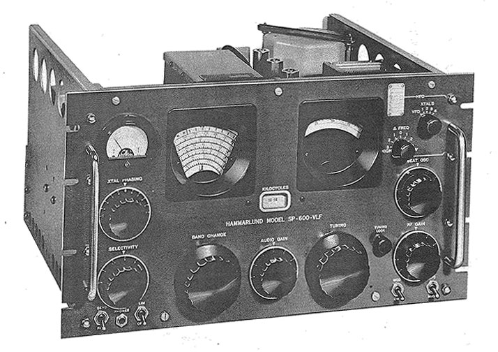
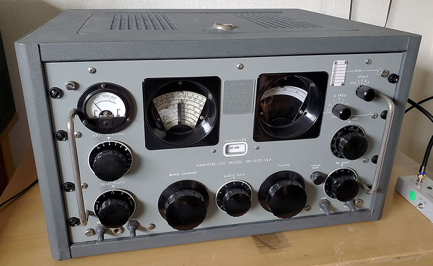
Total for SP-600VLF is now 37

________________________________

Dec 9, 2022     2215hrs to 2232hrs

WG 248kc Winnepeg, MB, CAN
XC  242kc Cranbrook, BC, CAN
BR  233kc Brandon, MB, CAN
HLE  220kc Hailey, ID
 

Cndx good, storm coming in, some "pops"
Tuned in 9 stations in 17 minutes of listening. 4 new NDBs shown above (all below 250kc.) Best DX probably POA in Hawaii but Manitoba is good DX too (QR also copied.)

Total for SP-600VLF is now 41

Dec 23, 2022    2205hrs to 2235hrs

JDM 408kc Colby, KS
YWB 389kc West Bank, BC, CAN
HAU 386kc Helena, MT
ON 356kc Penticton, BC, CAN
YXL 346kc Sioux Lookout, ON, CAN*
FF 337kc "Hamre" Fergus Falls, MN - new #383
XH 332kc Medicine Hat, AB, CAN
YQF 320kc Red Deer, AB, CAN

24 stations tuned in 30 minutes. Cndx Good.
7 new stations for the SP-600VLF shown above.
1 newly heard NDB, FF 337kc Fergus Falls, MN
being #383 after a very long "dry spell" - last new NDB was in Nov 2020.

Total for SP-600VLF is now 48

* I had YXL listed on Nov 1 and counted it in the total then but I've listed it again here since Nov 1 wasn't really a log. So 41+7=48 Total

___________________________________

Dec 25, 2022   2145hrs to 2215hrs

YCD 251kc Nanaimo, BC, CAN
VR 266kc Vancouver, BC, CAN
YPW 382kc Powell River, BC, CAN
SB 397kc San Bernardino, CA

17 stations tuned in 30 minutes. Cndx noisy until 2200hrs, then quiet. Pixel Loop N-S,
4 new, shown above.

Total for SP-600VLF is now 52

Dec 30, 2022  2205hrs to 2225hrs

LLD 353kc  Lanai City, HI

17 stations heard, 1 new shown above.
Pixel Loop E-W
Total for SP-600VLF is now 53

  ____________________________

Dec 31, 2022 to Jan 20, 2023

Intense storm on New Year's Eve with heavy, wet snow toppled my 40ft Locust tree onto outdoor wire antenna pulling it to the ground. Snow still on ground three weeks later. Just was able to get Locust tree remains cut up and removed Jan 18, 2023. For sometime now, I've suspected that the Pixel Loop's performance is down from former years. So, put up a sloper wire antenna 84 feet long on Jan 28.

_____________________________

Jan 28, 2023 2150hrs to 2220hrs

LW 257kc Kelowna, BC, CAN
PND 356kc Portland, OR
SIT 358kc Sitka, AK

84ft sloper wire antenna, cndx good

16 stations tuned in 30 minutes, 3 new

Total for SP-600VLF is now 56


Feb 13, 2023  2205hrs to 2230hrs

21 stations tuned in, none were new for the SP-600VLF. Best DX was WG in Winnepeg, MB. New antenna is a 240'x108' "T" wire antenna that provides strong signals and the noise level isn't too bad.

_____________________


19.


RACAL Communications Ltd


RA-17C-12 Receiver with RA-237-B  L.F. Converter

980kc to 30mc Standard RA-17 Coverage

10kc to 980kc with L.F. Converter

Triple Conversion Receiver, Double Conversion LF Converter

SNs: RA-17C-12 sn:N4144       RA-237-B sn:371

1961

(includes NDB reception log)


RA-17C-12 SN: N4144 with RA-237-B SN: 371

If the Hammarlund SP-600VLF has a rival, it's the RACAL RA-17C-12 with the matching LF Converter, the RA-237-B. Performance is actually better than the "600VLF" in some cases with "to the kilocycle" dial accuracy, the ability to tune the antenna preselector in the LF converter, triple conversion in the receiver and double conversion in the LF converter result in a very quiet noise floor along with better selectivity options plus the incredible continuous frequency coverage from 10kc up to 30mc. These British-built receivers were initially intended for the Royal Navy but their popularity and reputation made them favorites of both military and commercial users around the world. How could you not love a receiver that used the Wadley Loop? The "C" versions were built for North American users and utilize SAE screws and US-type tubes plus a few other minor changes to benefit NATO and North American users.
RACAL Engineering Ltd was a British company that was founded by Raymond Brown and George (Jock) Calder Cunningham in 1950. The company name was derived from the names of the founders RAy Brown and Geo. CALder Cunningham. In 1953, the British Royal Navy wanted Racal to build a couple hundred Collins 51J receivers for RN use. Racal wanted to use mostly British parts but Collins insisted that parts from the USA had to used. After an inspection of the (then) small Racal manufacturing facility, Collins refused to license the manufacture of the 51J by Racal. Dr. Trevor Wadley was called to help design a new receiver that would have the specs of the Collins 51J but be a new original design. The "Wadley Loop" was a method of using a fixed crystal oscillator and a VFO combining in three mixers with harmonics from the crystal oscillator and the incoming signal to create a "drift cancelling" circuit.

Although the Wadley Loop might be the "heart" of the RA-17, it's the elaborate Antenna-RF preselector circuit that allows the receiver's performance to be maximized for any frequency or antenna used. The preselector has a very Hi-Q and has six tuning ranges plus a variable tuning control. This allows exact tuning of the RF amplifier grid input which results in the absolute best transfer of antenna energy to the receiver's front end. The film-strip tuning dial is six feet long and covers 1000kc divided into 1kc divisions. Dial accuracy is to the kilocycle. 100kc calibrator, triple conversion, six selectivity positions from 13kc down to 100hz, +/- 8kc BFO, long-short AVC, RF/AF/S-unit meter functions, 22 tubes (23 tubes in UK version,) four AF outputs with a 3Z ohm 1W audio for external loudspeaker (USA and MK.3 versions,) built-in monitor speaker (with off switch,) 100kc IF output were some of the features on the RA-17 receivers.  

The RA-17 was the first successful receiver to employ the "Wadley Loop" system for oscillator and conversion stability. The first British Royal Navy RA-17 receivers supposedly cost £ 300 each, an equivalent cost then of about $1500. The RA-17 was produced from around 1957 up to around 1973. The RA-17 was upgraded several times but also many variations were produced that were built for special purposes or to be used with other specific equipment. The RA-17 "C series" was built for North American use with standard US-type tubes and US-compatible hardware. 

Racal also produced many different types of accessory equipment for the RA-17, e.g., VLF/LF/MF converters, digital frequency readouts using Nixie tube displays, panoramic adapters, SSB adapters, diversity equipment, RTTY equipment and many other devices. Racal's official name changed several times over the years. Starting out as Racal Ltd, then Racal Engineering Ltd, then Racal Communications, etc., many variations. At one time, Racal employed 30,000 workers building many different types of electronics (not just radio equipment.) It was the third largest electronics firm in Britain and had facilities in 110 different countries. Calder Cunningham died in 1958 and, in 1966, Ray Brown accepted a political position in British government Ministry of Defense, retiring from the company. After 1966, Ernest Harrison was in charge of Racal. The company also owned Decca, Chubb and Vodafone to name a few of their holdings. Several reorganizations and division sales occurred in the 1990s and, in 2000, Thomson-CSF (aka Thalen Group) purchased the bulk of Racal Electronics.

L.F. Converter Type RA-237-B Circuit - There was a RA-137 LF converter that proceeded this later version, the RA-237-B. This version was designed to work with either the RA-17 or the RA-117 receivers. The "B" indicates that this LF converter was built in England for North America-use and was equipped with USA-type tubes, hardware and connectors.
 
The RA-237-B LF converter is connected via a coaxial cable to the 1mc crystal oscillator of the RA-17 using the BNC connector marked "1mc" on both units. The 1mc oscillator is then routed to a LF Harmonic generator and to a 2mc bandpass filter that passes the second harmonic of the 1mc oscillator. This 2mc signal is combined in the converter's Mixer stage along with the RF Amplifier output. The output of the converter's Mixer is essentially a tunable 2-3mc signal that is connected to the RA-17's 2nd IF amplifier which is also tunable 2-3mc. The 2-3mc signal is then routed through the remaining RA-17 circuitry. LF tuning is accomplished with the Kilocycle tuning on the RA-17 referencing the "red scale" on its tuning dial. The Megacycle tuning of the RA-17 is not active when the converter is being used so the position of the Megacycle tuning is not important. AVC from the RA-17 is wire-connected to the RA-237-B and controls the RF Amp if desired. Manual gain control can also be used. HT1 and HT2 are +250vdc routed from the RA-17 (wire-connected) through the OPERATION toggle switch of the RA-237-B to allow selecting either RA-17 normal operation (980kc-30mc tuning) or RA-17 + RA-237-B operation (10kc to 980kc tuning.)
Operation - With the RA-17 turned on and the RA-237-B power on, select "10kc to 980kc" with the OPERATION toggle switch. Using the Kilocycle tuning and observing the red scale on the RA-17 dial select a frequency, e.g. 350kc. On the RA-237-B, using the ANT RANGE switch, select 210kc to 500kc range. Using the RA-237-B ANT TUNING, adjust the dial to read approximately 350kc. As you near 350kc, the background noise in the RA-17 will increase and will peak somewhere near 350kc as read on the RA-237-B dial. As you search for a NDB station with the RA-17, peak the RA-237-B every 5kc or so. The converter's preselector circuit has a very high Q and the tuning is very sharp. The frequency is read directly on the red scale of the RA-17 and the approximate antenna peaking frequency is read on the RA-237-B dial. With very weak signals, switch off the AVC and control the front end gain manually. This will prevent the noise level from controlling the AVC and reducing the front end gain. Manual control also is necessary during very noisy conditions. The Hi-Q ANT TUNING is narrow enough to reduce a lot of the LF reception noise in most cases and AVC can be used during good conditions and moderate signal levels. If you want to return to HF just switch the OPERATE toggle switch to 980kc to 30mc position and the RA-17 front end takes over and allows HF reception.
Comparison of the RACAL RA-17C-12 & RA 237-B to the Hammarlund SP-600VLF-31 - As mentioned above,...if the SP-600VLF has a rival, it's the RACAL RA-17C-12 with the RA-237-B LF Converter. First, the RACAL combo has "to the kilocycle" dial accuracy which, of course, the SP-600VLF-31 doesn't. This dial readout accuracy is very useful when looking for specific MW stations or other "known frequency" stations. When using the SP-600VLF, the logging dial must be used for accurate frequency resetability which requires finding the station first, then noting the logging dial for future listening. The RACAL combo has a wide choice of selectivity - from 13kc bandwidth down to 100hz bandwidth. The SP-600VLF always has the Crystal Filter "in circuit" with the widest bandwidth being 6kc but that even sounds much narrower. When tuning the RACAL combo, one is always keeping the antenna load tuned resulting in the best transfer of energy from the antenna. Like all Super Pro receivers, the SP-600VLF is a fixed impedance at the antenna input which is impossible to match with a wire antenna but pretty easy using the Pixel Loop. The RACAL combo will tune continuously from a low of 10kc up to 30mc and the receiver is triple conversion (when tuning 1.0mc to 30mc) while the LF Converter is double conversion resulting in a very quite noise floor. The SP-600VLF is 10kc to 540kc and, while it is a double preselection front-end, it's only single conversion which tends to make the SP-600VLF have a rather high noise floor. Audio output impedance on the RACAL is three different 600Z outputs but there is a 3.2Z output also. The SP-600VLF is 600Z only. Finally, there's the expense of purchasing a Hammarlund SP-600VLF,...if you can find one for sale. A good, working example will sell for $2000 or possibly more. The RA-17C-12 usually sells for between $400 and $800 and the LF converters usually sell for $200 to $400. If there's a disadvantage to the RACAL combo, it's maintenance. These receivers are complex and they are difficult to take apart. Though modular in construction none of the modules just "unplug" - there's always some wires that will need to be unsoldered for complete removal. Many of the components are buried inside modules that have to be entirely removed from the receiver to have access. Alignment is time consuming and requires accessing adjustments almost everywhere on top, on the sides and underneath the receiver chassis. The RACAL "C" versions were built for NATO/North America and will have USA compatible fittings, hardware and vacuum tubes but still some parts are exclusively British RACAL and difficult to find, if needed. For reliability and performance, both receivers are excellent. Both receivers work extremely well with a Pixel Loop antenna.
NDB Reception Logs from November 10, 2019 to Dec 10, 2019 - Below are reception logs for the RA-17/RA-237-B combo. The first four logs are with an outside wire antenna. Remaining logs are with Pixel Loop.

Reception Log for November 10, 2019  -  2150-2215hrs PST  -  Ant 135' "T"

1. YTL 328kc - Big Trout Lake, ON, CAN
2. VT 332kc - Buffalo Narrows, SK, CAN
3. DB 341kc - Burwash Landing, YK, CAN
4. RYN 338kc - Tuscon, AZ
5. YZH 343kc - Slave Lake, AB, CAN
6. POY 344kc - Powell, WY
7. SBX 347kc - Shelby, MT
8. YXL 346kc - Sioux Lookout, ON, CAN
9. NY 350kc - Enderby, BC, CAN
10. IN 353kc - International Falls, MN
11. YWP 355kc - Webequie, ON, CAN
12. ZF 356kc - Yellowknife, NWT, CAN
13. YQZ 359kc - Quesnel, BC, CAN
14. RPX 362kc - Roundup, MT
15. YMW 366kc - Maniwaki, QC, CAN
16. ZP 368kc - Sandspit, Queen Charlotte Islands, BC, CAN
17. EX 374kc - Kelowna, BC, CAN
18. CNP 383kc - Chappell, NE
19. YWB 389kc - West Bank, BC, CAN
20. PNA 392kc - Pinedale, WY
21. YL 395kc - Lynn Lake, MB, CAN
22. ULS 395kc - Ulysses, KS
23. ZSS 397kc - Yellowhead-Saskatoon, SK, CAN
24. FN 400kc - Ft. Collins, CO
25. QQ 400kc - COMOX Vancouver Is., BC, CAN


Reception Log for November 11, 2019  -  1920-1950hrs PST   -   Ant 135' "T"

1. UAB 200kc - Anahim Lake, BC, CAN
2. LU 213kc - Abbottsford, BC, CAN
3. EL 242kc - El Paso, TX
4. XC 242kc - Cranbrook, BC, CAN
5. QL 248kc - Lethbridge, AB, CAN
6. YCD 251kc - Nanaimo, BC, CAN
7. LW 257kc - Kelowna, BC, CAN
8. VR 266kc - Vancouver, BC, CAN
9. XS 272kc - Prince George, BC, CAN
10. YYF 290kc - Penticton, BC, CAN
11. TOR 293kc - Torrington, WY
12. DC 326kc - Princeton, BC, CAN
13. MA 326kc - Midland, TX
14. RYN 338kc - Tuscon, AZ

Reception Log for November 13, 2019  -  2220-2235hrs PST  Ant 135' "T"

1. LYI 414kc - Libby, MT
2. FQ 420kc - Foremost, MN
3. ATS 414kc - Artesia, NM - 25W
4. ZQ 410kc - Sir Wilfred Laurier, Canada Coast Guard Ship, BC, CAN
5. Z7 408kc - Claresholm, AB, CAN
6. MW 408kc - Moses Lake, WA
7. YLJ 405kc - Meadow Lake, SK, CAN
8. AZC 403kc - Colorado City, AZ
9. L4 402kc - Nipawin, SK, CAN - 200W  < newly heard station #345


Reception Log for Nov. 20, 2019 from 2150-2220 PST netted 36 stations logged about 30 minutes, tuning from 326kc up to 410kc. Listed here are only the newly heard stations using the RACAL set up. Other stations heard in this session are listed in the other logs.

1. YPO 401kc - Peawanuck, ON, CAN
2. JDM 408kc - Colby, KS  25W
3. YJQ 325kc - Bella Bella, BC, CAN
4. X2 328kc - Athabasca, AB, CAN
5. YY 340kc - Mont Joli, QC, CAN
6. XX 344kc - Abbotsford, BC, CAN
7. PA 347kc - Prince Albert, SK, CAN
8. LLD 353kc - Lenai City, Hawaii
9. AL 353kc - Trina, WA
10. ODX 355kc - Ord, NE  25W
11. YAZ 359kc - Tofino, Van Is, BC, CAN
12. SX 367kc - Cranbrook, BC, CAN
13. DPY 365kc - Deer Park, WA  25W
14. AA 365kc - Fargo, ND

NOTES:

11-10-2019 - Cndx were very good with fairly low noise
11-11-2019 - Cndx noisy probably due to the time I was listening
11-13-2019 - Cndx were very good with fairly low noise
11-20-2019 - Cndx were very good with low noise

Total NDBs logged with a wire antenna - 61

Antenna for these four sessions was the 135' "T" which is an 80 meter Inv Vee fed with 99' of ladder line with the ladder line wires tied together and connected to the center conductor of the Antenna Input of the RA-237-B.


NOTE: I've checked 630M (472kc to 479kc) several times and have only heard JT9 signals, no CW signals,...yet.

Performance - The RA-17 and RA-237-B combination works amazing well for LF reception. The reception logs show NDB stations received with a wire antenna which usually presents a fairly high noise level. However, the very Hi-Q of the preselector in the RA-237-B helps to reduce noise as does the double conversion scheme. None of the listening sessions were longer than 30 minutes and the total NDBs tuned in was 61 stations (RYN 338kc is listed in two sessions.) The 200kc to 300kc region has a higher noise level and also fewer operating NDBs which accounts for the fewer stations in that log. Tuning only 18kc of the 400kc region produced nine NDBs, one of which was a newly heard NDB (L4 402kc,... #345.) I'd have to rate the RA-17 and RA-237-B as a really fine set-up for LF listening. The manual specs the sensitivity for the combo at 1uv for A1 and 3uv for A2 which is certainly believable, although noise levels in the MW, LF and VLF regions don't allow reception of signals at that level of sensitivity. I'm sure with a noise reducing antenna such as a "tuned loop" even better DX could be achieved. But still, the wire antenna performance is impressive. Frequency readout is right-on, amazing accuracy but, like the R-390A, you have to add or subtract the BFO setting. 600Z phones were plugged into the front panel jack(s) for reception.

UPDATE Nov 30, 2019 - I've started using a Pixel Technologies Shielded-Magnetic Loop antenna with the Racal LF combo. So far, the performance of the loop has allowed receiving NDBs east out to Quebec and west to Hawaii. More details as more testing is completed. The Pixel Loop is profiled in the "Loop Antenna Designs" section in Part 4 of Vintage LW Receivers.

UPDATE Dec 6, 2019 - Below is the reception log for Dec 5, 2019 using the RACAL RA17/RA237B with the Pixel Loop. The loop was indoors (second floor) and pointed NE. Conditions were great. 28 NDBs logged in a 25 minute session. One newly heard station, YFM 332kc LaGrande, Quebec, #347. I also logged another newly heard station with the Pixel Loop/RACAL setup a few days earlier, PMV 329kc Plattsmouth, NE, #346

Reception Log for Dec 5, 2019, 1905hrs-1930hrs PST using Pixel Loop


1. YWB 389kc - West Bank, BC,CAN
2. PNA 392kc - Pinedale, WY
3. TW 389kc - Twin Falls, ID
4. JW 388kc - Pigeon Lake, AB, CAN
5. HAU 386kc - Helena, MT
6. QV 385kc - Yorkton, SK, CAN
7. PI 383kc - Tyhee, ID
8. MR 385kc - Monterey, CA
9. GC 380kc - Gillette, WY
10. YE 382kc - Fort Nelson, BC, CAN
11. EX 374kc - Kelowna, BC, CAN
12. YBV 370kc - Berens River AP, MB, CAN
13. AA 365kc - Fargo, ND
14. SX 367kc - Cranbrook, BC, CAN
15. ZP 368kc - Sandspit, Queen Charlott Is., BC, CAN
16. DPY 365kc - Deer Park, WA
17. RPX 362kc - Roundup, MT
18. YQZ 359kc - Quesnel, BC, CAN
19. ODX 355kc - Ord, NE
20. IN 353kc - International Falls, MN
21. PG 353kc - Portage, MB, CAN
22. NY 350kc - Enderby, BC, CAN
23. YXL 346kc - Sioux Lookout, ON, CAN
24. YZH 343kc - Slave Lake, AB, CAN
25. YY 340kc - Mont Joli, QC, CAN
26. RYN 338kc - Tuscon, AZ
27. ZU 338kc - Whitecourt, BC, CAN
28. YFM 332kc - LaGrande 4, QC, CAN < newly heard station #347
 

Reception Log for Dec 8, 2019, 1910hrs-1940hrs PST using Pixel Loop - 27 stations received (only stations not listed in previous logs are shown)

Reception Log for Dec 10, 2019, 1905hrs-1935hrs PST using Pixel Loop - 22 stations received  (only stations not listed in previous logs are shown)

1. ZZD 308kc - Edmonton IAP, AB, CAN
2. YIV 300kc - Island Lake, MB, CAN
3. Z1 305kc - Three Hills, AB, CAN 25W < newly heard station #348
4. UNT 312kc - Penticton, BC, CAN
5. YQF 320kc - Red Deer, AB, CAN
6. LGD 296kc - LaGrande, OR 25W
7. YER 334kc - Fort Severn, ON, CAN 195W < newly heard station #349
8. YLD 335kc - Chapleau, ON, CAN
9. MEF 356kc - Medford, OR
 

Total NDBs logged with RACAL setup - 94 (Nov 10 to Dec 10, 2019)

1. YNE 207kc - Norway House, MB, CAN 1KW < newly heard station #350
2. IB 209kc - Atikokan, ON, CAN
3. RL 218kc - Red Lake, ON, CAN
4. YKA 223kc - Kamloops, BC, CAN
5. CG 227kc - Castlegar, BC, CAN
6. BR 233kc - Brandon, MB, CAN
7. XE 257kc - Saskatoon, SK, CAN
8. ZSJ 258kc - Sandy Lake, ON, CAN
9. GEY 275 - Greybull, WY
10. NM 278kc - Matagami, QC, CAN
11. CEP 278kc - Ruidoso, NM
12. QR 290kc - Regina Int'l. AP, SK, CAN
A Second RA-237-B in combination with a RA-17C Mark II Receiver - I've had the RA-17C Mark II (1959 vintage) for quite a while but I just came across this second RA-237-B in February 2022. It had a broken wire inside the Balanced Mixer that was causing it to not function at all (and why it was bargain-priced - $125.) The big problem was the missing dial bezel. I had to make a dial bezel out of white 0.25" half-round plastic rod material. The finished bezel had to be painted black before installation. The end result looks original,...well, almost original.

Below is a reception log for the RA-17C Mark II in combination with this RA-237-B LF Converter.

Mar 5, 2022 - 2155hrs to 2225hrs

DC 326kc Princeton, BC, CAN
MA 326kc Midland, TX
XH 332kc Medicine Hat, AB, CAN
RYN 338kc Tucson, AZ
OIN 341kc Oberlin, KS
XX 344kc Abbotsford, BC, CAN
LLD 353kc Lanai City, HI
MEF 356kc Medford, OR
RPX 362kc Roundup, MT
PI 383kc Tyhee, ID
CNP 383kc Chappell, NE
FN 400kc Ft. Collins, CO
MOG 404kc Montegue, CA
MW 408kc Moses Lake, WA
ATS 414kc Artesia, NM

Conditions are rapidly deteriorating as the LW Season is winding down. Signals noticeable weaker and the noise much higher.

Pixel Loop antenna pointed NE-SW and 600Z phones. Best DX was LLD 353kc in Lanai City, Hawaii.


Photo Right - The RA-17C Mark II receiver with the RA-237-B LF Converter with the replica bezel installed. 

I used Krylon Gloss Black for the bezel paint. To keep the glue job straight, I first put a strip of blue masking tape at the top of the panel that defined a straight top edge position for the bezel. Then I marked two edge limits on the tape for the horizontal position of the bezel. A very small amount of epoxy was used to glue the bezel to the panel. The bezel turned out very well even though it's not exactly like the originals,...well, only experts would know,...right?

Also, the original RACAL tag was found in the shipping box - it had fallen off the panel during transit. So, it's also installed back where it originally was.


RA-17C Mark II SN: N1654 with RA-237-B SN: 308


20.


EDDYSTONE

Stratton & Co. Ltd.

 Model 850/2

Receiver #1 - Type S850/2  sn: DEV0003
Receiver #2 - Type S850/2  sn: IN0024


MW, LF & VLF Receiver
Single Preselection,
 Single Conversion Superheterodyne
10kc to 600kc
 

1961


Eddystone Model 850/2  SN: DEV0003

Eddystone Radio

Before Radio - Eddystone Radio can trace its beginnings back to 1860 with the partnership-business of Jarrett & Rainsford in Birmingham, England. This company made women's hair pins and costume jewelry. In 1898, a 15 year old George A. Laughton joined the company. By 1904, Laughton was an assistant manager. In 1911, Laughton bought a small merchandise supplier company that was going derelict for £ 50 and renamed that company "STRATTON & CO., LTD." (apparently naming the company after his young son, Stratton Laughton.) During WWI, Stratton & Co. supplied aluminum for the construction of SE5 airplanes and, after WWI, Jarrett, Rainsford & Laughton Co. combined with Stratton & Co., Ltd. with the latter becoming a subsidiary (1919.)

Stratton & Co., Ltd. - Radio 1922 to 1939 - From about 1922 to 1925, Stratton & Co. made various types of radio component parts after becoming involved with the BBC in 1922. It's thought that Stratton Laughton's interest in wireless might have also helped to fuel the company interest in radio. In 1925, Stratton & Co. came out with their first completely built radio set for sale to the public. In February 1925, Stratton & Co. registered the "EDDYSTONE" name and the "Lighthouse" Trade Mark (there actually is an Eddystone Lighthouse located near Cornwall, England. It was constructed in 1882.) 

By 1927, Eddystone had started to move on to shortwave radios and by 1930 sold no more radios that tuned only MW (Broadcast sets.) In the early 1930s, Eddystone SW radios were used in several British expeditions like the British Arctic Air Route Expedition. In 1935, Eddystone moved into VHF and started to supply police cars with two-way VHF radios. Just before WWII, Eddystone had set up a wireless telephone link for several police stations and Scotland Yard inter-communications in London.

Post-WWII and After - During WWII, Eddystone produced 4500 transmitters, 7264 receivers and 45,000 other items for the war effort. But, after WWII, the abundant surplus radio equipment availability seriously affected new radio sales, so Eddystone went on to specialize in professional commercial-military types of radio gear that were produced with high-quality construction and good stability as the main factor and selling price a secondary consideration. In 1964, George A. Laughton died and the following year, Eddystone was sold to Marconi Communication Systems. Marconi continued on supplying professional-level equipment with the Eddystone name but eventually sold Eddystone to Megahertz Communications in 1999, who, in turn, sold the company to Ring Communications. The final owner was Sound Broadcasting Systems, who is still the current owner.


An artist's representation of the Eddystone Lighthouse as part of the TM logo.

Model 850/2 History - The 850/2 was built for use onboard submarines and ships, at coastal stations or other military or commercial sites that required a receiver that tuned from 10kc up to 600kc. Marine Band communication on commercial ships was also a possibility. Some types of navigation signals along with VLF submarine data communications were all possibilities. Even LW-BC could have been tuned, if needed. But, certainly there wasn't a huge demand for LW receivers, even in 1961. Since it was such a "special use" piece of equipment, Stratton & Co. only built 100 Eddystone Model 850/2 receivers. Apparently, Eddystone also produced a Model 850/4 that is almost identical to the Model 850/2. It's unknown how many "/4" versions were built. It might be possible that the "/4" is included in the total of 100 receivers since the "/4" is virtually unknown.

Model 850/2 Circuit - The 850/2 is a single preselection, single conversion superheterodyne receiver that tunes from 10kc up to 600kc in six tuning ranges. The receiver uses 11 vacuum tubes and two glass tube-envelope quartz crystals. A converter tube is used to combine the LO and Mixer functions. Two IF amplifier stages operating at 720kc are used. Three steps of selectivity are available with a 6kc bandwidth for Voice (not much of that on LW anymore) and two selectable crystal filters provide 1.5kc and 0.4kc bandwidths. Two detectors are provided, one for AM using a standard diode envelope detector and another for CW using a product detector (a 6BE6 mixer tube.) A Carrier Level meter is provided. The Noise Limiter is the typical clipper-type good for pulse noise only. The audio output is about 1 watt and the output impedance is 2.5Z with a 600Z line output (possibly to drive data devices) and a 2000Z 'phones output (C-coupled from the 6AM5 AF output tube plate.) The receiver uses mostly USA-type tubes with British equivalents shown in the manual.

The receiver has separate RF, IF and AF gain controls. The RF/IF gain controls are on a coaxial shaft with the RF gain using the front knob which is a solid red knob or a black knob with red colored index. Antenna input impedance is either 75Ω or 300Ω and an Antenna (Aerial) Trimmer is provided. A muting circuit (desensitizing) has rear chassis terminals for its use. A voltage regulator tube is used (VR-150/0D3) and the power transformer has a dual primary for 110vac or 220vac operation (on standard production models.) 

Mechanically, the 850/2 uses die-cast aluminum front panel that has a large slide-rule tuning dial that is 13" wide with a logging dial system that provides 2300 divisions for accurate frequency reset. The chassis is actually made of of three individual sub-chassis that are bolted together. The central chassis is die-cast aluminum and houses the RF front end and tuning condenser. The IF/AF chassis is made out of brass while the Power Supply chassis is made out of steel. Since all three chassis are painted gray on all sides, it's not readily apparent that different metal materials are used in the construction.


photo above
: The top of the 850/2 chassis of IN0024. The left side is the power supply chassis. Note the standard production power transformer and the movable jumper for selecting primary voltage. The smaller can with the tube on top is the BFO. The center chassis is cast aluminum with V1 RF amp and V2 Converter tubes and the tuning condenser located under the shield-cover. The right side chassis has the two crystal filter assemblies in front (the crystals look like vacuum tubes and have tube shields installed.) The three IF transformers are in the center and the audio output transformer is rearmost. The missing 5Z4G rectifier tube has a solid-state replacement installed (next to the 0D3 regulator tube.) I've installed a 5V4G rectifier since this photo was taken.

Rear Chassis Connections - The input and output connections use push-terminals so the wires don't need crimp-lugs or wraps secured with a screw. Just push in the terminal top and insert a bare-tinned wire into the hole and release.
600Z Output
,...the 600Z ohm winding on the output transformer can have a resistive load added by inserting a jumper across the "LINK" terminals. This is used as an attenuator for the LINE OUT 600Z but accomplishes that by connecting a 630 ohm resistor network across the winding. 
2.5Z Output
,...although the 2.5Z winding is only marked as "2.5Ω" at the terminals, the right terminal connects to chassis and the left terminal goes to the transformer winding. 
Antenna Input
,...four terminals are used for the antenna connections. A 300Ω and a 75Ω then a return terminal and another terminal for chassis. This was to allow either a balanced or unbalanced antenna and feed line to be used. By connecting the balanced line to the two top connectors a 300Ω input impedance is provided. By connecting to the two left side vertical terminals a balanced 75Ω was provided. The right side lower connector was chassis and by connecting that terminal to the upper left terminal 300Ω unbalanced was provided at the upper right terminal. Lower left terminal against lower right terminal (chassis) would provide 75Ω unbalanced. This description is for IN0024. DEV0003 as shown in the photo to the right. 
Muting
,...a jumper link must be connected across the two DESENSITIZING terminals for normal operation. These terminals can go to a NC relay contact if the receiver was used along side a transmitter to provide muting. Open contacts on the relay would mute the receiver.


Audio & AGC Outputs

S-meter Adj. & IF output

LINK across 600Z places a 600 ohm resistor network across output transformer as an attenuator


Antenna Input on IN0024

Jumper installed diagonally as shown
to allow 75Z unbalanced or 300Z
unbalanced from unused terminals. This is the standard production Antenna Input configuration


Antenna Input on DEV0003

Jumper can be installed between the two left side terminals to allow unbalanced
300Z or 75Z on right side terminals
 

SN: IN0024

This 850/2 is the first version of the Eddystone LW receiver I was able to obtain. It wasn't complete and had several cosmetic issues, some of which were unsolvable - like the missing cabinet or the oxidized paint on the dial scale. But, it functioned fairly well and piqued my interest in what the capabilities of the design could be.


Model 850/2 SN: IN0024

Model 850/2 History for IN0024 -  The receiver shown in the photographs is serial number IN0024, or the 24th receiver built. Note that the Model is shown as "TYPE  S850/2" on the data plate however the manual and all other written information refers to the receiver as "Model 850/2." The data plate is shown in the photo below. I suspect that IN0024 originally might have been a rack mount version. The location of the data plate is on the rear chassis apron instead of on top of the tuning condenser box. The rack mount version came equipped with rack flanges that somehow bolted to the back of the front panel and had relief cut-outs in the shroud-cover. Both the shroud-cover and rack flanges are missing.

The Property Asset Tag - Note the small red and silver property tag at the upper right corner of the front panel,...this property asset sticker has "PROPERTY OF AERONUTRONIC" at the bottom of the tag. Aeronutronic Systems, Inc. was a division of Ford Aerospace that was established around 1956. When Ford bought Philco around 1961, they merged Aeronutronic with Philco-Ford and, in 1963, the name was changed to "PHILCO AERONUTRONIC" and that company became NASA's main contractor for communications systems. Although they had a history of working with NASA communications systems, it seems many other projects were in military defense, like the Sidewinder, the Minuteman and the Trident Missile programs. The company became Ford Aerospace & Communications in 1976 and then Ford Aerospace in 1988. The company was purchased by Loral in 1990 and then sold to Lockheed-Martin in 1996. Why an aerospace-communications company would have needed a British MW-LF-VLF receiver is unknown.


photo left: Note the differences between IN0024 and DEV0003. No red RF gain knob is the most obvious. The "Made in England" is not under the EDDYSTONE tag. Other differences are the power transformer, the data plate location and rear panel terminals.

MAINS Input Socket - The Eddystone AC power input socket is unusual and, although it might be a common plug in England (though it doesn't seem to be,) I've never seen a mate for this type of socket. To avoid long delays caused by fruitless searching, I decided to just make custom-fit "push-on" connector plugs for each contact. I used spring-copper salvaged from the ends of copper alligator clips. These are designed to fit banana plugs and are relatively close in size to begin with. Altering to the correct diameter involved using the shank of drill bits that were the same size at the Eddystone Mains pins. The copper connector was sized using a combination of vise-grips and needle-nose pliers. I made the fit rather tight but still removable. For the blade ground connection I used a standard push-on spade lug receptacle that was the correct size. Once the connecting socket pins were made I then soldered them to the three-conductor AC line cable and afterwards sleeved them with shrink-tubing. The AC cable was secured using a cable clamp mounted with an existing screw on the rear panel to prevent cable wires from moving at the Mains socket (although they are a really "tight fit.") 

Data plate for IN0024

Dial Glass and Dial Scale Issues - These problems are minor but to correct them is a major undertaking. The glass dial cover is chipped in two places. It's not really too noticeable but, since the glass is just a flat pane of glass, it would be easy to cut a new one and replace the chipped one (or, so I thought.). The second problem is related to the first, sort of,...the dial scale and the dial area are very dirty (or, so I thought.) Lots of debris inside. I'm sure this has been collecting since the receiver first left the factory since removing the front panel to do any work on the dial system is so incredibly difficult. Apparently, Eddystone thought everyone would keep their receivers in a nice tidy area with no dust, no dirt or other contaminates so they designed the front panels to have the dial drive gearbox and the dial string-pulley system mounted to the back of the cast aluminum panel and then make it a labor intensive puzzle to access any of it. There are mounting screws that are located under the decorative control nomenclature panel that requires dismounting all of the knobs and controls first to begin removal of that panel (and the nomenclature panel is "tack glued" - double-sided tape used for this receiver - to hold it in place so a light touch is necessary to avoid bending it during removal.) Also, since the dial drive gear box is part of the front panel, the flex-coupler to the tuning condenser has to be loosened. Then there are the screws that mount the grab handles that are accessed from the backside of the front panel from inside the chassis and the counter-sunk screws that only can be accessed after the nomenclature panel is removed. Once the front panel is dismounted, then the dial drive assembly has to be dismounted to have access the glass dial cover and to clean the dial scale area. This is such a daunting job that nobody has tackled it since the receiver was built. I'm still considering if it's worth the risk of more serious damage to even try to disassemble the front panel puzzle. And then,...another problem,...I did decide to take the challenge and do the front panel dismount. I removed the knobs and, of course, all knobs came off easily except for one,...the SELECTIVITY knob. A close look and it was obvious that the set screw was half-broken so a blade screw driver had no slot to go into. Since the knobs are unique to Eddystone (and not easily found here in the USA) extraction of the broken set screw does present a problem. Because the set screw break has left half of the slot wall present there isn't a "centered" flat surface for the drill bit. It will be necessary to drill the smallest hole possible into the set screw and work up the diameter in small steps. Perhaps, once the hole is large enough, a reverse flute drill might work. But usually, if the set screw has been "over-tightened" (and that's usually the case when automobile mechanics work on radio equipment) the force necessary to loosed the set screw can't be achieved with the reverse drill bit or a with a screw extractor. Drilling out the set screw entirely is usually all that works but many times the knob is damaged during the process. If I had a duplicate replacement knob, I'd just use the Dremel tool and cut-off wheel and have the knob removed in about 30 seconds.

For now, I'll wait on the front panel removal and dial clean-up until I come up with a better set of tools for extracting tiny little set screws, or, until a duplicate knob turns up somewhere.

More on the front panel removal a little further down in this write-up.

Minor Modification Encountered when Replacing the SS Rectifer - In checking on installing a vacuum tube rectifier, I decided to sub a 5V4G tube for the 5Z4G since I have several of the former and none of the latter. With the 5V4G installed, no filaments and no high voltage. A check under the chassis revealed that a previous owner had disconnected the 5vac 2A winding from the rectifier tube socket and had reconnected it into the primary winding of the power transformer to act as a "line bucker." It's a good idea to reduce the high line AC voltages of today on any vintage receiver but especially with the Eddystone since its power transformer primary has a rating for 110vac input. However, I always use an external line bucker on vintage receivers (and I have several line buckers,) so one is unnecessary in the receiver and prevents using a vacuum tube rectifier that sort of "soft starts" the B+. The return to a tube rectifier was simple since none of the wiring was cut, just moved. Since the first testing of the receiver was accomplished with my external line bucker connected, the actual AC input to the primary of the power transformer was quite a bit less than 110vac. Now, with the tube rectifier "in use" the AC input is 115vac which is better for the tube heaters and is still well-within the specs shown in the manual for AC input voltage. Additionally, the slightly increased HV level more than compensates for the increased voltage drop from the 5V4G rectifier tube. At any rate, the receiver performance seems noticeably better, although I'm sure that the very low AC input from "double line buckers" was responsible for the slightly lower output levels and the "average" level of sensitivity.

In the meantime, some performance testing,...


Initial Performance - Using a 162ft end-fed wire antenna I tuned in all of the typical LW signals without too much trouble. The BFO wasn't set-up for zero but it did function. I set for a zero beat and was able to hear the USN MSK stations around 24kc, WWVB on 60kc and a few AM-BC stations that are below 620kc. This was just a test to see how the 850/2 functioned. That night I listened for NDBs and was able to copy several. The best USA DX was OIN 341kc in Oberlin, KS and the Canadian NDBs heard were all in British Columbia. But, I wasn't looking for really weak signals since I was using the wire antenna, I was just checking operation. The next day I calibrated the BFO by injecting a 720kc signal with the receiver in the 0.4kc bandwidth position. The BFO air variable was set to half-mesh, the BFO air variable mounting nut was tightened (this loose nut was the reason the BFO wouldn't hold the zero set,) the knob repositioned to "0" and the slug in the BFO can adjusted for zero beat. This resulted in the BFO operating in a normal manner.

I injected test signals using the HP-606 RF Signal Generator that were measured using a DFC and then checked the RF tracking of the receiver. For the most part, the typical error was about 1.5kc to 2.0kc on Bands 1 and 2 which is very good (the two highest frequency bands.) The error on Band 5 is about half a kilocycle but that's actually quite a lot at 24kc. Most RF signal generators don't cover VLF with the lower limit usually being about 50kc or so. Many times, the VLF bands on LW receivers haven't been aligned due to a lack of suitable equipment. But, I have the General Radio Type 1001-A RF Sig Gen that has the lower frequency limit of 5kc, so alignment on Bands 4, 5 & 6 will require using that GR instrument. An inspection showed that Bands 5 and 6 still had the original sealing wax on the adjustments (so, they've never been realigned since the factory alignment 60 years ago.) I'll probably do a complete servicing of the 850/2 that includes tube testing and a complete alignment. But first, I need to do some more test listening to see if any other issues turn up. A couple of logs are shown to the right (using the Pixel Loop antenna.) I started pretty late in the LW Season so signals were weaker and noise levels somewhat higher than a month earlier, even using the Pixel Loop. The "blowtorches" like MOG, XX or RYN are still strong, just the DX signal levels are dropping fast.

Feb 27, 2022 - 2200hrs to 2225hrs PDT

LYI 414kc Libby, MT
MW 408kc Moses Lake, WA
MOG 404kc Montegue, CA
PNA 392kc Pinedale, WY
YWB 389kc West Bank, BC, CAN
HAU 386kc Helena, MT
MR 385kc Monterey, CA
PI 383kc Tyhee, ID
GC 380kc Gillette, WY
SX 367kc Cranbrook, BC, CAN
AA 365kc Fargo, ND
SB 362kc Sudbury, ON, CAN
RPX 362kc Roundup, MT
MEF 356kc Medford, OR
XX 344kc Abbotsford, BC, CAN
YY 340kc Mt. Joli, QC, CAN
RYN 338kc Tucson, AZ
QT 332kc Thunder Bay, ON, CAN
DC 326kc Princeton, BC, CAN
ZZD 308kc Edmonton Intn'l AP, AB, CAN

Pixel Loop Antenna to 75Ω input. Cndx good but getting close to the end of the LW season. Hi-Z Trimm phones used.

20 stations in 25min. Best DX was YY 340kc located at Mt. Joli, Quebec (just N of Maine.)

Mar 6, 2022 - 2215hrs to 2235hrs PDT

GRN 414kc Gordon, NE
FN 400kc Ft. Collins, CO
TW 389kc Twin Falls, ID
YXL 346kc Sioux Lookout, ON, CAN


Pixel Loop Antenna pointed NE-SW.
Trimm Hi-Z phones.
LW season is really coming to an end fast.
Conditions were okay but DX signals were very weak.

13 stations tuned in 20 minutes of listening
4 stations were newly heard on the 350/2
and are shown above.

Best DX YXL 346kc at Sioux Lookout, Ontario, Canada

Total for the 350/2 is 24 stations (but the total listening time equals only about 45 minutes for the two listening sessions.)


Alignment Assessment - June 3, 2022 - A quick test involved using the HP-606B RF signal generator connected to a radiating wire while the receiver was connected to an end-fed wire antenna that was attached to the 300Z input. Band 1 seemed to perform pretty well with this setup but Band 2 and Band 3 were way down is sensitivity. Band 4 and Band 5 performed quite well although Band 5 performance was based on reception of the USN MSK stations. Band 6 tunes 10kc to 20kc so testing it will require the GR-1001-A RF sig gen. I think the varying antenna Z versus the received frequency might have been causing the problems on Band 2 and 3. When actually "matching" the signal generator output Z to 75 ohms and then injecting the signal directly into the receiver's 75Z antenna input different results were obtained. The direct input had almost the same Carrier Level meter reading for a specific generator output level at 400kc, 300kc, 200kc and 100kc. This tested Bands 1, 2 and 3 with the result being that sensitivity seemed about equal. I think if the Pixel Loop is used for the antenna, with its fixed 75Z ohm output impedance, the receiver performance will be fairly consistent. If an end-fed wire is used and is connected to the 300Z input with no other matching involved then the reception will vary depending on the tuned frequency and the antenna impedance at that frequency. Below about 100kc the end-fed wire seems to give pretty good results using the 300Z input.

Sept 21, 2022  0550hrs to 0600hrs

MW 408kc - Moses Lake, WA
MOG 404kc - Montegue, CA
SX 367kc - Cranbrook, BC, CAN
LLD 353kc - Lenai City, HI
XX 344kc - Abbottsford, BC, CAN
POA 332kc - Hilo, HI
DC 326kc - Princeton, BC, CAN

This was a quick check, since it was the day before Autumnal Equinox, just to see how reception would be. Using the Pixel Loop,... signals were not strong, in fact, signals were weak but the noise level was low. It's just the beginning of the LW season and it was pretty late in the morning.


Dismounting the Front Panel

This seeming easy task is far more involved than one would think. If you know the procedure and watch out for the hidden Antenna Trimmer shaft coupler the front panel dismounting job shouldn't present any problems. But, I had a broken set screw on the Selectivity knob that required special tools to remove. Another surprise was the dial glass made from 1/4" plate glass. Details follow,...

Mar 28, 2022 - In preparation for the removal of the front panel and the necessary extraction of the broken set screw in the Selectivity knob, I've ordered some 6" long cobalt drill bits. The standard length drill bits place the drill bit chuck over the front panel with probable disastrous damage resulting (like the broken plastic paddle on the NL switch - obvious damage from someone's attempt to remove the broken set screw sometime in the past.) These long drill bits will allow reaching the broken set screw without the chuck being over the panel. Still, one has to be very careful since these longer bits are very, very easy to break.

June 1, 2022 - Well, I've had the 6" long drill bits for quite a long time but I've finally had a chance to try them. I ordered two each of .062" diameter and .125" diameter bits. I started with the .062" to get a pilot-hole then moved up to the .125" bit and it made short work of the set screw. No damage to the knob or the shaft during the removal procedure. Entire time to remove the set screw (with these special tools) was about five minutes. I still had good threads in the brass knob hub but I went ahead and "chased" the 8-32 threads with a tap just to be sure. I then installed a new blade-type set screw to complete the job.

Once the knobs could all be removed, then the control and switch mounting nuts could be removed. Then the nomenclature plate could be dismounted. It was held in place "lightly" with a piece of double-sided tape on its backside. The grab handles had to be removed. The left-side handle had both mounting screws bent - probably from a drop sometime in the past. Then the four counter-sunk panel brass mounting screws were removed. The dial should be set to the far left side (full mesh on the tuning condenser) to loosen the set screws in the tuning condenser coupler. The S-meter wires had to be disconnected. The antenna trimmer shaft had to be loosened at the coupler. I didn't know about the shaft coupler since it's located inside the RF box and hidden by the shield cover. So, of course, I broke the coupler in the removal process. The antenna trim shaft has two "C" clips and a brass shaft panel bushing that shouldn't be removed until the panel is completely dismounted. The front panel shouldn't be dismounted until the chassis is elevated about 2" (I used wooden blocks) to take the chassis weight off of the panel.   >>>

Dial Glass and Dial Scale Issues - To get to the glass and the dial requires dismounting the tuning gear work and dial cable assembly from the backside of the front panel. This sounds more complicated than it is. Seven screws mount the assembly and the pulley mounts. Once dismounted the dial pointer can be lifted up between the glass and the dial scale along with lifting the assemblies and, if done carefully, the dial strings will pretty much stay in place. Next, the dial glass end mounts are dismounted. Then the upper glass retainer piece (four screws, washers, lock washers and nuts - it also doubles as the mount for the three dial lamps that have to be dismounted.) Now the dial glass will drop out the front of the panel opening and the dial scale is also removed by dropping it out the front of the panel.

The first thing noted was that the dial glass is .250" thick plate glass! I was going to replace this but I've decided that the chips aren't that bad and certainly don't affect the strength of the glass - besides, it's part of the history of the receiver,... the history of being dropped, that is. The dial scale had minor surface corrosion that did affect the paint somewhat. I had to be careful cleaning so as not to do more damage. The paint was "chalky" and easily flaked off.  After cleaning, a very close examination does show some deterioration but, when mounted and viewed with the .250" thick dial glass in place, the flaking isn't noticeable at the normal distance one is from the receiver when operating.

For reassembly, the two bent screws for the left-side grab handle had to be straightened. This was a rather easy process of inserting each screw into a brass-jaw vise with the bend oriented correctly and then using a ball-peen hammer to straighten the bend.

To repair the coupler was also rather easy since the break was at the flexible metal connections. These pieces were brass and with a little cleaning with a jeweler's file the pieces could be tinned with solder. I made a jig to keep the two coupler pieces inline and then soldered the breaks. The solder repair was quite strong and the coupler worked very well.

The intent of removing the front panel was to replace the chipped dial glass - that didn't happen because the glass was .250" thick plate glass. Also, I intended to clean the dial scale - that didn't happen since what appeared to be dirt was actually surface corrosion problems. I guess the grab handle repair and a few other minor mechanical issues that were corrected might have been necessary. The dial scale and dial glass do look a lot better now - not perfect - but better.


Another EDDYSTONE 850/2   SN: DEV0003

I must like this type of receiver. I guess it's the velvet-smooth flywheel-weighted tuning and the humongous dial. Another Eddystone Type S850/2 has made it here. This one is complete with the cabinet and is in excellent condition. It has a different prefix for the serial number using DEV instead of IN. Serial number is DEV0003. Supposedly, the DEV prefix indicated the receiver was an "in-house" model used for testing or reference and may have been a "working prototype." At any rate, it appears to be nearly identical to IN0024 with just a few minor differences. Slight changes would be the "Made in England" just under the Eddystone tag on the front panel or the serial number tag being mounted on the tuning condenser cover. The solid red RF gain knob stands-out as quite different from the production units. Other less noticeable differences would be the power transformer on DEV0003 doesn't have the movable jump to select primary voltage because it's a single winding primary for 110vac only. It appears to be original to DEV0003 and it's mounted in the same manner and with the same hardware as the original production units. It has the same type of bottom fiberboard terminal board that is silk-screened with the correct nomenclature showing it's a single primary (110vac only) Eddystone transformer (well, standard purchased part used by Eddystone.) Also, the Antenna Input terminals are arranged differently than the production units. So, being an "in-house model" or "prototype," DEV0003 might be expected to have slight differences from the production units. 

Nov 17, 2022 - DEV0003 arrived yesterday. As known before purchase, the bat-handles on the NL switch and the AM-CW switch are totally missing. The original weird AC power receptacle is missing. Since this receiver is virtually complete with the cabinet, I'm planning on using IN0024 as a "parts source" - not a "parts set" - but, just as a source of the correct original parts to replace those missing on DEV0003 - actually, a "parts swap" would be more correct. Since IN0024 isn't complete anyway, it won't be any worse off if a few parts are swapped to make DEV0003 a nice example of the 850/2. For IN0024, I'm planning on installing standard toggle switches with black rubber "toggle boots" on the switch handles. That should look pretty good and easily solve an issue that appears to be common on Eddystone receivers. Before the swapping begins though, I'm going to test the functionality of the DEV0003 receiver to see if there are any operational issues.     

NOV 18, 2022 - I did an initial test using a 163' end-fed wire antenna to the 300Z input. 60kc WWVB on 56kc. NLK 24.8kc on 22kc. No AM-BC stations heard. Switched to Pixel Loop. Several AM-BC stations heard. MOG 404kc heard (and this was a 1545hrs in the afternoon.) Log below for initial nighttime test results on Nov 18,...followed by post-alignment logs.


DEV0003 Top of the Chassis

note the different (but original) power transformer and the location of the data plate

Nov 18, 2022  1905hrs to 1920hrs

MOG 404kc Montegue, CA
DDP 391kc San Juan, Puerto Rico
CNP 383kc Chappell, NE
YAZ 359kc Vancouver Is., BC, CAN
MEF 356kc Medford, OR
XX 344kc Abbottsford, BC, CAN
OIN 341kc Oberlin, KS
RYN 338kc Tucson, AZ
DC 326kc Princeton, BC, CAN
RPX 362kc Roundup, MT
GC 380kc Gillette, WY
GRN 414kc Gordon, NE

Cndx good. Pixel Loop. 12 NDBs in 15 min.
DDP in Puerto Rico best DX

Nov 22, 2022    1910hrs to 1930hrs

MOG 404kc Montegue, CA
TW 389kc Twin Falls, ID
CNP 383kc Chappell, NE
RPX 362kc Roundup, MT
OIN 341kc Oberlin, KS
RYN 338kc Tucson, AZ
MA 326kc Midland, TX
LGD 296kc LaGrande, OR
QT 332kc Thunder Bay, ON, CAN
SBX 347kc Shelby, MT
SX 367kc Cranbrook, BC, CAN
YWB 389kc West Bank, BC, CAN
LYI 414kc Libby, MT (decom'd but still on the air)

Post-alignment test, Pixel Loop, QT best DX, 20 total

Nov 25, 2022    2145hrs to 2215hrs

MW 408kc Moses Lake, WA
JDM 408kc Colby, KS
SB 397kc San Bernardino, CA
FMZ 392kc Fairmount, NE
EX 374kc Kelowna, BC, CAN
GGF 359kc Grant, NE
MEF 356kc Medford, OR
PND 356kc Portland, OR
POY 344kc Powell, WY

Later session, better cndx. Pixel Loop.
23 NDBs heard, 9 new for DEV0003,
new shown above. Total 29

Best DX - DDP 391kc Puerto Rico (again)

Nov 29, 2022    1910hrs to 1925hrs

Cndx okay. 12 stations heard but none were new for DEV0003. Too early in the evening. Better cndx a little later, like around 2200hrs.

_____________________________________________________

Dec 27, 2022      2155hrs to 2215hrs

AE 351kc Albuquerque, NM
LLD 353kc Lanai City, HI

15 NDBs tuned in, two new, shown above, Pixel Loop E-W
Also heard DDP 391kc with strong signal. Total 31


Details on the Minor Stuff

Minor Problems Noted - Nov 18, 2021

Dial pointer sticks at far left of scale. Applied a few drops of machine oil to loosen up the two sliding tubular rods and the solid rods that the dial pointer assembly rides on. Works better now with no sticking.

Tuning slips and has weird tactile feel when tuning. The clutch was set at the minimum setting. Reset to about 75%. There appeared to be a little grease on the clutch and on the rim of the drive wheel. I cleaned the grease off of both pieces with alcohol. The tuning was still kind of "mushy." The flywheel wasn't tightened on the shaft and was slipping and moving differently than the tuning shaft resulting in a strange feel to the tuning. Luckily, there's an access hole in the front frame to tighten the flywheel set screw (without the access hole it would be a front panel off just to tighten the flywheel set screw.) The loosened set screw was probably a result of shipping.

BFO calibration off by 3kc - zerobeat at -3kc. Checked the air variable and it's set correctly so the BFO will have to be reset at the adjustment on the bottom of the BFO coil can. This powdered-iron slug adjusted without any issues. Probably a result of shipping.

Nov 20, 2022

Swapped switches from IN0024. Used the AM-CW switch from IN0024 for DEV0003. I had to use the AGC switch from IN0024 because the NL switch on IN0024 has a broken bat. The AGC and the NL switches are identical parts.

NL cable shielding shorting input. This was discovered when I was swapping the NL switches. Reason was that the center conductors were very short and didn't allow enough clearance for the shields that are tied together from each cable very close to the switch terminals.

Nov 21, 2022

Dial calibration seemed off about 4kc on Band 1 and about 5kc on Band 4. This was caused by the BFO being -3kc off. Also, a slight adjustment of the pointer's mechanical position on the dial string was necessary to have it agree with the logging scale.

Further testing using a RF signal generator input showed that Bands 1 and 2 are "spot-on" accurate. Band 3 is off by 3kc. Band 4 is off by 6kc. I didn't check Bands 4 or 5 because it appears that only Bands 1 and 2 were aligned. The alignment of Bands 4, 5 and 6 requires a special signal generator like the General Radio Type 1001-A (I have two of them) or a very stable Function Generator can also be used (probably a modern synthesized function generator would work fine.) This same alignment problem was found on IN0024 in that the Bands 4, 5 and 6 had NEVER been aligned, in fact, sealing wax was still present on the adjustments. However, Bands 1, 2 and 3 were close and had obviously been aligned. So, DEV0003 will require a tracking alignment on Bands 3, 4, 5 and 6. I do use Bands 4 and 5 quite a lot and the Russian RSDN-20 signals are on Band 6.

RF Tracking Alignment

RF Tracking - Bands 1 and 2 were already accurate so no tracking alignment was performed on those two bands. Bands 3, 4, 5 and 6 are unusual in that an adjustment must be performed for the central part of the range. This is because of the low frequencies involved. Each band was about the same in that the low end of the band adjustment was causing the tracking errors. Once the upper end was set only the low end and the central region required going back a forth a few times to achieve good accuracy. Again, due to the low frequencies involved, the BFO (set to zero) has to be used. I did the entire RF tracking alignment using the GR Type 1001-A RF Signal Generator. I had a digital frequency counter connected to Type 1001-A for input frequency accuracy. No special tools were required, a plastic 1/4" hex female tool, a plastic blade screw driver and a plastic male hex tool. Specified dial accuracy is 0.5% from 600kc down to 100kc and 2.5% below that. After the tracking alignment DEV0003 easily met specifications.

As can be seen in the photo to the right, all RF tracking adjustments are located under the chassis requiring the receiver be placed on its side for alignment. It's not necessary to remove the shield from the coil box. All adjustments are very clearly identified and shown in the manual. The RF tracking procedure is very brief and only provides the necessary information making it very easy to follow.

Note the hole in the front frame of the panel just behind the Tuning knob. This is the access hole for tightening the flywheel weight set screw. Also note that the fiber terminal board below the power transformer with the proper silk-screen nomenclature indicating that the transformer, despite being different, is original and is a single winding primary for 110vac input.

Post-alignment Testing - I didn't put DEV0003 back into its cabinet just yet. I set the receiver up to run with the Pixel Loop. In the early evening, I tuned in 13 NDBs within about 20 minutes of listening. Best DX was QT 332kc located at Thunder Bay, Ontario. Dial accuracy was very good, within 1kc but being an analog dial that's subject to interpretation and the setting of the BFO. That's why Eddystone included the logging dials. I also went down to WWVB 60kc and it tuned at just over 59kc, so pretty accurate, easily within the 2.5% spec. WWVB was down in strength but that's due to using the Pixel Loop with its 150kc low end. You can actually use the Pixel Loop below 150kc but it's just that signals really begin to drop off in strength the further down in frequency you go (WWVB is a very strong signal.) I'll probably install DEV0003 back into its cabinet tomorrow. See log for Nov 22 above.


DEV0003 underneath

DEV0003 Operation

Nov 24, 2022 - DEV0003 is back in its cabinet.

Nov 25, 2022 - Tested Band 5 by tuning in NLK 24.8kc, NAA 24.0kc, NPM 21.8kc and NWC 19.1kc. All of the USN MSK stations seemed to be transmitting except for LaMoure, ND. NLK very strong (as usual) and NWC not very strong (it's halfway around the world in Australia.) One thing noted is that the BFO setting really affects and determines the dial accuracy on VLF. With BFO exactly at zero, stations are exactly where they should be on the dial.

Nov 27, 2022 - Taking my own advice, I made up a cable to run from the 600Z output terminals to a 1/4" phone plug. I then used a 1/4" phone "double female" (1/4" phone jack to 1/4" phone jack) barrel adapter so I could then plug-in any 600Z load using a 1/4" phone plug - like the 600Z phones. There's so much audio available with this method that the "LINK" jumper must be installed to connect the attenuator. This works perfectly with lots of audio with very little distortion. If the PHONES jack on the front panel is used, the audio is taken from the AF Output tube plate through a capacitor to the front panel jack. Running from the 600Z line uses the audio output transformer winding.


Using Selective Level Meters as Longwave Receivers


Rycom R1307A/GR  SN:538 - as acquired, it looked good,...from a distance. Obvious cosmetic problems are the National HRK tuning knob, a couple of incorrect bar knobs, a front panel "creamy white" repaint that oversprayed most of the screw heads and an oxidized spray-on clear-coat over all of the knobs. Several weak tubes, worn dial gears and alignment issues were the electro-mechanical problems found.

Selective Level Meters (aka Frequency Selective Voltmeters, Wave Analyzers or SLMs) are test instruments that incorporate a sensitive tunable radio receiver that usually features selectable modes of detection, bandwidth filters and attenuators with an output that drives a calibrated analog meter. Usually SLMs also have an audio output stage for aural monitoring purposes. SLM instruments were used for a variety of purposes such as measuring signal leakage on cables or interference on transmission lines, some SLMs were used to measure field strength from transmitters (or parasitics or harmonics from transmitters,) some SLMs even provided a built-in calibrator to assure accurate measurement of received signal levels. However, NONE of the SLMs were designed specifically just as Longwave receivers. It's just part of the design of many SLMs that a fully functional receiver was necessary and many times that receiver will provide excellent reception in the MW, LF and VLF portion of the spectrum.

If you're interested in acquiring a SLM you'll have to do a little research first. There are some types of SLMs that won't work very well at all as LW receivers. A good example of an unusable SLM is the common Sierra Electronics Corporation Model 125B. This is a vacuum tube model Frequency Sensitive Voltmeter. I have an example that's fully operational with a good set of tubes and I have performed a full alignment on the instrument. However, the Model 125B doesn't have a BFO to help locate weak NDBs and this makes it almost useless as a LW receiver. A BFO is absolutely essential because virtually ALL signals below 500kc are CW, MCW, MSK, Pulse Encoded, etc. Only the few TWEB NDBs and the very few LW BC stations left will have Voice transmissions. Without a BFO, you'll hardly hear any signals below 500kc. Another example of an ineffective SLM was a Cushman that was loaned to me by fellow ham and LW enthusiast, K7SSB. The Cushman was a solid-state model that did have an on-board BFO with USB and LSB capabilities. It didn't matter, I couldn't pick up any signals using it. K7SSB was also disappointed with the Cushman's performance as a LW receiver and he eventually sold it on eBay. But,...on the other hand, the following are a some SLMs that work great as LW receivers,...

One SLM that's a "standout" both in looks and performance is actually labeled that it's a "Radio Receiver." It was built by Rycom for the U.S. Navy. Rycom is the trade name for Railway Communications Inc., a company that built (and still builds) many types of measuring and locating devices.

Rycom R1307A/GR - Radio Receiver
 

Circuit - The U.S. Navy wanted a rack mount version of Rycom's portable SLM, the Model 2147A, so Rycom produced the R1307A/GR for the Navy. The R1307A/GR is a well-known and great performing SLM that really acts more like a radio receiver. It even has "RADIO RECEIVER" engraved on the front panel,...probably because 95% of the circuitry IS a radio receiver. The circuit is superheterodyne with a 2215kc IF. 17 tubes are utilized with four of those being nuvistor-type tubes (2-6CW4 and 2-7586.) Also, two transistors and several solid state diodes are used in the circuit. Frequency coverage is from 3kc up to 800kc in five tuning ranges with AM, USB, LSB, BFO and FM mode selections available. A single RF amplifier (called a Video Amplifier) acts as a cathode follower using a 7586 nuvistor tube. The Mixer is also a 7586 tube. Four IF bandwidths can be selected, 1kc, 2kc, 4kc and 8kc with each bandwidth determined by individual crystal bandpass filters. Three stages of 2215kc IF amplification are utilized. Separate detectors are used with an AM detector, product detector for SSB and CW signals and a discriminator-limiter for FM signals. As expected, no AVC is used since this is measuring device so the input signal level has to be controlled with the attenuator. There's an external audio output that's 600Z impedance, a built-in loudspeaker that can be switched on or off and a 'phones output on the front panel. Audio output is provided by push-pull 6AQ5 tubes. The large arced (and illuminated) dial features a two-speed vernier control of the tuning. The entire chassis is covered with a perf-metal housing.

Matching Antenna Z to Input Z - The R1307A/GR has a very high input impedance of  3000 ohms but that's because the INPUT is capacitively-coupled directly into the LP filter and attenuator before going to the RF cathode follower (called a Video amp) and Mixer stages. The Hi-Z input should be expected for a "volt meter" since you wouldn't want to "load down" whatever signal source you intended to measure accurately. But, for finding and measuring field strength or locating parasitics one would think that there was an external impedance matching device or a set of specifically "tuned" antennas for use as a calibrated field strength measuring device. However, nothing is mentioned in the USN manual (NAVELEX 0967-422-2010) about matching the antenna Z (or even the signal source) to the input Z.

Since the object nowadays is to use the R1307A/GR as an effective radio receiver the input Z should be matched to the antenna Z for best transfer of RF energy. Most antennas are going to have a much lower impedance than 3000Z, even end-fed wires. It's certainly possible to make a small balun with a high ratio, something around 40:1, to allow a better match for low-Z antennas. As a test, I connected an end-fed wire balun "backwards" so the Hi-Z side went to the receiver and the Lo-Z side went to a Pixel Loop. The measured gain increase was about 20db at 500kc but below 150kc the signal response dropped dramatically. This happens even using a wire antenna (which indicates the balan isn't designed for LF or VLF.) A small preselector would be an even better addition but the LF and VLF tuning range necessary would probably require a "homebrew" type of project for such a uniquely-specific, custom device. The "un-un" as a Z-match works fine for MW, especially with the Pixel Loop.


photo above
: Top chassis of the R1307A/GR - The four modules in the center of the chassis (with blue labels) are the four crystal filter bandwidth modules. To the right is the Product Detector and FM lim/disc module. The strip in front of the Prod Detector is the 2215kc IF amplifier module. Directly to the left of the IF strip is the shield covering the tuning condenser. To the left of the crystal filter modules are the two 7586 nuvistor tubes that are the RF cathode follower (called a video amplifier?) and the mixer tubes. The power supply is at the right rear and the audio output is at the rear left of the chassis. Note the red fabric cone of the loudspeaker (water proof.) The greenish residue next to the LP Filter appears to have been from a "stick-on" label. Trying to remove the residue would probably damage the Iridite finish of the chassis.  Photo was taken after rebuild.

 
Reconditioning R1307A/GR  SN:538 - Front Panel Repaint - Although this Rycom R1307A/GR looked pretty good from a distance (see "as acquired" photo above) close-up the "amateurish" restoration was obvious. The tuning knob was from an old National receiver and the knobs used on the MONITOR LEVEL and BFO were also not correct. Additionally, all of the knobs had been sprayed with clear lacquer that was now beginning to flake off. The vernier drive for the tuning was loose and the dial pointer wasn't mechanically aligned with the tuning condenser. The most glaring problem was the front panel repaint. First, the color should be Light Navy Gray and not creamy white. The paint was applied while the controls and bezels were still mounted. Most of the mounting screws were just painted over. The dial bezel and the meter bezel were painted black using a brush because the restorer was too lazy to disassemble the receiver. The potted transformer and choke housings were repainted using a brush. Luckily, electronically, the chassis was all original with no modifications.

I was sure the creamy white paint had been sprayed over the original Navy Gray. This caused the engraved nomenclature to "fill" since the original fill paint was never removed. As a result, the new nomenclature fill couldn't be done in the correct manner since the engraving was already "filled." Close examination showed that a lot of the nomenclature was "touched up" and some looked like the fill was done with a brush. To repaint the front panel correctly required complete receiver disassembly to have the panel ready for stripping. I use Kleen-Strip because it doesn't contain methylene-chorlide but it actually works quite well. The white paint stripped off almost immediately. Once the non-original paint was gone I could see why the former owner had performed the repaint. The lower center part of the panel's original paint was worn down to the zinc-chromate primer so there was a large area of the lower panel that was yellowish-green. Another application removed the original gray paint down to bare metal however the engraving fill wasn't removed.

Apparently the fill paint was a durable type that was nearly resistant to the Kleen-Strip. A second application was applied only to the nomenclature and was left on for about an hour and a half. This did soften the fill paint enough that it could be removed using a brass wire brush. Even after the brush treatment, about 5% of fill was still adhering to the engraved metal sides. This last bit was removed with lacquer thinner, a dental pick and a brass brush.

Once all of the paint was removed the physical condition problems needed to be taken care of. The panel was bent somewhat. Not severe but it was noticeable. The panel was fairly soft aluminum so straightening was easy. There were lots of gouges and rack rash that had happened over the years. These had to be sanded or filed depending on their location. Final prep is to very lightly go over the entire panel with a hand sander using fine grit paper. This gave the new paint a good surface to adhere to but didn't remove any significant material.   >>>


photo left: Under the chassis. The shield at the front with the holes is the RF tuning circuit. Directly behind upper is the Mixer and RF Cathode Follower section. Directly below is the four Crystal Filter selection switches and adjustments. The rear shield covers the Attenuator circuitry, note the universal joint coupling from the front panel. The silver shielded box (lower corner) is the AC input filter.

>>> Finding the proper gray was difficult. I couldn't have the original color "matched" because the automotive paint store that used to do that sort of work had closed. Because of COVID-19 restrictions, browsing the paint isle in Lowe's or Home Depot was difficult. I tried to use the Internet to sample color chips of various spray paints but what colors were shown on the Internet ended up not being in stock at the store (even though the website said they were stocked.)

I ended up using Krylon Matte Glacier Gray* which was a little bit lighter gray than original but still fairly close. Since the panel had engraved nomenclature that had to be filled, no more than two coats could be used. The first try ended up with too much paint in the engraving so it had to be stripped off. On the second try I only applied one coat which was sufficient to impart the color but not fill the engraving with too much paint.

The nomenclature fill paint should be black so I used Artist's Acrylic in Mars Black. The technique is the paint some acrylic (thinned slightly with water) over the engraving for one control. Let the paint set for two minutes then wipe in one direction only with paper tower wrapped over a flat rubber eraser and dampened with Glass Plus. The paper towel is pre-cut into small pieces that just fit the eraser shape. I make a "stack" of them before starting the nomenclature filling. The rubber eraser gives the small paper towel piece a very flat surface and reduces the chances of pulling the paint out of the engraving. The paper towel can only be used once, then discarded and a new dampened paper towel piece wrapped around the eraser. This is repeated until the excess paint is removed and the engraving fill looks perfect. Also, excess "wipe off" paint has to be removed using a dampened paper towel to keep the panel area clean.   >>>

>>> Most of the time two applications and minor touchups are required to get the control nomenclature perfect. Nomenclature touchups can be applied with a toothpick or a small brush and final panel field touchups (if it's after the fill paint has dried) can be accomplished by carefully using a rubber eraser. Filling the nomenclature engraving is tedious work and it can't be rushed. I could only do a couple of control areas and then I had to take a break for a few hours. Once all of the engraving is filled, I let the fill paint set for a day and then wiped down the entire panel with a soft flannel cloth. Reassembly was started a couple of days later. This gives the paint a chance to cure and harden. Longer is ever better but two or three days will usually be enough for the paint to harden sufficiently for assembly.


* Krylon Matte Glacier Gray is a "Fusion" type of paint that combines primer and paint into one mix. This paint might be great for panels or metal pieces that don't have any engraving to fill. Since "Fusion" paints are primers they do have some type of "filler" in the mix. This has a tendency to have more paint than normal accumulate in the engraving making the nomenclature "fill" process much more difficult. Had it not been for the COVID-19 restrictions, I probably would have used an automotive-type paint that was custom matched to the original - although that would have required at least two trips to Reno.

Dial Mechanism Rebuild - The dial accuracy was off quite a lot to begin with. When I mechanically aligned the dial pointer with the position of the tuning condenser that moved the dial pointer even further off. That indicated that someone had performed an electronic alignment and had never checked the mechanical relationship of the dial pointer to tuning condenser's position. So, at minimum, a tracking alignment was going to be necessary. As part of the reconditioning, I disassembled, lubed and readjusted the tuning dial mechanism. The gear box was entirely dry which was probably okay when the brass gears were new. Now, with years of wear, there's a lot of clearance that can be felt when tuning. A fairly viscous grease has to be used as a damping medium which will greatly reduce "chatter" and "binding" within the worn gears and shafts. I used wheel bearing grease lightly brushed on the parts during reassembly. For severe wear, Nygel grease can be used which is made specifically for damping. With wheel bearing grease, when everything was back together the operation was smooth with no "chattering." I mechanically aligned the tuning condenser, which is mounted directly to the back of the tuning dial assembly and stays mounted as the entire dial assembly is removed from or mounted to the front panel. Switch Cleaning - All of the switch contacts appeared to be somewhat oxidized requiring detailed cleaning with DeOxit and a small paint brush.

Alignment - The manual indicates that the IF should be sweep aligned but the method described in the manual is quite different in that the input signal is at 120kc where the IF is 2215kc. This means that the IF alignment has the input signal go through the mixer conversion instead of using the IF input directly at 2215kc. The object of the sweep alignment is to maintain a broad, flat bandwidth by being able to observe on an oscilloscope the IF bandwidth curve. I've done sweep IF alignments before but never going through the mixer conversion. Usually the sweep is at the IF input with the 'scope monitoring the IF output at the detector with the sweep ramp output going to the horizontal channel of the 'scope. As expected, the Navy procedure must have used some special visual display equipment since it's not referred to as an "oscilloscope" in the procedure. With standard sweep gear, I couldn't get the IF curve to be stable enough to be sure of any alignment adjustments. Since the IF bandwidth seemed okay I proceeded onto the tracking alignment which was obviously needed.


photo above
: The R-1307A/GR after its repaint, several new tubes, dial rebuild and tracking alignment
 

Tracking - A RF signal generator applies 800kc to the input, the receiver is then tuned to the input signal and then the frequency of the IF output is monitored using a digital frequency counter. The LO output is dependent on an internal bias voltage but initial adjustments require an external +15vdc be applied to J6, the Frequency Control BNC. With the +15vdc applied, the digital counter reading is noted. Then the external bias voltage is removed and the internal bias control (BA) is adjusted so that the digital frequency counter reads the same frequency that it did with the external +15vdc applied to J6. Next, with 800kc input and the receiver tuned to the signal, C78 (high end band E) is adjusted so that the IF output reads 2215kc, the IF frequency. Once that's done, then the remaining adjustments set up the tracking on each band. The one inductance adjustment is set on the highest frequency band at 600kc and the tracking is set by varying the L and C for that band. The remaining lower frequency bands are adjusted at the middle of each band using the variable C trimmers provided.

The BFO had been misaligned so that zero beat was with the air variable fully unmeshed. Zero beat should be with the air variable at half mesh so that the BFO can select upper or lower sideband. The "+" the "0" and "-" indicate the direction of the apparent frequency displacement and aren't an indication of upper or lower sideband - not that there are any SSB signals being transmitted in the tuning range of the R1307A/GR anyway. However, its original use might have involved finding and tuning parasitics or subharmonics of USN SSB transmitters. Also the reason for USB and LSB modes. 

If you've used Navy manuals before and are accustomed to their cumbersome procedures then the Rycom R1307A/GR should come through the alignment with better overall performance. The Navy manual also has a few minor errors, like misidentifying the FC J6 as J5 (FM out) several times. The schematic and the alignment instructions are correct. As mentioned before, the sweep alignment requires a special "visual display unit" that apparently isn't a standard oscilloscope. It should be possible to input a sweep signal at the IF input and monitor the detector output on a standard XvsY 'scope for a typical sweep alignment but, unless there's evidence of some prior component replacements, the original IF alignment is probably fine.

Performance - The R1307A/GR will receive all of the usual LW signals. Navy VLF MSK stations and PE signals from WWVB and JJY can be received easily but for these LF and VLF signals I use a 135' "T" antenna directly connected to the input. That's really not a very good Z match and an "oversize" random length antenna can be a disadvantage as the R1307A/GR's high gain front end with the lack of any significant preselection can result in it responding to parasitics or sub-harmonics from nearby AM BC stations or other RF interferences (which was actually its original intended purpose) along with a very high background noise level. For MW I use a Pixel Loop antenna. DX NDB stations require nighttime listening. 'Phones should be used exclusively for DX reception. I've had the best results for all signals above 130kc, using the Pixel Loop with a "un-un" Z-match transformer. The Pixel Loop provides lower noise levels, increased front-end selectivity with no harmonic RFI using the loop and decent signal response. Best NDB DX was LLD 353kc in Lenai City, Hawaii (~2500 miles.) In Canada, ZP 367kc on Queen Charlott Islands, BC although this is a very powerful NDB running 1KW. All listening, so far, has been during the Summer which is when MW reception is poorest. From what's been received during midsummer, I would expect the R1307A/GR to be quite a good performer come winter. However, for best reception the antenna used must be matched to the very high 3000Z ohm input impedance.
 
Rycom Model 3135 - Selective Voltmeter - This is a portable solid-state SLM probably dating from the late-sixties. Since it's a portable, batteries are necessary for power although the 3135 will also run on directly on AC power. The AC power cable is the older style "test equipment" type with a three pin molded end with rounded sides. This type of AC power cable was used on some types of test equipment from the time period. Frequency coverage is from 3kc up to 1500kc in three tuning ranges. As with all SLMs, sensitivity is controlled by the attenuator. Two bandwidths can be selected, 2.5kc (monitoring) or 100hz (calibration purposes.) Modes received are AM, USB and LSB. The only audio output is via a front panel 'phone jack. Antenna connection (INPUT) is a pair of "five-way" binding posts. The 3135 is shown in the photo to the right.

The Rycom 3135 can be used as a LW receiver but there are a couple of disadvantages. First is that the bandwidth is essentially "fixed" at 2.5kc. This is a little wide for MCW NDBs and too narrow for AM BC. The IF bandwidth skirts are very steep and AM signals enter and exit the passband abruptly. The BFO is "fixed" since only USB or LSB can be selected and there's no front panel adjustment of the BFO. The dial isn't illuminated although the standard Rycom "push in for fast tuning" type of two-speed vernier is provided. Documentation is not very difficult to find.

One of the advantages of the Rycom 3135 is that it's usually not expensive. Most were used as portables and as a result they are usually banged up to a certain extent. In fact, the example shown is missing its front cover. A rough exterior doesn't seem to affect performance but some 3135s are cosmetically compromised so the prices are usually reasonable. The 3135 is very small and, being portable, doesn't weigh much,...maybe 10 pounds without the batteries installed.

As a LW receiver, the Rycom 3135 will perform adequately but there are many other SLMs that are much more versatile in modes received with better selectivity options resulting in a more pleasurable operating experience. I bought this Rycom 3135 for parts (the knobs) although it does function.       


Hewlett-Packard 310-A Wave Analyzer
 

Hewlett-Packard 310-A - Wave Analyzer  -  Wave Analyzers are SLMs and some types function quite well as LW receivers. However, many of the HP Wave Analyzers don't have a useful tuning range with the majority of models only tuning up to 50kc or so. But, HP did offer a few Wave Analyzers that featured a very useful tuning range. I happen to have the HP 310-A version which is shown in the photo to the left. The HP 310-A's solid-state receiver tunes from 1kc up to 1500kc and also has selectable USB or LSB and AM detection along with 200Hz, 1000Hz and 3000Hz selectable bandwidths. Lowest scale sensitivity is 10uv FS meter reading (maximum signal level) although using this sensitivity depends on how much atmospheric noise is present. With a tuned loop antenna, 10uv FS meter can almost always be used. During high noise periods with a wire antenna, 30uv FS provides better noise immunity. In the "Relative" measurement position the sensitivity is adjustable for best response versus noise. The HP 310-A is a late sixties to early seventies vintage (all solid-state) instrument. The mechanical digital readout is for receiver frequency while the long horizontal scale illuminates a red numeral depending on the sensitivity (max. signal) selected. The red and blue tags above the meter switch are USAF property identification tags. I purchased this Wave Analyzer at an industrial electronic equipment auction for $5.

I find that the performance of the HP 310-A is quite good. It's capable of receiving any LW signals being transmitted with conditions being the limitation. The 310-A has a much lower input Z of 50 ohms versus that of the Rycom R1307A's 3K ohms input impedance. This allows direct connection of antennas to the 310-A input without an impedance matching device. The 310-A doesn't have a noise limiter - mainly, because noise was one of the things the instrument was designed to measure. However, manipulation of the sensitivity versus the atmospheric noise seems to do pretty well for coping with the lack of a limiter. Since this is a measurement instrument, no AVC is provided, so strong signals will over-drive the 310-A, even when using a loop antenna. I watch the meter and keep the measured signal level at about 75% to 95% of FS with the Relative Gain control. Dial frequency readout is "to the kilocycle" accurate. I have received hundreds of DX NDBs from all over North America on my HP 310-A, from DDP 391kc in Puerto Rico to LLD 353kc in Hawaii.

The HP 301-A is such a good LW performer, I picked up another one in March 2021. I had to pay more for this one,...$20. Needs clean up/testing. It does function but not to the level of my first 310A. Needs the switches and pots cleaned to begin with. Sensitivity vernier pot missing (maroon knob.) More details to come,...maybe,...

 
Conclusion - One should remember that SLMs weren't designed specifically as LW receivers and, as such, their features and performance can't compare to a "designed for longwave," high-end military LW receiver. Disadvantages in using a SLM for a LW receiver would be their lack of a noise limiting circuit or output limiter circuitry. Since the SLM function is to measure signals it can't have circuits that would affect the accuracy of level measurement. Using a low-noise antenna is almost always necessary. Sometimes selecting the minimum bandwidth available will also help to reduce noise without compromising the signal too much. Usually, SLMs have minimal front end selectivity and sometimes IF selectivity is also limited. Since AVC is rarely used for LW reception, the lack of AVC in SLM circuitry isn't really missed. The advantage for SLMs is usually their selling price. Since the SLMs are not that well-known as LW receivers, many times they are bargain-priced since they are often "lumped-in" with old test gear as virtually worthless. But, the good, usable SLMs seem to be well-known to many dealers, so don't be surprised at the asking price of sophisticated fairly modern types or for the Rycom R1307A/GR as a vintage example (mainly because the R1307A/GR IS identified as a "RADIO RECEIVER" on the front panel.) The HP 310-A is still somewhat unknown to dealers so it can be found at a reasonable price (mine was $5 at an industrial electronic equipment auction and just recently I picked up another one for $20.)

My conclusion is that Selective Level Meters and Wave Analyzers are designed for measuring RF field strength, finding and measuring RF leakage in transmission line systems, locating parasitics or harmonics from RF sources and other similar applications. Some of the SLMs are absolutely useless as LW receivers. Be sure to read up on any instrument you intend to purchase for LW reception and make sure that others have had success using it for that purpose. The first two instruments I tried, the Sierra 125B and the Cushman, were of the "useless" variety. The Rycom 3135 was barely usable but the Rycom R1307A/GR and HP 310-A are the best SLMs that I've tried and they perform very well as LW receivers.

photo right: The Sierra Model 125B Frequency Selective Voltmeter. The drum dial scale is at a "slant" because it is continuous tuning that has the scale spiral up as the drum is turned about four turns to go from 1kc up to 620kc. Lack of a BFO on the Sierra 125B makes it "useless" as a LW receiver.


Other Vintage Receivers with Some Medium Wave and Low Frequency Coverage

Most of the receivers profiled in Parts 1, 2 and 3 were specifically designed for MW, LF and VLF coverage - generally 600kc down to 15kc. Many other receivers were offered in versions that covered a portion of either the MF or the LF spectrum. I've profiled seven receivers of those types with MW and LF coverage (but not VLF coverage) in parts 1, 2 and 3. Here are four more "good ones" that cover MW and LF.  

National Co., Inc. - HRO-60R  and other earlier HRO versions
 

Using coil sets F - 930kc to 480kc, G - 430kc to 200kc, H - 200kc to 100kc, J - 100kc to 50kc - The HRO-60 is a very good performer with long wire antenna or loop. These coil sets were generally optional equipment with both pre-WWII HROs and post-war HROs. The WWII military HRO versions originally included a complete set of 9 coils, including those for MF/LF coverage. Of these military WWII versions, the HRO-W and the RAS are the most common. LF coil sets can be used in any of the HRO receivers but alignment to the specific receiver is required for best performance. Double preselection (two TRF amplifier stages) are used in all coil sets for the HRO receivers (although the HRO-60 is also double-conversion using coil sets B, A, AC and AD.) IF is 456kc on almost all versions (HRO-60 is 455kc IF.) Notice that there is a gap in frequency coverage from 480kc to 430kc. This was because of the HRO's IF of 456kc (or 455kc.) The WWII RAS used 175kc IF and that allowed it to cover from 195kc up to 500kc without a gap in the frequency coverage (the USN wanted complete coverage in the 400kc to 500kc range which the standard HRO couldn't provide.) The RAS receiver must be used with RAS coil sets identified as coil sets 1 through 7 on a metal tag on the coil panel. Later HROs, like the HRO-50 and HRO-60, provide excellent performance using the F, G, H and J coil sets. The LW coil sets for these later receivers are more difficult to find and are usually somewhat expensive because of that. Photo shows the mid-fifties HRO-60R with SC-2 coil storage and speaker panel both mounted in the MRR-2 table rack. I have 11 coils sets for this receiver covering 50kc to 430kc, 480kc to 30mc plus bandspread 15M and bandspread 6M.

NOTE: The F coil 920kc to 480kc usually has enough extended lower tuning range to actually cover 630M (472kc to 479kc) although the plastic dial strip is not calibrated lower than 480kc. When aligning the F coil, 480kc is at 10 on the PW-D and that allows the actual range to extend somewhat lower in frequency with "0" on the PW-D usually being about 470kc. The PW-D can be used for accurate frequency reset when tuning in the 630M band.

Hammarlund SP-200LX aka BC-779

Covers 100kc to 200kc and 200kc to 400kc on the LF and MW bands, 2.5mc to 20mc on HF bands - Excellent with loop antenna, a bit noisy with long wire antenna (depends on your location.) If you can match the antenna Z to about 110Z of the receiver antenna input, noise response will be greatly reduced. Good dial accuracy. The BC-779 is probably the most popular of the military WWII versions of the SP-200 series. Some BC-779 receivers were built by Howard Radio Co. under contract. Band spread was not provided on the LF or MW frequencies. SP-200LX is the designation used for any pre-WWII or non-military version of the "200 Series" LW receiver. Photo shows the SP-200LX version. IF is 465kc on all versions and double preselection is used on all bands.

The earlier version of this receiver, the SP-100LX (1937-39) with the same frequency coverage, is profiled in Part 1 of this Vintage LW Receiver article.

The MAIN disadvantage of ALL WWII and pre-WWII Super-Pro receivers is the lack of 400kc to 530kc coverage preventing them from receiving 630M amateur signals and any NDBs operating above 400kc.

Hammarlund didn't provide complete LW coverage on any Super-Pro until the SP-600VLF receiver from the mid-1950s.

Canadian Marconi Company CSR-5

The CSR-5 was built during WWII. The receiver's frequency coverage was in two sections, 75kc to 530kc (two bands) and 1.5mc to 30mc (four bands.) Each scale on the large illuminated dial was color coded. The CSR-5 has eleven tubes in the receiver with two RF amplifiers, Mixer (also provides Xtal Osc function,) LO (9002 miniature tube,) two 575kc IF amplifiers (dual wave traps are in-circuit to prevent IF interference,) Crystal Filter (Selectivity positions 3 and 4) AVC/NL, Det/1AF, AF output and Voltage Regulator. The RF Gain control is a stepped attenuator type with an average of about 10db of change for each step. AF output is 2 watts into a 10K Z load for loudspeaker, 500 ohms Z line audio and both Hi-Z (5000Z+) and Lo-Z 'phones (up to 1000Z.) The "Crystal" socket and "Crystal-IN" allowed drift-free operation though a crystal-controlled local oscillator function but the receiver still had to be tuned to the intended receive frequency for the RF and Mixer stages to be "in tune."

The CSR-5 actually performs quite well on the two lower frequency bands using a Pixel Shielded Magnetic Loop for the antenna. Many NDBs and several 630M amateur stations have been heard using the Pixel Loop and the CSR-5. The receiver does have a separate power supply that was designated VP-3 that is connected by cable to a connector on the rear of the receiver. In my installation, the VP-3 sets on the floor and the receiver on the desk. The CSR-5 is also an excellent SW receiver and I've used it many times as a station receiver in a vintage military radio set up.

Radiomarine Corporation of America (RCA)  -  Model AR-8506-B

The RMCA AR-8506-B was the MW-SW companion receiver for the LW AR-8510 receiver that is profiled in Part 2 (WWII LW Receivers.) It was primarily for shipboard use during WWII but was used in other various places, such as Coastal Stations, post-WWII. The AR-8506-B tunes from 85kc up to 550kc in two tuning ranges and from 1.9mc up to 25mc in three other tuning ranges. It's a ten tube superheterodyne that uses a 1700kc IF to allow uninterrupted tuning in the two lower frequency bands. A NE32 (G-10) bulb is used as a voltage regulator. Being designed for shipboard use, the AR-8506-B will operate on 115vac or 115vdc. Generally, the receiver was rack mounted in a RCMA 4U Marine Console during WWII but later receivers were in table top cabinets (as shown in the photo right.) The control between the AF GAIN and the MAIN TUNING is a BANDSPREAD control that actually is a vernier frequency control. The built-in speaker can be disabled for exclusive 'phones use.

The AR-8506-B is actually a pretty good MW receiver that was used post-WWII in Coastal Stations such a KPH and in some laboratories. The 1700kc IF might result in some AM-BC leakage into the IF from nearby stations using that frequency. Fortunately, there aren't too many stations on 1700kc. There is an internal wave trap that should be adjusted for 1700kc which should eliminate any leakage. The receiver does use some unique parts that are difficult to find if they are missing or damaged. The PS filter capacitor is a "plug-in" multi-section that probably would have to be rebuilt if defective. The NE32 is sometimes difficult to find. When operational and used with a good antenna, the AR-8506-B will perform quite well. The Signal Corps also had their version that was identified as R-203/SB. The AR-8506-B shown is from 1953,...by 1958, RMCA's sophisticated AR-8516 replacement shipboard receiver was introduced.


Regenerative TRF Receivers versus Superheterodynes on Longwave

In the early days of wireless communications, all transmissions were on longwave. After the signing of the Alexander Bill in 1912 moved the amateur operation to 200 meters or below, experimentation into the shorter wavelengths began. Ships and navigation remained in the longwave region, (even today most terrestrial-based long distance position-navigation and submarine communications remain in the LW spectrum.) After WWI, most receivers used were regenerative detectors with two-stage audio amplifiers. Later, TRF stages were added ahead of the detector to further improve weak signal reception. As designs progressed, the superheterodyne did not immediately replace the TRF regenerative receivers on LW. At first, superheterodyne designs used rather low intermediate frequencies that limited coverage of certain segments of the LF bands. The USN RAA LW superhet receiver from the early 1930s used four different IF stage frequencies to optimize performance and provide complete tuned frequency coverage (10kc to 1000kc.)  For full LW (typically 15kc to 600kc) coverage, the regenerative receiver had no such limitations. Later LW superhet designs moved the intermediate frequency above the LW bands to give complete coverage.

Regenerative receivers have some advantages over the typical superhet receiver on LW. For example, receiver internal noise - regen sets are quiet and don't add much noise to an already noisy part of the spectrum. The frequency conversion required in the superheterodyne can create substantial internal noise in the receiver that limits its weak signal ability on longwave. Also, since a minimal number of tubes are used in regen sets, thermal noise is at a low when compared to a large tube-count superhet. The regen set's ability to be set-up as an Autodyne Detector, that is to produce an oscillating condition without a BFO, is also an advantage. With a superhet it is necessary to use the BFO to set-up a condition where the carrier can be heard however the BFO in a superheterodyne can sometimes mask weak signals. Though most BFOs are very lightly coupled in early superhet receivers to prevent "masking" this is not always the case in modern receivers. Additionally, when the regenerative set is oscillating, it is doing so at the tuned frequency while a superhet, using a BFO, is actually providing an audible heterodyne by injecting an oscillator signal at the detector that is somewhere near the intermediate frequency. It is the level of the injection that is important to weak signal copy. BFO frequency drift can also be a problem not found on regen sets. >>>


photo above:
   1923 RCA-Wireless Specialty Apparatus Co.  IP-501-A during a LW performance test. The receiver is powered by a Lambda 6vdc 4A power supply and a RCA Duo-Rectron regulated B+ power supply. The -C bias is supplied by three AA batteries in series. The antenna used is a 80M ham inverted vee with the feed line shorted. Since the regenerative detector is set to oscillate for NDB copy, some RF energy will couple back to the antenna. By wrapping a pick-up wire around the antenna lead-in, a digital frequency counter can used to provide an accurate frequency readout. This set-up only works while the detector is oscillating (autodyne.) The IP-501-A is tuned to local NDB "NO" from the Reno-Tahoe Intn'l AP (NOTE: NO 351kc was decommissioned in 2013.)   photo taken in Virginia City at WHRM

>>>  Lack of Automatic Volume Control (AVC) in the regen sets is also an advantage as a high noise level can capture the AVC and decrease sensitivity. Normally, with vintage superhet receivers, most CW listening is done with the AVC off for that very reason. Most superhet communications receivers will provide switchable AVC. However, some modern receivers, especially SWL portable types, do not have a switchable AVC provision leaving the listener at the mercy of atmospheric noise. Selectivity can be be achieved by use of audio filters in later sets or by advancing the regeneration control to the point where oscillation just begins in earlier receivers. Many early receivers also provide a coupling control for selectivity (and for setting "critical coupling" for optimizing the ratio of signal to regeneration at the detector.) By using the ear and listening for a particular tone frequency our own brain can be a very effective filter although this does require some practice to become proficient at. Another habit that old radio ops had was to copy using earphones. This will allow hearing weak signals that are at the "noise level" - of course static bursts can be almost painful at times when using early sets without limiters. Most WWII USN LW receivers will have audio output limiters that function very well at keeping static bursts at a manageable level. More common (and modern) "clipping" noise limiters don't seem to work as well as Output Limiters and will allow "pops" and static bursts through. This is because the clipping noise limiter works on repeating pulse patterns - like auto ignition noise - rather than acting on a single, quick, intense pulse. An easy method to preserve your hearing is to keep the 'phones slightly in front of the ears. Notice in vintage photos of USN radio ops that the phones are always in front of the ops ears. This method has been used by experienced CW ops since the early wireless days (when static bursts were just about the only "loud" signals heard.)

One of the best LW receivers was the RBA series built for the Navy during WWII. These receivers use three cascade TRF amplifiers feeding a non-regenerative triode detector followed by three audio amplifiers - in essence, the typical TRF receiver of the late twenties. However, that's where the similarity ends. The RBA also uses a "tracking" BFO that tunes via an additional ganged section of the five-gang tuning condenser. This allowed the BFO to always be 1kc above the tuned frequency and provide the heterodyne necessary to demodulate CW. Also, the RBA featured a "tracking" auxiliary gain control that was gear-driven from the tuning mechanism and kept the gain level constant throughout the tuning range. However, the most useful feature found on the RBA is its fabulous Output Limiter circuit. It is capable of suppressing most of the intense amplitude pulses of noise bursts, like lightning strikes, but still allow copying a CW signal and preserving the hearing of the radio operator. The RBA was used by the Navy for about two decades after WWII ended and its superior performance illustrates what can be accomplished in TRF design when cost was not an issue - the RBAs sold to the Navy for $3000 a piece in the 1940s.

Now, all of the above isn't saying that a vintage superheterodyne can't do a good job on LW reception - I'm just saying the regen and TRF receivers can also do a great job on LF. The superhet, when specifically designed for LW, with low noise tubes and circuits, can perform quite well on LW when used with the proper antenna. However, many superhets just added a portion of a LW band to a receiver that was really designed for HF. These types of superhets are common and their LW performance is usually barely adequate. There are exceptions with the National HROs (using F, G, H and J coil sets,) the Hammarlund SP-200LX (aka BC-779) and the RCA AR-88LF (aka Camden CR-91, also the Montreal-built updated CR-91A) being noteworthy as high performance superhets that do a great job on their limited coverage LW bands.

Many casual LW listeners aren't aware that all of the "top performing" LW receivers must be operated with some type of low-noise antenna, even in a RFI-quiet location, to achieve DX reception on LW. In reality, most "high-end" LW receivers have about the same abilities and superior performance is more dependent on the receiving location, the operator's experience and the antenna type used rather than on the type of receiver being used. If the LW superhet user runs his receiver with a tuned loop antenna, a shielded magnetic loop antenna or a low-noise wire antenna like a Beverage, he will find the signal to noise ratio is greatly improved and, in a quiet location, he should be able to receive ample LW DX.

 
The Ultimate Vintage Long Wave Receiver? - If you're looking to find the ultimate vintage LW receiver,...the one that's the most sensitive,...the one that can pick up weak DX signals through any sort of noise,...the one that doesn't require special antennas,...well,...unfortunately that receiver doesn't exist. There are very good performers and there are "not so good" performers but there really isn't one receiver that "stands out" above the rest as the ultimate vintage LW receiver. I've tested and used dozens of different models of vintage LW receivers and in my opinion the "best" of these LW receivers all perform at about the same level. While all 20 of the receivers profiled in all of the parts comprising this entire write-up can perform quite well on LW, there are some that standout as my "favorites" to use.

1. Hammarlund SP-600VLF-31 - Not unexpected. It's an easy to use, easy to maintain, very sensitive LW receiver, although this high sensitivity also produces a fairly high noise floor almost mandating the use of a well-designed loop antenna. But, the SP-600VLF is one of the few receivers that has more than enough sensitivity and gain to produce excellent reception using a shielded magnetic loop. Good condition, functioning SP-600VLF-31 receivers are expensive but the Dero versions seem to sell for much less (and they are SP-600VLF receivers.)   Update 2022 - I should add some information on the selling price of the SP-600VLF-31 receivers. In April 2022, a very nice condition Hammarlund SP-600VLF-31 was put up for auction on eBay. I was astounded by the winning bid of $2605.00! The receiver was in excellent condition and had been checked out and recently aligned, so it was the best example I've seen come up in quite a while. Certainly the operational condition of this particular receiver along with its excellent cosmetic condition warranted the high selling price. I haven't seen a Dero version for sale in quite a while but I would think those versions would probably sell for much less and, of course, a lesser-condition Hammarlund '600VLF would also sell for less. The SP-600VLF-31 is a great receiver with tremendous performance potential so I would expect the prices for excellent examples to remain high.

2. RACAL RA-17C-12/RA-237-B - It might be a surprise to many but it's a great performer - the British-built receiver RACAL RA-17C-12 with the RA-237-B Low Frequency Converter. Easily comparable to the SP-600VLF in its ability to pull weak signals out of the noise using a shielded magnetic loop antenna with the additional benefit of "to the kilocycle" dial accuracy. However, the receiver can be difficult to maintain, it is difficult to align and, if repairs are needed, it's physically difficult to access many of the components that are located inside modules that are equally difficult to remove from the cast-aluminum chassis. This maintenance issue is probably the primary reason I don't place the RA-17C-12 and RA-237-B as the #1 on this list. Like all of the "high-end" receivers, the RACAL RA-17 versions aren't cheap and then you must have the Low Frequency Converter which can be very difficult to find (and expensive.) A side benefit of the RACAL combo is its complete frequency coverage from 10kc up to 30mc. Both the SP-600VLF and the RACAL combo are by far the best performing vintage tube-type LW receivers I've used.   NOTE 2022 - Even though the RACAL equipment isn't cheap, the selling prices are substantially less than the Hammarlund SP-600VLF. Figure that a good RA-17C-12 receiver would probably sell for between $600 to $800 and that the LF Converter would probably run between $200 to $400. Total would be quite a bit less than the SP-600VLF and yet the performance is very comparable. The lower price is probably due to the difficulty in rebuilding and maintaining the RA-17 receivers. Also, the unfamiliarity that most USA radio enthusiasts have with RACAL equipment. Some parts are only available from the UK but the "C" version RA-17s were built for the North American users and are constructed with mostly USA-type parts and tubes.

3. US Navy RBA - The RBA is difficult to work on and it's almost a "given" that any RBA in "as found" condition will NEED to be worked on. The major problem is caused by the Hammarlund ACP "hex collar" trimmer capacitors used in ALL of the RF Coils and the BFO coils. These hex collars crack with age and then fail to hold the trimmer rotor in the proper position which then shorts out the trimmer capacitor until it's mechanically repaired. Disassembly and repair (or replacement) of EVERY bad ACP trimmer is required. The ACP hex trimmers can't be accessed directly and each affected RF transformer has to be dismounted from the chassis for repair. It's a difficult process. The RBA is large and heavy so it's physically difficult to work on. It's also hard to find room for the large RBA cabinet with its equally large and heavy, separate power supply and armored cable. BUT, once the RBA is fully repaired, aligned and set-up, it's a great receiver that's well-known for phenomenal sensitivity and dial accuracy. The Output Limiter circuit is one of the best. NOTE 2022 - Most of the time, RBA receivers are found with missing components, e.g., the power supply or, especially, the armored power cable. The power supply AC connector is difficult to find and it's usually also missing. Almost without exception a RBA receiver will require some work to have it functioning at its best. The ACP trimmers are always a problem. All original components in the receivers are now approaching 80 years of age. Alignment is very easy if the ACP trimmers' hex collars haven't cracked. Other problems crop-up from the Micamold brand capacitors used. WWII-vintage Micamolds are notorious for high leakage current and for sometimes failing "short circuit." Once you have all of the components necessary for operation and the receiver is in good operating condition, freshly aligned and connected to a large wire antenna, the RBA is almost an unbeatable LF receiver. Getting there can be a lot of work - BUT, at least the parts aren't always in the "unobtainium" category,...like the next receiver (#4.)

4. Collins R-389 - My last pick of the "top" LW receivers would be the Collins R-389, that is,...when it's in good physical condition and it's working correctly. It's a fantastic LW receiver and I would rate it as "one of the best LF performers" except, due to its complexity,  frequent maintenance is required. Most of the maintenance will be tube replacement after everything has been refurbished. The circuitry is a paragon of electro-mechanical complexity that will require that the owner has a good electronics background and sufficient experience in both electronic and mechanical rework of top-tier vacuum tube designs. The absolute worst problem is that many of the front-end component parts are unique to the R-389. For example, the 70H-1 VFO and the RF module are unique pieces. Other unique components would be the entire motor-drive tuning, the motorized band switching, the veeder-root dial and the bezel,...to mention just a few. Luckily, the IF, AF and PS modules are identical to the R-390 modules but even R-390 parts aren't particularly easy to find. R-389 front-end parts that might be required for a professional-quality repair are in the "unobtainium" category (after all, only 856 R-389 receivers were built.) Add to that, Collins collectors have driven the price of the R-389 into the STRATOSPHERE and beyond - expensive beyond belief. Even "parts sets" are never found because there are "no such things" as a R-389 "parts set." If you do happen to find a beat-up and missing parts R-389 it will still be priced as if it was a fully functional receiver due to the seller knowing that some Collins collectors will pay "top dollar" for almost anything. If you're willing to become a budget-challenged, electro-techno-mechanical-masochist, then the R-389 might be for you. Again,...and most importantly,...when all is working correctly, the R-389 is a great receiver. The challenge is to get your R-389 operating correctly with its existing unique original parts and to keep it functioning that way if you use it a lot. That's probably why most R-389s are Collins Collector's "shelf-queens."  NOTE 2022 - My opinion about the R-389 hasn't changed much. Even with prices that are in the stratosphere most sellers claim ignorance to any details regarding the receiver they are selling - in fact, early this year, I saw a R-389 on eBay where the seller didn't even bother to remove the top and bottom covers to verify that any of the modules were even present (and he still wanted $2200! Plus shipping! And,...he got it!)   Oct 2022 - Another R-389 showed up on eBay with no interior photos, just two exterior photos, eBay BIN price was $1850 and the receiver was sold within 48 hours. The seller never tested the receiver and knew nothing about it. Dec 2022 - Two more R-389 receivers were on eBay. One was a relist of a deal that fell-through and the other had a semi-rough exterior condition. Prices were $1850 and $1500 respectively. Both sold within 24 hrs. Again, no photos of the interior on either receiver.

Another R-389 NOTE:  I have to reiterate that the R-389 is a first-class LW receiver that has a very low noise response and that allows using large wire antennas that can produce very strong signals. Mine is working at the moment,...but who knows for how long?

These four receivers are about the best of the vintage LW receivers because all four can detect very weak signals that are "in the noise." All four have direct frequency readout with illuminated dials, the SP-600VLF has tremendous sensitivity allowing excellent performance with a shielded magnetic loop, the RBA receivers have the best Output Limiters that are very effective "static crash" noise limiters, the RACAL has a very low noise floor with high sensitivity and "to the kc dial accuracy." The R-389 has a very low noise floor, "to the kc" accurate digital frequency readout and performs very well with large wire antennas. All four have excellent mechanical construction. However, even these top vintage LW receivers can't perform well within certain environments or when LW receiving conditions are poor.

Regardless of the LW receiver used, for effective LW DX reception you absolutely need the following:  FIRST and MOST IMPORTANT is a good receiving location that has very low RFI-noise levels (Radio Frequency Interference, e.g., manmade RF noise.) High RFI-noise areas will limit what even the best receiver can pick-up and separate from the interference. In most densely populated urban areas, LW reception is virtually impossible due to the tremendous amount of interference from almost every electronic device in close proximity operating simultaneously not to mention all of the industrial electrical noise present 24-7. In these types of environments, a shielded-magnetic loop might help but don't expect to hear weak DX signals. At most, "blow-torch" Canadian NDBs or local NDBs are about all that can be expected when listening from a large densely populated urban location.

Second, is a good low-noise antenna. An antenna that "picks up" a lot of RFI-noise will only compound reception problems in a moderately noisy location, making even the best LW receiver a poor performer. Even in RFI-quiet areas, using a low-noise antenna will benefit your reception. In rural areas using a large wire antenna becomes a possibility and what can be heard with this type of antenna is impressive. But, atmospheric noise will limit how often a large wire can be used.

When you have a superb receiver operating in a quite receiving location with a good low-noise antenna then you absolutely must to use headphones for the audio output. You should operate the 'phones directly from the 600Z ohm audio output of the receiver if possible. You'll never hear the extremely weak signals using a loudspeaker. 'Phones are a must. Always have the 'phone cups just in front of your ears to protect your hearing from static bursts. Avoid using rubber cups or padded cushions that surround the ears since this will have the phones in position to direct static bursts directly into the ear canal resulting in "ringing ears" or worst. Try to use "bare cups" or phones with small rubber cups with the cups in front of the ears (on your cheek bone.) WWII LW receivers with Output Limiters, an audio-AVC circuit for actually limiting amplitude impulse bursts, work wonders for saving you from "ringing ears syndrome." The best Output Limiters are found in the RBA receiver and the National RBL receiver. Regular "clipper-type noise limiters" will help but not to the extent that a true Output Limiter circuit does. Also, if the receiver is a superhet and has adjustable selectivity, keep the bandwidth as narrow as possible to reduce noise. Usually 0.5kc to 1.5kc bandwidth is about the best compromise between noise levels and weak signal detection.

Finally, you must have good receiving conditions and that means you must do your LW listening during "the LW season." This would be late-Fall and Winter nights and early mornings (the "LW season" is usually between the Autumnal Equinox and the Vernal Equinox.) The following sub-articles in Part 4 detail some of these MW/LF reception problems and some of the solutions to noise and what types of antennas are best for successful LW reception.

CONTINUE TO PART 4 - What to Listen To On Longwave


LW RCVRs Part 1 - Pre-WWII                     LW RCVRs Part 2 - WWII                       Home-Index


Radio Boulevard
Western Historic Radio Museum

 Vintage Radio Communication Equipment Rebuilding & Restoration Articles,

 Vintage Radio History and WHRM Radio Photo Galleries

1909 - 1969

- 60 years of Radio Technology -


This website created and maintained by: Henry Rogers - Radio Boulevard, Western Historic Radio Museum © 1997/2023