|
The
Contractor Companies, Order Numbers, Build-Years and Production
Quantities for R-390, R389, R-391 &
R-390A Receivers
R-390, R-391 & R-389
1950, 1951, 1952 - Collins Radio Co.
- Order No.14214-PH-51-93
This Order No.14214-PH-51-93 was used for multiple orders of different types of
receivers over a period of at least three years.
Collins used Order No.14214-PH-51-93 for R-390, R-389 (856 receivers built,) R-391 (1,440
receivers built) and a quantity of 1,027 R-390A receivers.
Motorola also used this same order number for R-390 receivers. There was
also an Order No.21852-PH-50-93 from 1950 for R-391 receivers.
1951, 1952 - Motorola Inc. -
Order No.14214-PH-51-93 Motorola
used this contract number for their early R-390 receivers with data
plate indicating "Manufactured by Motorola Inc. for Collins Radio Co."
Order No.26579-PH-52 was used on later
Motorola R-390 receivers.
Estimates of total R-390 production for both
Collins and Motorola together is approximately 15,000 receivers. Only
Collins built the R-389 and the R-391 receivers.
R-390A
1954, 1955 - Collins Radio Co.
- Order Nos.375-PH-54 or 08719-PH-55 '54
- 1027 R-390As built on
Order No.14214-PH-51-93, '54 - 310 receivers, '55 - 4,982 receivers
1955, 1956, 1958 - Motorola
Inc.
- Order Nos.63-PH-54, 14-PH-56, 14385-PH-58 '54 - 3,427 receivers, '56 - 4,909 receivers, '58 - 6,537
receivers
1959, 1960 - Stewart-Warner
Corp.
- Order Nos.42428-PC-59, 20139-PC-60-A1-51 '59 - 2,120 receivers, '60 - 4,511 receivers
1960 - Electronic Assistance
Corp. - Order No.23137-PC-60 (may have been for modules only)
1961 - Capehart Corp. -
Order No.21582-PC-61 4,237 receivers
1962 - Amelco Corp. -
Order No.35064-PC-62 3,982 receivers
(Amelco was owned by Teledyne)
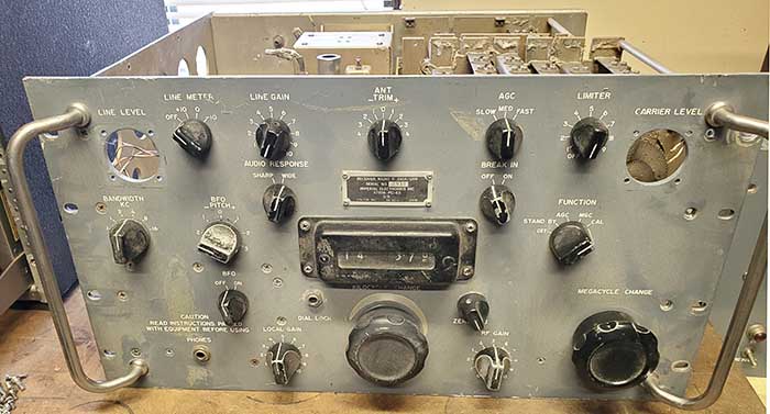
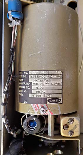
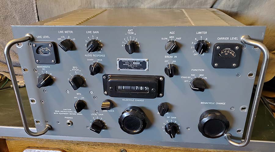
1963 - Teledyne Inc.
or Imperial
Electronics Inc. - Order
No.37856-PC-63 3,976 receivers (some
data plates show Imperial, others show Teledyne, who owned Imperial)
1963 - Stewart-Warner Corp. -
Order No.DA-36-039-SC-81547 (may have been for modules only)
1966 - Communications Systems
Inc.
- Order No.FR-11-022-C-4-26418 (this is an order number and may have been for modules only)
1967 - Electronic Assistance
Corp. - Order No.DAAB05-67-C0115 (some data plates have the
Order No.FR-36-039-N-6-00189(E) shown instead of the DAAB Order number)
10,717 receivers plus 151 consumer (rocket tag) receivers
1968 - Dittmore-Freimuth/EAC
- Order No.DAAB05-68-C-0040 215 receivers built by
Electronic Assistance Corp. for Dittmore-Freimuth
1984 - Fowler Industries -
Order No.N 00024-84-C-2027 5 receivers
NOTES:
"Order No." is what appears on the data plates of the receivers. Order
No. is often used interchangeably with "Contract No." although,
officially they probably don't mean exactly the same thing.
The first 1,027 R-390A receivers built by Collins will have long data
plates with 14214-PH-51-93 as the Order No. This Order No. was also used
for R-390, R391 and R-389 receivers and early Motorola R-390 receivers.
After the initial 1,027 receivers, Collins R-390A receivers have short
data plates with either 375-PH-54 or 08719-PH-55 Order Nos.
Shortly after Teledyne Inc. was formed, in June 1960, they purchased Amelco
Corp. (they had invested in Amelco's initial start-up.) Imperial Electronics was also an early
purchase by Teledyne.
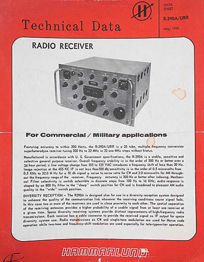
Electronic Assistance
Corporation owned Hammarlund in
the late-1960s and the 1970s. It's often erroneously reported that Hammarlund owned EAC but, confirmed
with a 1970 Hammarlund flyer advertising the R-390A, that plainly states at the
bottom that Hammarlund was a subsidiary of Electronic Assistance
Corporation. In the early-1960s, Hammarlund was owned by Guianini
Scientific Corp., at that time Hammarlund Mfg. was located in Mars Hill, NC.
See next section below for more details on the EAC/Hammarlund sales of R-390A
receivers.
Dittmore-Freimuth was a company located in Wisconsin that was primarily known
for working on government contracts producing mainly components like
telegraph keys, filters and later moving into sonar systems for the
Navy. Fowler Industries was supposedly a subsidiary of the Helena
Rubinstein Company. The five "newly built" R-390A were supposedly a
result of a ship rebuild/refitting that took place at a shipyard in
Louisiana. The rebuilder insisted on "new" equipment only and that
stipulation was taken literally (even though "unused-new in the crate"
R-390A receivers were still around at that time.) The contract went to
Fowler and the five receivers were built. Of the five, only one still
exists in complete original condition, a couple others are restored and
one or two have never been found. Supposedly the quality of the Fowler
R-390A receivers was noticeably inferior to the original contract R-390A
receivers.
There are a few other contractor companies that were
involved in producing R-390A receivers and modules but those listed produced the
greatest quantity of receivers with Electronic Assistance Corporation
building the largest number of R-390A receivers on a single contract at 10,717
and Motorola building the largest total quantity of R-390A receivers,
although requiring
three different Order Nos., ultimately producing 14,873 receivers.
It's generally believed that a combined total of at least 55,343
R-390A receivers were built by the various contractor companies.
Receiver quantities from: www.navy-radio.com |