|
UPDATE: June 29, 2022
- Well, here it is two and a half years later and I guess I've gotten
over my frustration with the R-389 VFO problem since I put the
R-389 back on the workbench. For the past couple of years I've been
watching for a spare 70H-1 PTO for sale - hah!,...none, of course! Also, watching the
sales of "parts set" R-389 receivers. I probably saw three or
four come up for sale in that time period. I've come to the conclusion that
there are no R-389 "parts sets" at least as far as sellers dealing in
Collins equipment think,...maybe Collins gear buyers too,...every piece
of junk is restorable. All R-389 receivers are being sold with the
caveat "I got this from an estate and don't know anything about it,..."
or, "For parts or restoration,..." or some other obvious obfuscation of
the actual condition of the receiver. However, even the worst condition,
most incomplete and obviously non-functional R-389 still seems to sell
for over $1500. Of course this is on eBay. Although, I do know of a
local ham that has two consecutive serial number R-389 receivers but
their actual electronic condition is unknown since the ham is more of a collector than anything else
and he's never powered-up either receiver (or almost anything else in
his collection.)
At the present time these two R-389s aren't for sale at any price. So, rather than
essentially pay a minimum of $1500 for a 70H-1 PTO, I've put my R-389 back on the bench to see what else I can come up
with for a long-lasting fix to the 70H-1 problem.
Since it's summertime, I decided to just skip LF and go to the AM-BC
band right off. I was surprised that after 2.5 years the R-389
powered-up without any issues other than some random noise that seemed
to disappear after about five minutes of operation. I connected an end-fed wire antenna of about
162ft length to the Unbalanced Antenna Input. As I tuned around, it
seemed like the AM-BC stations were pretty close to their correct
frequency. I checked the Carson City AM station on 1300kc and it was on
1310kc. KOH 780kc was on 785kc. KPLY 630kc was on 632.5kc. All three of
these AM-BC stations were pushing the CL meter up to 80db+ with the
clear BC frequencies reading about 10db on the CL meter. So, on the
500-1500kc band, the R-389 seemed pretty normal. Next, the 15-500kc
band. I tuned in WWVB 60kc on 61kc. NPM 21.5kc was on 21.5kc and
NML 25.2kc was on 25.2kc. Since the USN MSK stations are so close to
15kc and that is the mechanical calibration point of 470kc from the
70H-1VFO it's normal for these stations to be very close to "on
frequency." As the tuning approaches past the middle of the VFO span and
higher then the error becomes more apparent. One can extrapolate that
the 10kc error on 1300kc would probably be a 5kc error at 400kc in the
15-500kc band, which was very close to what I was experiencing a couple
of years ago when the VFO was "on frequency." More accurate
testing using a RF Signal Generator showed that maximum error was about
8.5kc at the top of 15-500kc and about 17kc at the top of 500-1500kc.
This was very close to what I was experiencing a couple of years ago when
the VFO was "on frequency" or as close as I could get it. Next testing will be
operation of the R-389 until the VFO again goes "off frequency." I'm
really surprised that it's back "on frequency" now because when I stored
it away it was reading 25kc high at 326kc (DC 326kc was tuned in at
352kc) in the "failure mode" and the receiver's current condition implies
that the VFO problem "corrected itself" just setting around for two
years. That's pretty hard to believe, unless the problem is entirely
thermally induced and possibly mechanical in nature. This could be a
cracked ferrite core or it could be something as simple as a bad solder
joint. More testing,...
July 1, 2022 - I've been running the R-389 several times
during each day trying to induce the VFO frequency "jump." So far,
there's been no change and the receiver seems to operate very well.
However, today I noticed something different that might be VFO-related.
The R-389 had been operating for about a half-hour and was tuned to WWVB.
I was in the adjacent ham shack room but could still hear the R-389. I
thought I heard the audio tone caused by the heterodyne BFO changing
randomly. The tone change was very slight, maybe a few hertz, so I
thought it might be just a "hearing anomaly" caused by my location in the other room. But, carefully
listening at the R-389 and the heterodyne tone was definitely changing slightly.
Only a few hertz random change would probably go unnoticed but since the VFO is certainly a likely candidate for the cause, I will look into this
indication and possibly use the DFC to verify that the VFO is what is
changing frequency and if it might be related to the f-jump problem.
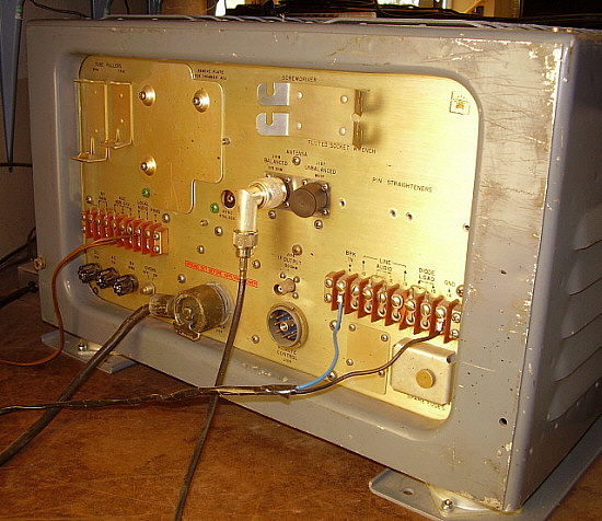
July 2, 2022 - R-389 on
for 45 minutes before the random few hertz changes were noted. Since the
initial problem of VFO frequency jumping always had occurred when the
receiver was installed in the CY-979A cabinet, I wondered if heat might
be involved. I've been running these tests with the receiver out of the
cabinet and with the top and bottom covers off. To further reduce the
heat, I installed a line bucking transformer into the hook-up to reduce
the AC line voltage from 124vac down to the specified 115vac. Although
the B+ is electronically regulated at +180vdc, the series-parallel tube
heaters aren't. It might help but probably not. Incidentally, the
CY-979A is now home for the Arvin Industries R-725 receiver, so I won't
be putting the R-389 into a cabinet in the future (that changed July
3, 2024 with a third CV-979 showing up.) It's probably not a
good idea anyway since the tremendous heat from the electronic voltage
regulator seems sort of "trapped" when the R-389 was housed in
the CY-979A. Same
goes for installing the top and bottom covers in that it seems to really
trap the heat on the left side of the receiver. Also, I placed spacers
under the main frame of the R-389 to elevate it about 1.5" to allow
better air flow underneath the receiver.
July 5, 2022 - Continued
daily operation for about 30 to 60 minutes with no changes. The
few hertz frequency instability was traced to the BFO. A signal carrier was found
on LF at around 130kc. Using the BFO, the heterodyne produced was very
unstable varying every few seconds by a few hertz but always returning
to the set frequency. I then coupled the HP 606B RF signal generator to
the receiver to heterodyne with the 130kc carrier. Of course, the
difference is that the BFO heterodynes at 455kc while this setup
heterodynes at 130kc. The R-389 BFO was turned off. The carrier plus
heterodyne producing signal didn't vary at all. Both were solid. This isn't the VFO frequency jump problem but it's something else that has turned up.
First replace the BFO tube but that probably won't help - and it
didn't. I'll have to use a tube extender for the BFO tube to access
the pins to see what is really happening.
July 12, 2022 - Slight
screen voltage changes on BFO seem to indicate that the bypass capacitor
is probably leaking (also, screen voltage is about 11vdc lower than
expected at +74vdc instead of +85vdc.) Minor problem that can wait.
Since the R-389 won't go into VFO failure I decided to go ahead and move
it to a listening position where I can power it up from time to time. It
seems typical that once I had it moved to its new location - it would
fail! This was different though in that no signals could be tuned in,
just lots of noise. Turning the receiver on its side I just touched the
VFO tube and all signals returned. I pulled the VFO and BFO tubes and
swapped their positions. Also swapped the 3TF7 with another ballast
tube. The receiver seemed to be back to normal. I'll keep an eye on the
VFO tube socket as a possible contact problem. But, for now, I'm just
going to listen to R-389 probably about once a week or so and see how
long the "self-healing" VFO lasts.
July 22, 2022 - Tests okay.
Aug 1, 2022 - Tests okay.
Aug 17, 2022 - Tests okay.
Aug 31, 2022 - Tests okay. With this test, I checked
operation on the 500kc to 1500kc band tuning in several AM-BC stations -
all close to "on frequency." On the 15kc to 500kc band, I tuned in NPM
21kc, NAA 24kc and NLK 24.8kc along with the normal reception test
signal from WWVB on 60kc. All stations were close to frequency on both
bands. Incidentally, KKOH on 780kc drove the CL meter up to +95db using
160' wire antenna.
Sept 24, 2022 - The R-389
has been setting, unused due to some station reorganization. So, prior
to this test, the R-389 had not been powered up for about three and a
half weeks. It was then moved to a different desk and moved from side to
side and back and forth until I was satisfied with its position on the
desk. At this time, it was connected to the wire antenna and powered up.
The tuning was where I had left it on 780kc and, within a short time,
KKOH came in with a +90db signal. I tuned to the lower range (15kc to
500kc) and tuned in WWVB at 60kc, coming in with a strong signal. I left
the R-389 powered up for about 30 minutes with no problems encountered.
Oct 12, 2022 - I used the
R-389 a few times now in its new location. The receiver isn't in the
CV-979A cabinet and both top and bottom covers are removed. Also, the
receiver is slightly elevated to induce more cooling. So far, no
problems. Other Tests in Oct
- okay.
Failure Nov 2, 2022 - VFO f
jump about 20kc high on low band. Interestingly, I tried a heat gun to
warm up the VFO but only for a minute or two. Then I turned on the oven.
After a minute or two, the VFO instantly changed back to the correct
frequency. It wasn't a slow drift, it was an instant change as soon as
the VFO had gotten warm enough. All through the summer, the VFO had been
working fine. Within the last couple of weeks, with Fall, the
temperature has significantly dropped. Last check in the ham shack was
62F. Not cold but a lot cooler than in the summer when it's usually
minimum 75F in the ham shack. There are only a few parts in the VFO that
could be affected by temperature, unfortunately the ferrite core could
be one of them. More testing required to see if the oven temp instigates
the frequency jump every time.
Test Nov 4, 2022 - Cold
start off frequency 20kc. Turned oven on. 4 minutes later, the frequency
jumped down 20kc to the correct frequency. Next test will see what
happens if the oven is left on for 30 minutes which is the normal
listening time period.
Test July 2, 2024 - It's
been a while. Since it's summer and the room temp upstairs is running
about 78F, I thought I'd try the R-389. The VFO oven was turned ON. I
had KKOH 780kc tuned at 781kc. The receiver operated correctly for about
15 minutes and then jumped frequency about 40kc (20kc on 15-500kc
Range.) Later in the afternoon, with the oven turned OFF, I powered up the
R-389. It came up on frequency at 781kc for KKOH. I let the receiver run
for about 15 minutes and no f change occurred. This frequency jump
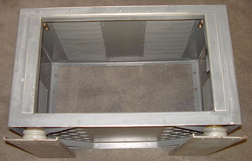
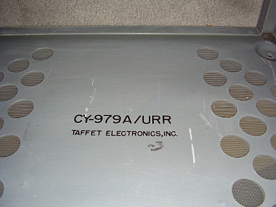
certainly appears to be temperature related. Incidentally, I was given
another CV-979A cabinet. It had been left outside under a carport in
Yerington, Nevada for years. The paint was sun-faded and a little bit
oxidized from the weather exposure, but otherwise, the cabinet
was physically straight with no dents and overall in pretty nice condition. I cleaned it up and
polished the stainless steel inside slides. I removed two wooden skids
that were bolted to the bottom of the regular steel skids. The wood was
deteriorated and its removal improved the overall appearance of
the cabinet. So, I've installed the R-389 into this CV-979A (contractor
Barker & Williamson) since I don't really think it makes very much
difference in the VFO versus heat operation. I did leave the top and
bottom covers off of the receiver.
UPDATE: Mar 1, 2026 -
I've been testing the R-389 about once a month for the past
year and a half. I start at WWVB 60kc, tune down to the USN MSK Sub Comm stations
from 25kc down to 19kc. I then go down to 15.6kc to see if I can pick-up
the upper Russian RSDN-20 Alpha Nav signal (these are powerful
signals that are located in Central Russia. The RSDN-20 power level is
around 500KW.) Then I tune up to Loran-E Master Station "M" in
Fallon, Nevada on 100kc,...400KW only 50 miles away,...what a signal! I tune to 162kc to see if I can pick-up
ALS162, the
time signal out of France that runs 800KW. I usually will test if the
NDB MOG
402kc can be received (MOG is the closest working NDB at 150 miles
distance but it only runs 50 watts so I usually can't receive it during the
day.) Then I switch to the 500kc to 1500kc range and tune in a few AM-BC
stations. Then I return to the 15kc-500kc range and tune back to WWVB
60kc. The complete test takes about 15 minutes. So far, the R-389 has
worked correctly every time it has been tested,...but, it could fail on
the next testing,...one never knows. |