 |
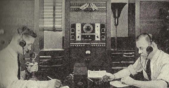
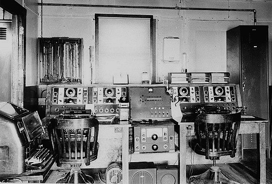
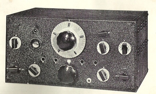
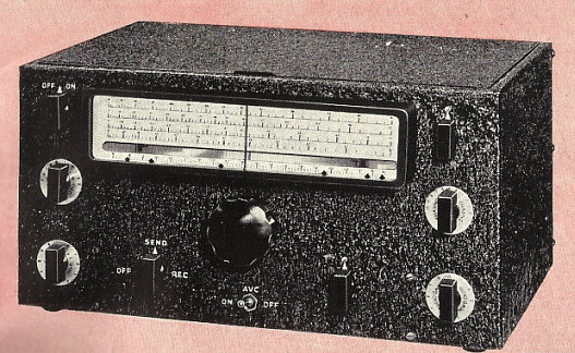
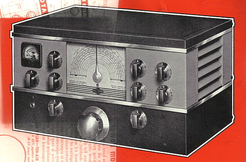
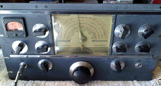
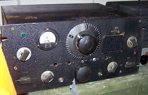
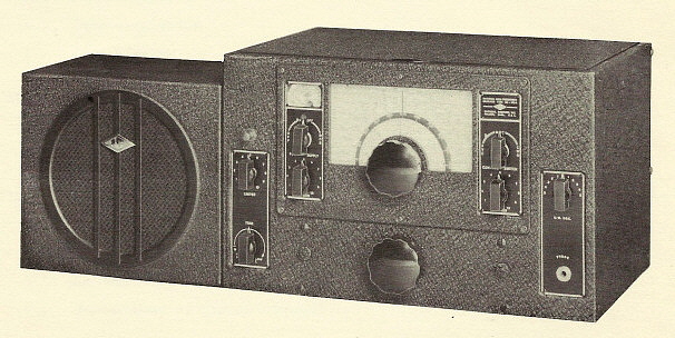
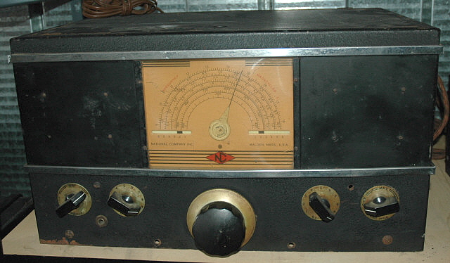
photo left: The Air-Ground Radio
Station at Kansas City AP around 1936 showing the use of the
stock NC-100 receiver at the time before the
availability of the RCD Communication Receiver, the
first of the National "Airway Receivers." - from Sterling's Radio
Manual 3rd Ed. |
|
The continuing improvement of airport to airplane radio
communications along with improved radio-based airway navigation equipment
had started in 1926 and was
on-going through the 1930s. At the time, the Department of Commerce and
the Bureau of Air Commerce were in charge of airports, airport
communication and air navigation. The first National receiver
specifically for airport communications was the
RHM, a superheterodyne (National's first)
supplied in 1932. The RHM evolved into the
AGS receiver that was also
used at some airport installations. Additionally, the
AGS evolved in the
RHP, RHQ and the
AGU - all based on the
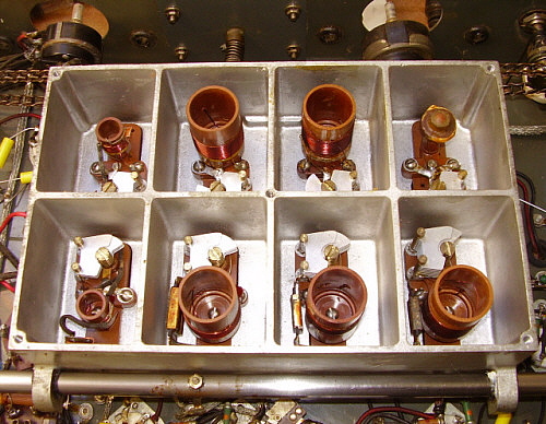
RHM circuit but using ganged,
plug-in coils rather than individual plug-in coils (a set of three coils
were required for
each frequency tuning range.)
From 1935 up to around 1937, the HRO was favored by
many airlines but the HRO had numerous accessories that required
additional storage be provided. Each HRO came equipped with four coil sets, a
separate power supply and a loud speaker. Custom installations usually
were able to integrate the HRO
and its accessories into the airport communications equipment racks.
|
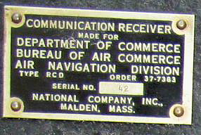 |
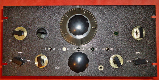
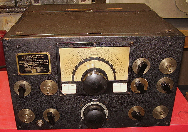
photo left:
This is the data plate used on the first of the Airport
receivers, the RCD, from 1937. Note that the RCD is
specified as a "Communication Receiver" only. The Bureau
of Air Commerce - Air Navigation Division was under the
Department of Commerce in 1937. Note that this data
plate is attached to the front panel with drive screws
(pins) rather than standard screws.
photo by:
Warren Anderson |
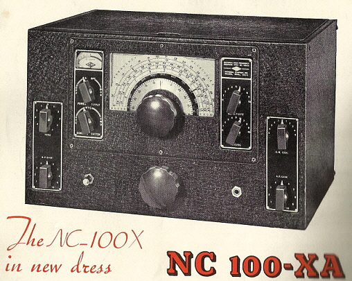
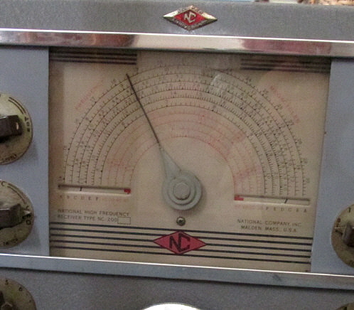
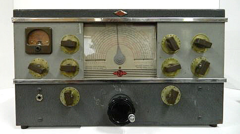
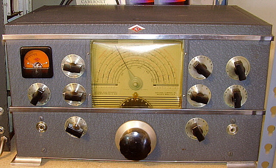
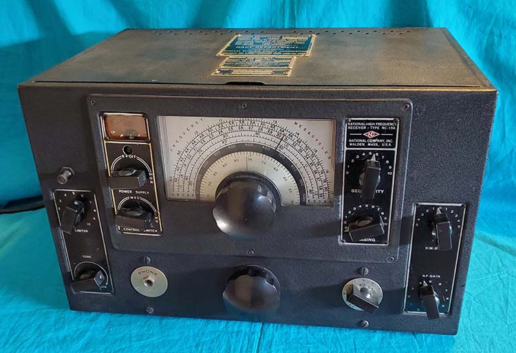
Starting in 1936, National began supplying the standard
NC-100 (with
its art deco front panel and no modifications) to various airports (see
photo above of the KC AP in 1936.) It's
likely that the "commercial" NC-100 versions were also supplied to some
airports in 1936.
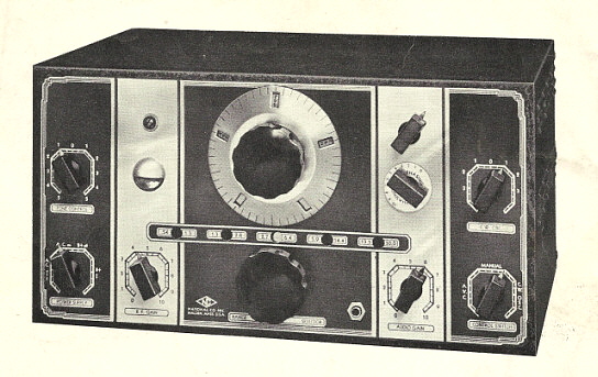
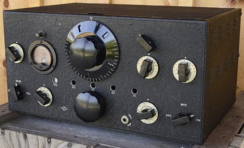
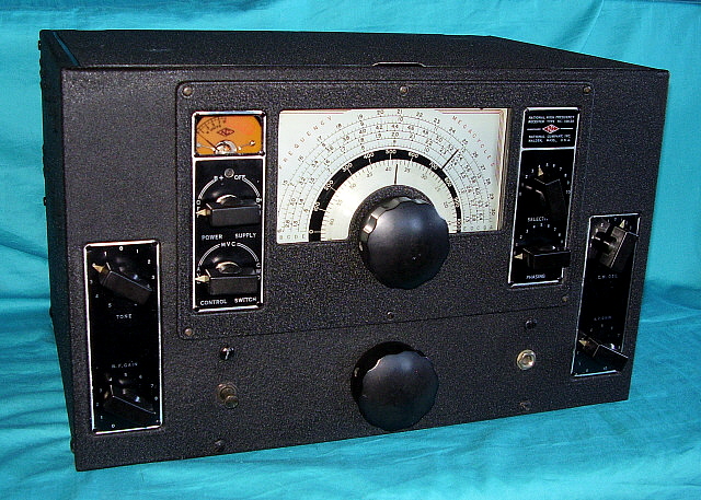
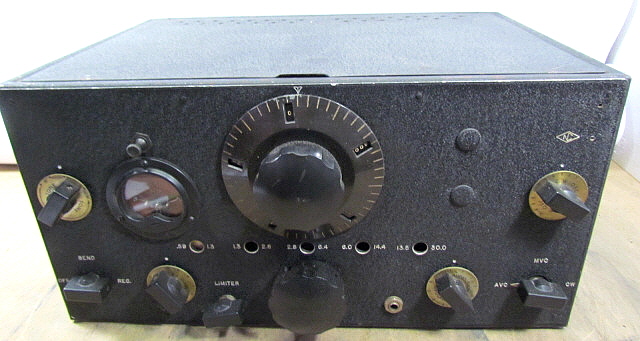
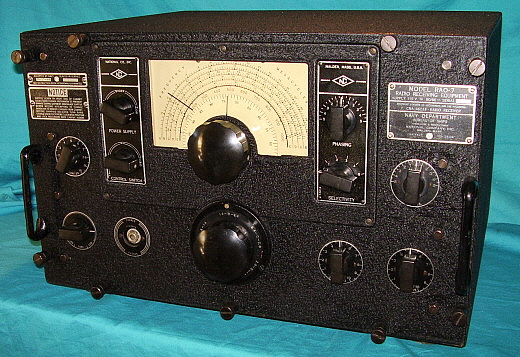
Starting in 1937, National began supplying somewhat modified
NC-100
receivers for use at airports for tower communications to local aircraft and for
aeronautical communications which was the "ground to air" radio
communication that supplied non-local aircraft with weather,
navigational information and messages. There was also an aeronautical
point-to-point communication system that was CW only. National's first "modified for
airport use" NC-100-based receiver, the
RCD, designated as
"Communication Receiver." The
RCD was essentially a rack
mounted
NC-100X with a frequency coverage that was altered to remove the AM BC
coils and replace them with coils to cover 200kc to 400kc. The remaining
catacomb coils were not changed and allowed 1.3mc to 30mc coverage in
four tuning ranges. These initial
NC-100-based airport receivers used a 3/16" thick aluminum panel that was black
wrinkle finished along with retaining the Crystal Filter and the cathode ray tuning indicator.
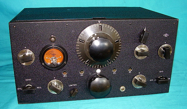
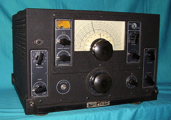
The RCE receiver that followed had several improvements which became standard for
National Airport receivers although the
RCE was still built for
the DOC-BAC. The RCE removed the eye tube and the crystal filter used by
the RCD and added a squelch
control.
|
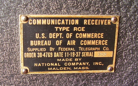
photo above: Data plate from the RCE SN:
302
receiver dated 11-19-37 |
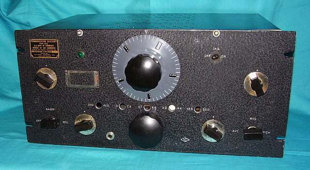
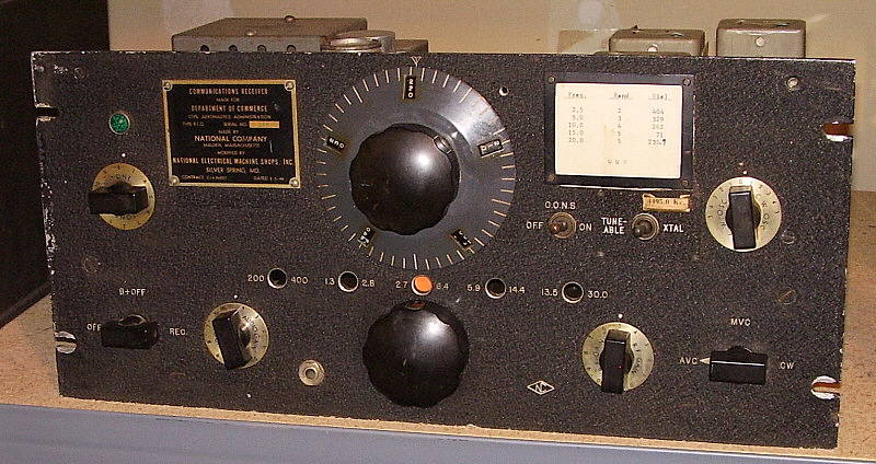
By 1938, the
U.S. Civil Aeronautics Authority, the CAA, had taken over the
responsibility for airports and air communications. By this time, the
Airport receivers had even more additional circuitry added to further
adapt them to airport communication requirements. The CAA designated
these newer receivers as "Airway Communication Receiver" as shown in the
RCF-2 data plate shown in the photo to the upper-right.
The RCF designation was
probably assigned to another piece of equipment (probably USN,) thus the
suffix "-2" added to the RCF-2
receiver.
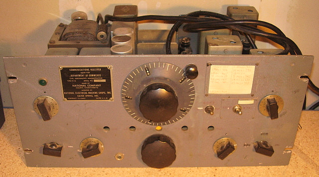
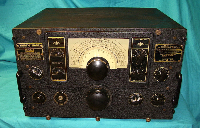
The standard CAA Airport versions used 12 tubes, had no Crystal Filter
and no carrier level indicator. The audio output was changed from Push
Pull tubes operating an output transformer mounted on the
electro-dynamic speaker of the "civilian" models to a single audio tube
with an output transformer internal to the receiver which allowed PM
speakers to be used. The power supply was slightly modified to include an extra filter
choke since the field coil of the electrodynamic speaker wasn't
available for that function. The typical CAA receiver
used a 3/16" thick aluminum front panel painted black
wrinkle finish with engraved nomenclature. This description also applied to the earlier
RCE receiver
built for the DOC-BAC but not for the earlier
RCD. >>>
|
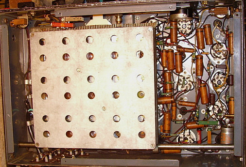
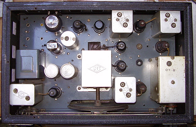
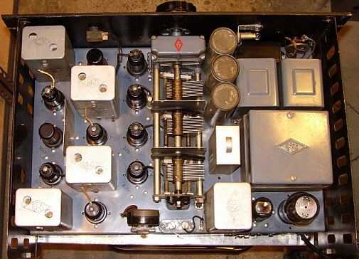
>>> A gray painted PW-D was standard for all Airway
receivers. The IF was usually 457kc. Later
versions will have a two-position selectivity control and, later still, a crystal-controlled fixed-frequency
function. For fixed-frequency operation, the receiver had to be tuned
near the crystal frequency minus the IF for the RF amplifier stage and
the Mixer to be tuned correctly. If the fixed-frequency desired was, for
example, 4495kc, then the crystal required was 4495kc + 457kc = 4952kc
crystal frequency. This put the fixed-frequency LO operating higher than
the tuned frequency which is the normal configuration. Most CAA
early versions will have a squelch added
that is referred to as the Interchannel Noise Suppressor, or
I.N.S., which was activated by a front panel toggle switch. The I.N.S.
circuit used a 6J7 tube that was operated from the 6J7 AVC tube and when
the AVC bias voltage was being driven negative by lack of a signal, the
I.N.S. tube would bias off the 1st AF Amplifier tube (6C5) which reduced
the audio output to a very low level. Although the I.N.S. could be
adjusted to "full squelch," National recommended that the I.N.S
"suppression" be set
to allow a very slight background noise to be just audible and then when
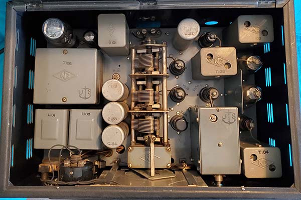
a desired signal was received the I.N.S. would provide a "normal" audio level. The I.N.S.
is adjusted with the two potentiometers that are mounted at the rear of
the chassis directly behind the tuning condenser. Typically, the
eye-tube of the standard NC-100 or other type of carrier level measuring
device was not used on the CAA receivers but at least one RCF-2 example
has turned up with a National S-meter that appears to be a factory
installation.
|
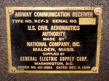 |
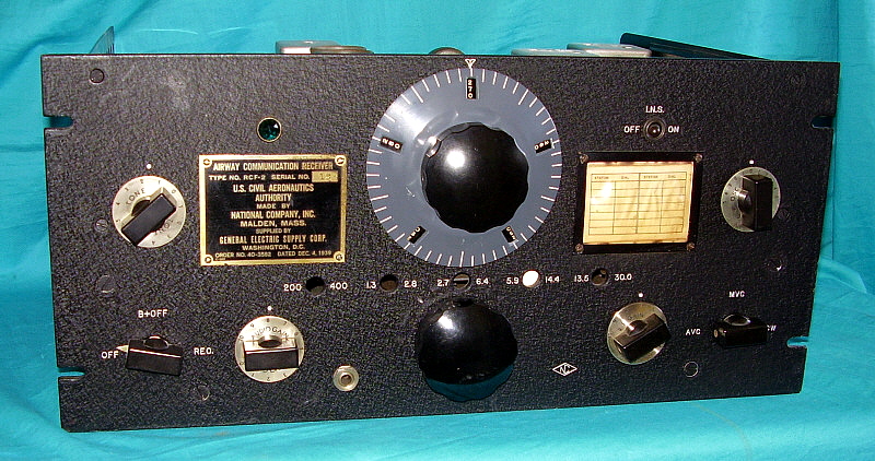
photo left: A close-up of the data plate on the RCF-2 sn 13 showing
that National specified the RCF-2 as an "Airway Communication Receiver."
The receiver was built the for General Electric Supply Corp. of
Washington, D.C. to supply to the CAA. Note the contract date of
December 4, 1939. |
The audio output was rolled off at 3000 Hz by using
an in-circuit audio filter that is between the output of the first AF
amp and the input of the 6V6 audio output tube. National felt that the
necessary voice characteristics that affect intelligibility are all
contained in the audio frequencies below 3000 Hz. As with military
versions of National receivers, the P-P audio was replaced with a
single-ended audio output tube and an internal output transformer
provided 600 Z ohm output along
with a Hi-Z audio output (20K Z ohm.) The phone jack on the front panel
is a 600 Z ohm output. Some versions had an internal relay that operated
on 6vdc (supplied externally) to disconnect the speaker but not affect
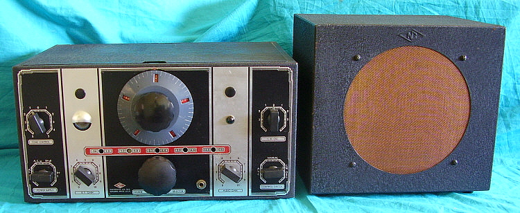
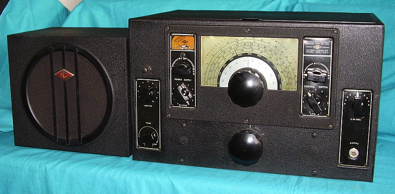
the headset output. A single
loud speaker was supplied and also a rack mounted dual speaker assembly
was sometimes supplied. Some versions also had remote control available
for RF and AF Gain functions. Some versions had a dual fused AC line
input while others have a HI AC or LO AC primary on the power
transformer which is selected by which fuse clips are used in a dual
fuse holder. Some receivers had both. All versions used oil-filled paper dielectric filter
capacitors and have two filter chokes.
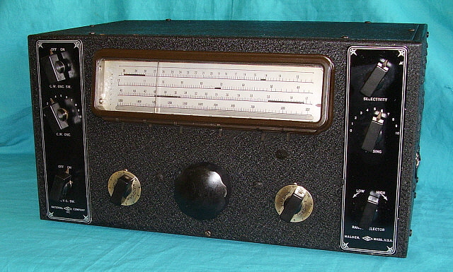
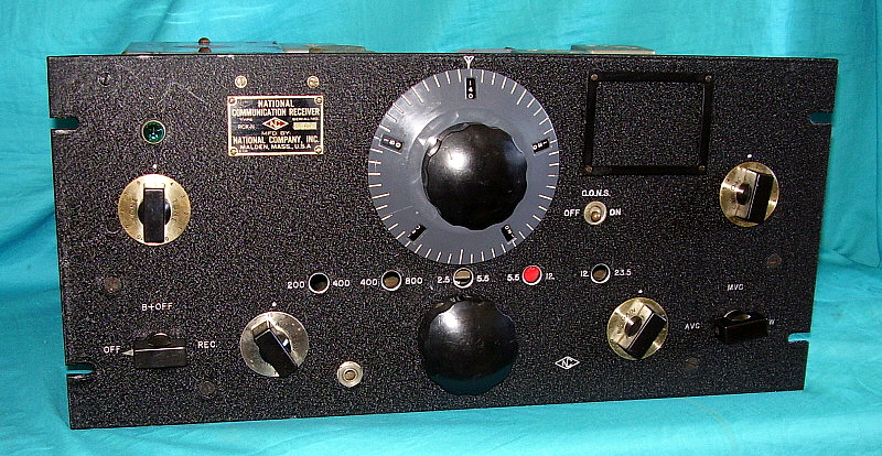
With the RCK-N versions, the
I.N.S. circuit was replaced with the C.O.N.S. circuit, or Carrier
Operated Noise Suppression. This was an
improvement that operated a relay that silenced the receiver if no
carrier was present. Additionally, the pilot lamp would illuminate when
a carrier was present. The RCK-N
was built for the U.S. Navy during WWII. It covers 200kc to 800kc in two
bands and 2.5mc to 23.5mc in the other three bands. The IF on the RCK-N
was changed from the typical 457kc to a higher frequency of 1560kc to
allow complete tuning from 200kc up to 800kc. The designation
RCK was also used for a piece
of VHF four channel receiver used by the USN, thus the suffix "-N" to
specifically identify this Airway receiver.
The RCL added a switch that
allowed selecting either a Broad or Sharp selectivity. Later, it was
found that the selection process slightly changed the IF center
frequency. When crystal-controlled, fixed-frequency operation was
installed the Broad-Sharp switch was removed.
|
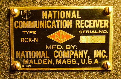
photo above: Data plate from RCK-N
SN:182 from the WWII-era built for the USN |
After WWII, many of the earlier version receivers (RCL
and RCK versions) were modified
into the RCP and the
RCQ versions. The
modifications were to add a selectable crystal-controlled
fixed-frequency operation. These receivers also had modifications to the
AVC and the addition of a series noise limiter (that was always on.)
Also, the Broad-Sharp selectivity switch was removed due to IF
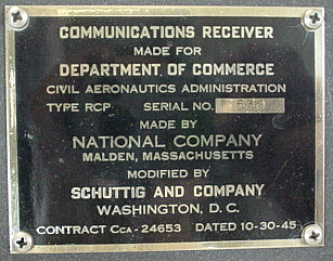
instability problems. RCP modifications date
from around 1945 and the rework was done by Schuttig & Company. The
RCQ modifications date from 1948 and the rework performed by National
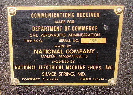
Electrical Machine Shops, Inc. (NEMS.) The last of the National Airport Receivers was the
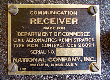
RCR dating from 1948. It was
essentially an unmodified NC-240CS from the late-forties.
Since Airport communications and electronics, in general, were
evolving rapidly in the early-1950s, it's likely that the life of most
of the National Airport and Airway receiver didn't last past the
late-1950s. Many were repurposed into other functions, perhaps at
airports and maybe other locations. Eventually, most were sold off to
surplus vendors or scrap dealers. |