Radio Boulevard
Western Historic Radio Museum
 

NATIONAL COMPANY, INC.


"MOVING COIL" COMMUNICATION RECEIVERS


Includes NC-100, NC-101X, NC-80X, NC-81X, NC-100A family,
 NC-200, NC-240CS, NC-240D
Dept of Commerce & CAA Airway Communication Receivers
Military Versions - RAO family, RBH, NC-100ASD, R-115, R-116

by: Henry Rogers WA7YBS-WHRM


     PART 1 - History of the Moving Coil Receivers, Details on production models 1936 to 1948, Airport Receivers, US Navy models, US Army models, USCG models.


     PART 2 - Serial Numbers & Log, Production Engineering Changes, Catacomb details, PW Gearbox, PW-D, Tubes, Power Transformer info, Speakers


     PART 3 - Restoration Write-ups: NC-200 Silver Anniversary, NC-100XA,
NC-100ASD
 

     PART 4 - Restoration Write-ups: RCE Airport Receiver, NC-101X, NC-80X

PART 2

Serial Numbering on the NC-100 Series

Serial Number Formats Used - Serial numbers on early NC-100 receivers appear to be the same kind of format used on other National receivers at the time. This consists of a letter that identifies the production run and a number that identifies the specific receiver within that production run. When the NC-100 was introduced in 1936, the HRO receiver was still using serial numbers that consisted of a letter prefix followed by a number suffix. Probably to keep the two receiver type serial number formats obviously separate, the NC-100 serial numbers began with a number prefix followed by a letter suffix (the letter identifies the specific production run.) From the serial numbers reported so far, it appears that the NC-100 series serial numbers begin with the "D" suffix to identify the first production run. Interestingly, the HRO first production run also used the prefix "D" to identify its first production run. By 1938, the HRO had used all of the letter prefix serial numbers and then began to use a letter suffix combination, like the NC-100 had been using. 

It appears that all NC-100 series serial numbers are sequential in their assignment within the particular production run and those production run letters are also sequential starting with run "D" in 1936. It also appears that most production runs had quantities of around 350 to maybe 400 receivers within them. From the serial numbers reported, it appears that all NC-100 Series receivers use a letter suffix in the serial number with the exception of the WWII military versions.

The NC-80 receivers have their serial numbers stamped on the rear panel of the cabinet at the lower-center just below the headphone jack opening. Since the cabinet was painted black wrinkle after the stamping, the serial numbers are sometimes difficult to see. The NC-80 receivers use a different format with a letter prefix followed by numbers. From the one reported NC-80X serial number, it appears that National used the prefix letters not used by the HRO series (A, B & C.) Since the production was low on these receivers, it's possible that all NC-80 series receivers used the "C" prefix (since the reported serial number is C-745,) although this is just speculation.

The NC-200 serial numbers use a letter prefix followed by up to three numbers. It appears that production runs C, D and E comprise the production of NC-200 receivers. It seems unlikely that the NC-80X series, that also used "C" prefix serial numbers, shared serial number prefixes with the NC-200 since the former was produced from 1937 up to 1939 and the latter was introduced in late-1940. Since both model receivers used the same serial numbers, one has to assume that National used the receiver model and its serial number for identification.    >>>

>>>   During WWII, serial number formats vary somewhat but usually follow the letter prefix format. Often times, the serial number is only found on the particular receiver's data plate. Normally, if the serial number is on a data plate it will just be a number with no letters. Most NC-100ASD serial numbers use only numbers that are stamped into the chassis between the 6C8 and the 6F8 tubes but there are exceptions. WWII must have been a hectic time at the National plant and this resulted in some mistakes and certainly inconsistencies in serial numbers and serial number formats. One could almost say "expect just about anything" when it comes to formats, locations or even "lack of" serial numbers used on National's WWII production. 

Early post-WWII serial numbers are still letter prefix format using the prefix F for the production run in 1946. It seems likely from the serial numbers reported so far that run F began after WWII ended. Sometime in 1946, National changed the serial number format to a seven digit serial number that consists of a three digit production run ID followed by a space that is then followed by a four digit number that identifies the receiver. So far, runs 169 and 183 appear to be for the late NC-240D receivers.
 

WHRM Serial Number Log for NC-100 Series Receivers - In an effort to see what kind of serial numbering National used on the NC-100 Series, WHRM is starting up another serial number log. These logs are very effective at providing production quantity information and year of manufacture information after a fairly large quantity of serial numbers have been collected. When providing a NC-100 Series serial number for our log, please be sure to let me know the model of the receiver that the serial number belongs to. Also, note any characteristics that will help in determining the manufacturing year. Also, note any unusual production changes or professionally installed modifications. See the log below for some of the identifiers and details we're looking for.

After enough numbers have been collected it may be possible to date the year of manufacture from the serial number used. Please send your serial numbers from any NC-100, NC-100X, NC-101X, NC-80X, NC-81X, NC-100A, NC-100XA, NC-101XA, NC-200, NC-240D, NC-240CS, RAO, RBH, NC-100ASD and any Airway Communication Receivers to this e-mail:

     WHRM: NC-100 Series Serial Number LOG info
 

Serial Number Locations: Generally, on the early versions of the receivers the serial number is stamped into the chassis top usually in front of the antenna terminal insulator between the rear of the tuning condenser and the front of the antenna terminal insulator. The serial number will appear upside down if you look at it from the front of the receiver with the lid lifted. See the first photo to the right for NC-100 Series SN location as viewed from rear of chassis. When the larger rear mounting flange was used on the tuning condenser, the serial number was moved closer to the antenna terminal insulator and more towards the audio output tubes. See photo far right for location on the NC-200 Series receivers.

Sometimes serial numbers appear only on the data plate of the specific receiver. This mainly applies to the Airport receivers since their serial numbers are only on data plate mounted on the front panel.    >>>


photo above: SN location on NC-100, NC-101X, NC-100A and NC-101XA (pre-WWII receivers.) SN 40X is an NC-101X. This shows the later polystyrene Ant-Gnd insulator.


photo above: SN location on the NC-200 receiver showing that the placement of the stamped SN has been moved because of the larger mounting flange used on the newer tuning condensers.


>>>   During WWII serial number locations vary. The NC-100ASD didn't use a data plate but does have a three-digit serial number stamped into the chassis between the 6C8 tube and the 6F8 tube.

Generally, the RAO and other WWII US Navy receivers will have a SN located on the data plate and another different serial number stamped in the chassis between the 6C8G tube and the 6F8G tube. These two numbers never match (they aren't even the same format) because the data plate serial number was assigned and stamped when the fully assembled receiver was used to fulfill a USN contract. The chassis serial number was assigned and stamped during production (before the receiver was assembled.) The data plate serial numbers aren't sequential and the total build quantity of each National production run is unknown so there isn't a correlation that can be made between the data plate serial number and the chassis serial number on many of the National WWII receivers and especially on the RAO receivers. Wells Gardner RAO versions don't have a chassis serial number.

Post-war, with the NC-240 series, the serial number is stamped on the top of the chassis on the right side edge midway back. Some early NC-240D serial numbers are located on the top of the chassis at the left rear corner. Note that with the later NC-240D, the serial number is a seven digit sequence that incorporates the production run identification into the first three digits and the receiver identification into the last four digits.

NC-100 - 334-D (deco pnl), 5-E, 341-F (rack mount, no alum overlay on panel, eye tube), 531-G (deco pnl), 638-G (deco pnl), 309-Y (black wrnkl pnl, NL),

NC-100X - 217-D (reworked from NC-100 at Nat'l), 227-D, 257-D, 435-D (has original rack mounting brackets), 48-E (deco pnl), 216-E,  253-E, 99-J,

NC-101X - 78-D(? - ham mod'd with meter), 62-E(mod'd at Nat. with S-mtr), 147-F (eye), 217-F (eye),
53-G (Nat. white scale S-mtr - upgrade?), 181-G (eye), 209-G (mtr&NL-upgrade?) 365-G (S-meter - upgrade?), 490-G (eye), 541-G (eye), 247-J (S-mtr), 254-J (eye), 130-M (S-mtr), 101-N (white scale S-mtr), 141-N (white scale S-mtr),184-N (S-meter), 211-N (yellow scale S-mtr), 40-X (yellow scale S-mtr, Noise Limiter), 162-Y (yellow scale S-mtr, NL)
 

NC-100A - 145-T,

NC-100XA - 58-R (no NL), 99-X, B-943(NL),

NC-101XA -


NC-80X, NC-81X -  C-73 (80XB-battery op), C-197 (81X), C-745 (80X),


NC-200 - C-33 (SA), C-78 (SA), C-265(CS), C-536(SA), C-599(SA), C-859, C-877(SA), C-951, D-327, D-388(SA), D-499(SA), D-632(SA), D-639(SA), D-700(non-SA, parts set), D-716(non-SA), E-39


? = conflicting or unexpected data      

mod'd = "Nat." is National rework, "ham" is "hamster mods"

NC-240CS, NC-240D -  F-104(240CS), F-478 (240D), 168 0417(240D), 169 0061(240D), 183 0045(240D),
183 0080(240D), 183 0145 (240D), 183 0326 (240D),


RAO (NC-120) - 1064/na (RAO-3), 1412/na (RAO-3), 10/H720 (RAO-7), nodp/J444 (RAO-7), 1642/J944 (RAO-7), nodp/K155 (RAO-7),

RBH (NC-156) - 840 (RBH),

NC-100ASD - 194, 402, 426, 931, 948, A49**, A578**,

R-115, R-116 - 46(R-116), 103 (R-116),


Airway (Airport) Receivers - 15 (RCD), 40 (RCD), 42 (RCD), 101(RCD), 288 (RCE),
302 (RCE), 234 (RCF), 13 (RCF-2), 182 (RCK-N), 221 (RCK-N), 272 (RCP), 242 (RCQ),
288 (RCQ), 17 (RCR)

Custom AP Rcvrs - 531-G (NC-100 mod'd .2-.4mc on highest range [range A,] separate PS)


RAO = Data Plate SN/Chassis Stamped SN - numerical on data plate, letter prefix + number on chassis

SA = Silver Anniversary NC-200             **Confirmed SN for unexpected data

nodp = non-original data plate                  na = not available or unknown (W-G RAO have no chassis SN)


Production and Engineering Changes

1936

NC-100 and NC-100X introduced in August 1936

The Art Deco Panel - Aluminum sheet metal overlay for front panel is silk screened in black and red along with silver - used on both NC-100 and NC-100X, commonly referred to as the "Art Deco Panel." This panel was only used from the initial run-D up through run-G on the NC-100 and NC-100X. A black wrinkle finish overlay replaced the Art Deco panel and the eye tube was integrated in the same manner as the NC-101X. The PW-D likely would have also been changed to the black with black number dial, the same as the NC-101X. This change probably happened during or just after run-G. Certainly, by run-J, the S-meter replaced the eye-tube and then, at the very latest, the Art Deco panel was gone for good. It was certainly not used after the replacement of the eye-tube with the S-meter (run-J or mid-1937.) The Art Deco panel was replaced for a couple of reasons. First, it was delicate and scratched very easily. Excessive rubbing would easily wear through all of the silk-screen artwork and would also wear the matte silver finish. The second reason was as an expense reduction by the consolidation of parts. The Art Deco panel was unique to the NC-100 and NC-100X and certainly the process to produce the panel (or have it produced) was more expensive than a black wrinkle paint job. It was much easier and less expensive for National to start using the NC-101X black wrinkle overlay with these types of panels which were then usable on three types of receivers.

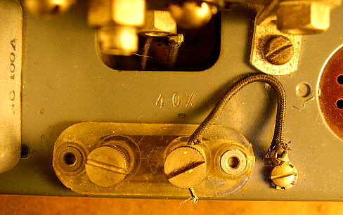
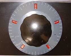
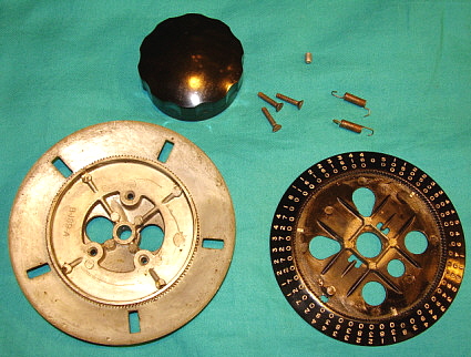
The PW-D - The initial PW-D micrometer dial used on early receivers was bluish-gray on the Index Dial and red with white numbers on the Number Dial, used on the NC-100 and possibly the very early versions of the NC-100X. Slight variations in PW-D paint color might be due to color variations in different paint mixes or due to different aging characteristics on specific PW-D dials. However, many PW-D dials were replaced over the years by owners and careless restorers so originality becomes uncertain. Generally, very early NC-100 receivers will have the bluish-gray Index Dial and red with white numerals Number dial. The NC-100X will usually have a light-gray Index dial with a black number dial with white numerals. There may be exceptions to this but, from examples seen, this PW-D difference between the NC-100 and the NC-100X seems to be consistent. Photo of 638-G (eBay) had deco panel and light gray PW-D with black number dial with white numerals - looked original. Also, NC-100X sn:48E, an original example, has a gray Index dial with a black Number dial. I don't have any data collected on whether the red number dial was used in the PW-D for the NC-100 past the first production run. Please report any NC-100 receivers in the E, F or G runs that have been found with original red number dial PW-D.

Chassis is painted gray on both NC-100 and NC-100X

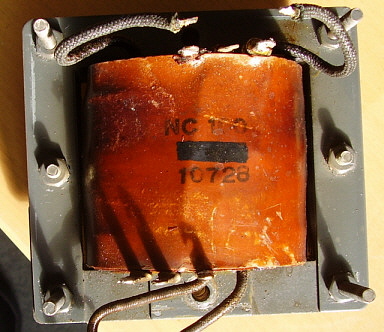
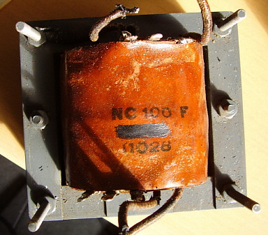
Power transformer top cover has four large ventilation holes

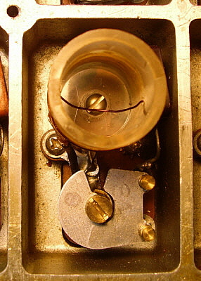
6E5 cathode ray tuning eye tube is used

Rack mount versions will not have aluminum overlay, panel is 3/16" aluminum with engraved markings, black wrinkle finish, eye tube used. Some versions may have single-ended audio output. Some rack mounted versions will use National-supplied rack mounting brackets that mount to the sides of the standard NC-100 table cabinet.

The first NC-100 and NC-100X receivers were built in production run "D"

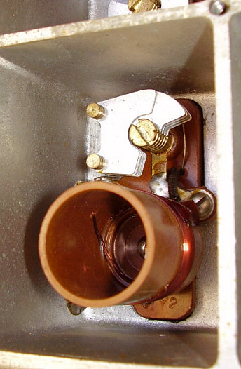
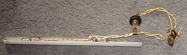
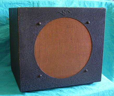
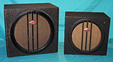
The NC-100 was the first National Co. receiver to utilize an electrodynamic loudspeaker that had its field coil powered by the receiver's power supply. Although there were some SW-5 versions that had push-pull audio output, these receivers had to utilize a "self-powered" electrodynamic loudspeaker. These speakers had an onboard power supply just for the field coil and they were popular in the late-twenties and early-thirties.

NC-101X is introduced with ham band only coverage, black PW-D on most of production, eye tube on early versions (NC-101X introduced during "E" production run, probably Oct-Nov 1936)

1937

Contracts for Airport "Communication Receiver" from Dept. of Commerce, Bureau of Air Commerce Air Navigation Division. DOC-BAC receivers are the RCD and RCE

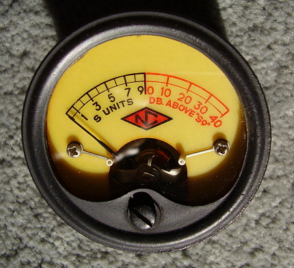
S-meter replaced eye-tube in NC-101X - changeover to S-meter seems to have occurred between runs J to L (runs six, seven or eight, or around mid-1937.) Some earlier NC-101X receivers seem to have been modified to replace the eye tube with an S-meter. Some of these upgrades were obviously rework performed at National and exhibit professional-level installations. Others appear to be "hamster" modifications. For example, NC-101X sn 247-J is a sixth production run receiver but has the later Marion Electric yellow scale S-meter installed instead of an eye-tube or the earlier white face Marion Electric meter. Since some hams sent their receivers to National for repairs or upgrades, it's possible that early production run receivers that have yellow scale S-meters may have been replacements that were installed by National during a repair. It's also possible that late-style replacement S-meters were obtained from National were installed by receiver owners. In general, on original receivers that haven't been reworked, expect to see the white face S-meters from around run J up to around run N. The yellow face S-meter should be installed on receivers from around run P up to around run Y (probably early-1938 up to 1940.) This change also affected the NC-100 and NC-100X and (at the very latest) eliminated the "Art Deco" overlay on those receivers.

Power transformer top cover vent holes eliminated   

Installation of the S-meter switch eliminated the green pilot lamp so all S-meters were illuminated to provide a "power on" indicator. All stock S-meters were manufactured by Marion Electric.

NC-80X and NC-81X AC-DC receivers introduced. Optional power transformer available to convert to AC-only operation. Also a battery-operated version was available.

1938

NC-100A and NC-100XA introduced in June 1938. New direct-read dial, articulated pointer, illuminated S-meter, cabinet height increased to 10.5", weighted tuning knob on early versions. White face S-meter used on earliest production. The transition to the yellow face meter probably coincides with the NC-101X meter change around run-P.

Contracts for "Airway Communication Receivers" begin - the U.S. Civil Aeronautics Authority, the CAA, was formed in 1938. CAA receivers begin with the RCF-2 version. All Airport and Airway receivers use a PW-D with a light gray color Index dial and a black Number Dial with white numerals. This light gray color Index dial is quite different than the bluish-gray Index dial used on the earlier NC-100 PW-D.

NC-101XA introduced. Both versions (direct read dial or PW-D micrometer dial) are available up around mid-1940.

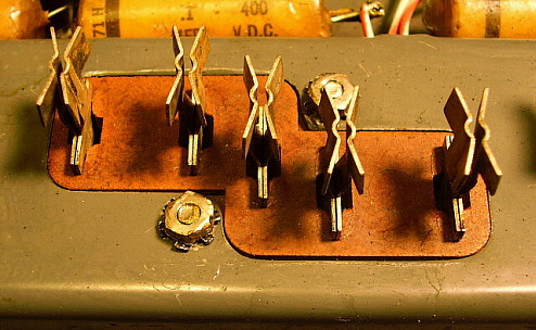
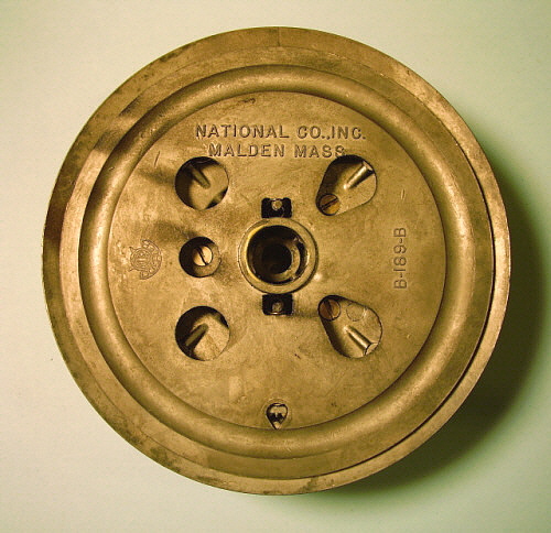
Some models will be found with fiber board, blade screw terminals Antenna and Ground connections. These probably replaced the problem-prone push button terminals found on earlier models. This piece was the transition part that then led to the polystyrene insulated Antenna and Ground terminals with thumb screw fasteners.

1939

Noise Limiter circuit added to NC-100A versions. 6F8G (1stAF/AVC Amp) and 6C8G (Detector/NL) replaced the 6C5 (Detector) and 6J7 (AVC Amp) tubes. The Noise Limiter was also incorporated into the NC-101X receivers along with the tube changes. NL available November 1939. On 
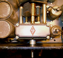
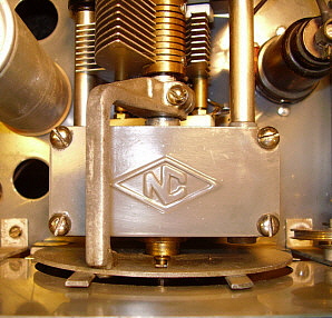
NC-101X with NL, the control is between the RF Gain and the Band Change knob where the National NC diamond logo was engraved. The "NC" diamond logo is relocated on these NL receivers to the upper right corner of the front panel.

By late-1939, NC-101X receivers will use NC-100XA chassis but are built as NC-101X receivers. That is, all holes needed for the "A" direct-read dial are present on the NC-101X chassis although not needed or used. Usually, one side of the chassis will have "101-X" written in orange grease pencil to ID chassis so assemblers know not to install the "A" dial and "A" gear box.

NC-80X and NC-81X not produced after 1939. NC-80X cut-off may be 1938. Neither receiver sold well and examples are rarely encountered today.

1940

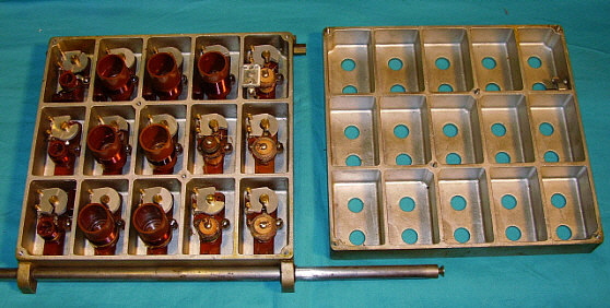
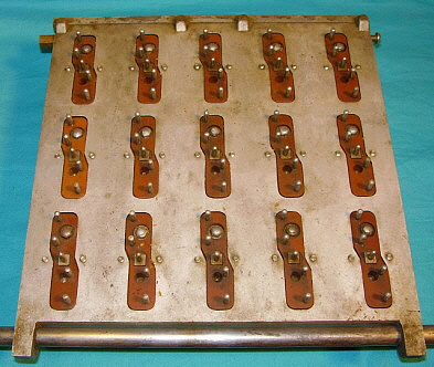
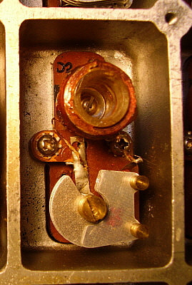
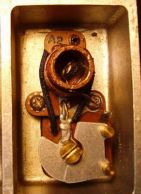
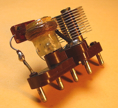
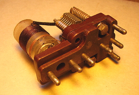
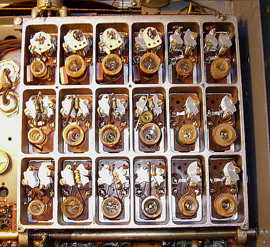
Tuning condenser design changed to replace large bakelite insulator plates with smaller round insulators, thin metal dividers replaced with thicker metal dividers that now support the rotor contact insulators, rotor plate hub changed from brass to steel, support rods dimensions reduced, two screw rear mounting flange. Cost reduction? HRO tuning condenser went through similar changes.

Antenna/Ground thumb-screw terminals with Polystyrene insulator replaces the old "push terminals" with fiber board insulator or the fiber board, screw terminals found on some models.

NC-101X production stops before May 1940. The direct-read dial version - NC-101XA - production may have continued until the NC-200 was incorporated into production (Sept-Oct.)

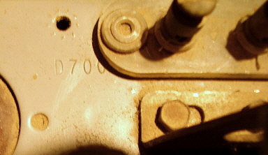
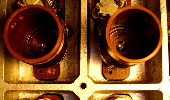
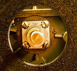
When the two-screw rear mounting flange was used on the tuning condenser, the serial number location had to be moved to the left side of the antenna terminal insulator (nearer to the audio output tubes.)

NC-200 introduced (October) - features both general coverage and band spread coils within the catacomb thus eliminating the need for separate "ham bands only" receivers like the NC-101X or NC-101XA.

NC-200 Crystal Filter changed from variable condenser Selectivity control to six-position switch with five selectivity positions and "off" position. Crystal at 455kc to match new IF frequency.

LO tube changed to a 6J5 triode in NC-200 Series. Many other tube changes in the NC-200, see tube line up in section below "Vacuum Tubes Used in All NC-100 and NC-200 Series Receivers."

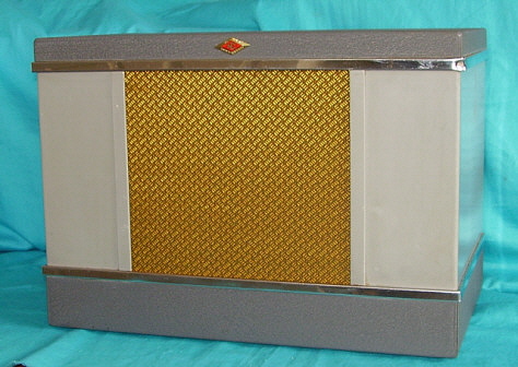
Dec. 1940 QST ad for "Silver Anniversary" NC-200. Special NC diamond insignia on receiver and matching speaker. Also, receiver equipped with brown knobs and brown S-meter case. All round control nomenclature plates, the tuning knob's skirt and the Silver Anniversary NC diamonds are finished in "gold tone." The Silver Anniversary NC-200 celebrated QST's 25th year and wasn't associated with any National anniversary. Silver Anniversary models start as early as C-33 and run until as late as D-639. NC-200 receivers D-700 and D-716 are both standard NC-200 receivers indicating that the Silver Anniversary ended by D-700.

NC-200 early versions will have a flat dial cover that is glass (similar to the NC-100A versions.) Some early NC-200 receivers had plexiglass as the dial cover. Other early NC-200 receiver used the vacuum-molded plastic dial cover but it was mounted using clamps located on the inside of the front panel. Later versions of the NC-200 will have the slightly convex vacuum-molded plastic dial cover that is mounted with two exterior metal strips held to the panel with screws.

1941-45

RAO USN versions - RAO, RAO-1,2,6,7 & 9 built by National, RAO-3,4 & 5 built by Wells Gardner & Company. RAO-2 through 9 have double preselection. All versions have .54mc to 30mc coverage. Early versions have 500 Z ohm audio outputs, RAO 7 & 9 have 600 Z ohm audio output. RAO-2 thru 6 are 17.5" wide, RAO-7 & 9 are 19" wide. RAO-6, 7 & 9 don't have S-meters installed but have an output for panadaptor use instead. First 200 RAO-6 receivers were equipped with S-meters but the remaining production had the panadaptor set-up. RAO-7 & 9 have 
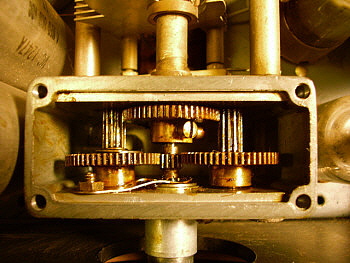
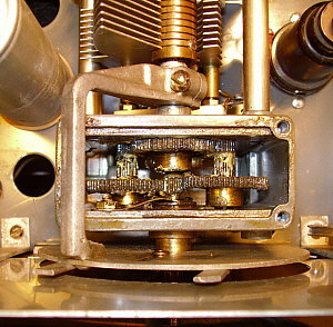
unique molded skirt bar knobs. Gears used in the later gearboxes are changed from brass gears to cast pot metal gears for wartime material conservation. Late gearboxes have an added idler gear with mechanical stops to limit the total main tuning shaft revolutions to slightly over ten turns. The double pre-selection design upgrade with the add-on chassis, coil box and sheet metal cabinet pieces certainly pre-dates WWII and may have been available to USN as early as mid-1941. As an example, the R-116 USCG receiver from a May 15, 1941 contract has dual preselection incorporated identically to the RAO-2 receiver although the receiver itself has significant differences in front panel layout, mechanical design, frequency coverage and tubes used. Also, utilizes a separate power source (AC power supply, batteries or other shipboard power source.)

RBH USN version of NC-100XA with special frequency coverage of 300kc to 1200kc and 1700kc to 17.0mc, IF changed to 1500kc, single ended audio, 500 Z ohm output. Later versions, starting with RBH-1, added an extra RF amplifier similar to the RAO and for similar reasons. It's likely that the RBH series follows the same evolution that the RAO did.

NC-100ASD Signal Corps version, ca: 1943 - replaced AM BC coverage with 200kc to 400kc, single 6V6 audio output with 500 Z ohm output transformer. Serial number is stamped into the chassis between the 6C8 and 6F8 tubes. Serial number is three numerical digits. Highest reported numerical SN is 948. Two serial numbers have been reported that incorporate the letter "A" as a prefix, e.g., A059. It's probable that the "A" indicates "1000" and A059 would be 1059 for a numerical conversion. A578 has also been reported which implies production quantity was over 1500 receivers. As to why the letter prefix? It may have designated a second production run for the same contract and was National's way to keep track of the receiver manufacture (just conjecture.) The ASD may have been a replacement for NC-100ASC (aka AN/GRR-3) that might have been a "militarized" NC-100XA.

NC-200FG, R-115 (USCG), NC-240C and NC-240CS produced during WWII. These receivers do not have band spread function. The CS version had 200kc to 400kc band to replace the AM BC band. The R-115 has no crystal filter, no tone control, no S-meter and no logging scale. Covers 200kc to 400kc and 500kc to 18mc.

NC-100A, NC-100XA and NC-200 offered in the National section of the 1945 Radio Amateur's Handbook. None of these receivers, or any other items listed, were actually available during the war and each page of the catalog states "Priorities are required for all products in this catalog until otherwise released by the War Production Board." The intention of the catalog was to show what National was probably going to have available after the war ended.

In 1945, Schuttig & Co. modified RCL and RCK Airway receivers into RCP Airway receivers. The RCK-N built during WWII used a 1560kc IF and tuned 200kc to 800kc and 2.5mc to 23.5mc in five tuning ranges. 6C5 tubes, the detector and the squelch tubes, are replaced with 6J7 tubes in the RCQ versions.

1946-49

NC-240CS sold to the civilian market in post-war 1945 as a 1946 model. In 1946, National designated the CS version as a "commercial receiver"

NC-240D returned the band spread function and was sold from early-1946 up to 1949. Note in SN Log that F-104 is a CS model w/o BS and that F-478 is a D model with BS. Both receivers are from the same production run "F" which indicates that this change was rapidly incorporated. Early NC-240D dials are similar to NC-200 dial with all four Band Spread scales near the center of the circular arc of the scales. Later NC-240D dials will have the Band Spread scales alternating with and located above the General Coverage scales on bands D, C, B and A.  

In 1948, National Electrical Machine Shops (NEMS) modified RCL and RCK Airway receivers (or parts from these types of receivers) into RCQ Airway receivers

In 1948, some NC-240CS receivers were produced as RCR Airway Receivers. The RCR is the last National Airway receiver produced based on a Moving Coil receiver design.


Coil Catacomb Details

The "Moving Coil" Catacomb - Just as the plug-in coil sets and the PW gear drive and tuning condenser are the "heart" of the HRO design, the "Moving Coil" Catacomb along with its N-PW gear drive and tuning condenser are the "heart" of the NC-100 Series. The Coil Catacomb is a two-piece cast aluminum box containing fifteen tuned coils and their respective trimmer variable capacitors. Each coil is inside a singular chamber that completely shields all of the coils from one another and from the rest of the receiver circuitry. Each coil assembly is mounted with two screws accessible by removing the catacomb cover. The coil insulator blocks each have five short, stubby pins that make the contact to the tuning condenser section to complete the tuned circuit. Each coil assembly is identified with a letter-number combination to assure proper installation. The insulator material is National's brown bakelite mixture called R-39, noted for its superior quality over standard bakelite. Robust in construction, the Coil Catacomb assured that the tuned circuit alignments stayed in adjustment and that receiver stability was solid and consistent of long periods of time. The engagement contacts are located in R-39 insulator blocks that are mounted under the tuning condenser. This allows the connections from these contacts to be very short and accomplished with TC wire. The contacts are dual entry in design allowing the Coil Catacomb pins to enter from either side. This allows the bands to be changed from any direction.

 The two-piece engagement contacts are insulated from each other and when the connections are soldered on the top side (under the tuning condenser) both sides of the upper part of the contact are soldered together. The exception is the foremost LO contact. Since the LO only requires four connections, the unused contact is wired to act as a screen voltage switch for the RF and IF amplifiers to eliminate noise during band changes on the early models of the receiver. Later models used this contact for the RF amplifier cathode return to "mute" the receiver during band changing. The almost "sealed" nature of the catacomb construction generally protects the coils and trimmer capacitors from damage. Nowadays, most catacomb coils are still in good condition even if the rest of the receiver has not faired so well.

NC-100 Coil Assembly Identification - Each coil assembly is marked with a letter and a number that identifies its frequency of operation and its function in the circuit. Coil assembly identification will either be engraved or ink-stamped, depending on when it was manufactured (see photo right.) Coil sets A through E are generally found in any early single-preselection catacomb receivers that tune .54mc to 30mc. Coil sets A through D and coil set H are found in National Airport receivers. Some NC-100ASD receivers will have G coils in place of H coils. NC-200 Series coil assemblies are similarly identified.

A = 14mc to 30mc    A1 =  RF AMP,   A2 = MIXER,   A3 = LOCAL OSCILLATOR

B = 6.5mc to 14.5mc  B1 = RF AMP,   B2 = MIXER,    B3 = LOCAL OSCILLATOR

C = 3.2mc to 6.5mc   C1 = RF AMP,    C2 = MIXER,    C3 = LOCAL OSCILLATOR

D = 1.3mc to 3.2mc   D1 = RF AMP,    D2 = MIXER,    D3 = LOCAL OSCILLATOR

E = .53mc to 1.3mc    E1 = RF AMP,    E2 = MIXER,    E3 = LOCAL OSCILLATOR

F = .49mc to 1.04mc  F1 = RF AMP,    F2 = MIXER,     F3= LO  - NC-200 Series only

G = 200kc to 400kc   G1 = RF AMP,    G2 = MIXER,    G3 = LO  - Some NC-100ASD

H = 200kc to 400kc   H1 = RF AMP,    H2 = MIXER ,   H3 = LO  - Airport Rcvrs, NC-100ASD

NC-101X Coil Assembly Identification - Since the NC-101X tunes ham bands only and band spreads each range, slightly different coils and trimmers were required to work with the "band spread" main tuning condenser. The identifications on the NC-101X coil assemblies use only numerals and are tied to the ham bands that are covered. Therefore, 16 denotes 160 meters while 8 denotes 80 meters and 4 denotes 40 meters, 2 denotes 20 meters and 1 denotes 10 meters. As with the NC-100 coils, suffix numbers 1, 2 and 3 denote RF (1,) Mixer (2) and LO (3). Thus, 16 1 is the 160 meter RF coil or 4 3 would be the 40 meter LO coil. As with the NC-100 coils, the identifications are stamped into the insulator-base. (see photo right.)

16 = 160 meters     16 1 = 160 RF AMP,   16 2 = 160 MIXER,    16 3 = 160 LO

8   =   80 meters       8 1 = 80 RF AMP,       8 2 = 80 MIXER,        8 3 = 80 LO

4   =   40 meters       4 1 = 40 RF AMP,       4 2 = 40 MIXER,        4 3 = 40 LO

2   =   20 meters       2 1 = 20 RF AMP,       2 2 = 20 MIXER,        2 3 = 20 LO

1   =   10 meters       1 1 = 10 RF AMP,       1 2 = 10 MIXER,        1 3 = 10 LO

NC-80X Coil Assembly Identification - The NC-80X (and the NC-81X) uses a smaller catacomb since the receiver doesn't have an RF amplifier section. The catacomb is driven into position using a chain drive mechanism rather than the rack and pinion used for the NC-100 series catacombs. Only two coil sets per band are used, those being a Mixer coil assembly and a LO coil assembly. Since the IF used in both receivers is 1560kc, both Mixer and LO coils are somewhat different than the NC-100 coils. Each NX-80X coil assembly is identified using the letters W, X, Y and Z for frequency ranges and the numerals 1 or 2 for function. The assignment of the highest letter to the highest frequency coil set departs from National's usual assignment of the letter A to the highest frequency coil sets. But then, the entire NC-80X coil catacomb is entirely different from the NC-100 catacomb.

As an example, coil assembly X2 would be for tuning range 1.7mc to 4.6mc and for the LO function. The identification is stamped in the base of the coil assembly.
 

W = .55mc to 1.5mc          W1 = MIXER       W2 = LO

X  =  1.7mc to 4.6mc          X1 = MIXER        X2 = LO

Y  =  4.3mc to 12.0mc        Y1 = MIXER        Y2 = LO

Z  =  11.4mc to 30.2mc      Z1 = MIXER         Z2 = LO


Shown in the photo to the right is the NC-80X coil assembly Y2 which is for the 4.5mc to 12.0mc band and is the Local Oscillator coil function. Note the wire loop inside the coil form that is used for the low-end of the dial tracking adjustment. The air variable trimmer is for the high-end of the dial tracking adjustment. Unlike the cast aluminum cover for the catacomb used in the NC-100 series, the catacomb cover for the NC-80X is aluminum sheet metal.
 

More Coil Assembly Identification Confusion - Coils sets employed in the later RAO and RBH receivers with double preselection will have four coil sets per band. They are numbered 1 though 4 to identify the function and with letters to identify frequency coverage. The RAO bands are A through E and cover 30mc down to .54mc. The RAO coils for the 1st RF Amp covering 14mc to 30mc would be A1 and the LO for the same band would be A4.
The RBH also has its bands identified as A through E but bands E and D cover different frequencies than E and D on the RAO. The RBH coil assemblies are also identified as A through E even though they are different from the RAO coil assemblies - they are identified just like the RAO receiver's coil assemblies. RAO IF is 455kc and the RBH IF is 1500kc which means the LO and Mixer coil assemblies are different. In fact, band D and E LO assemblies both have padder capacitors on the RBH coil assemblies. The RCK-N Airport Receiver has two LF bands, 200kc to 400kc and 400kc to 800kc. These coils are identified as "H" and "G" respectively, while the remaining 2.5mc to 23.5mc coils are "C," "B" and "A" although they cover slightly different frequencies than the RBH coils or the RAO coils. As far as any markings other than the letter-number ID, there aren't any.

Shown in the photo to the right are the RF amplifier stage coils for the RCK-N receiver. Note that the 200kc to 400kc coil is identified as H1. The 400kc to 800kc coil is identified as G1. The 2.5mc to 5.5mc coil is identified as C1.

Just to keep the confusion going, National decided to change the whole band ID concept of letter A designating highest frequency band with the WWII RBL Regenerative LW Receiver. Although not a catacomb receiver, it was generally paired with and looks very similar to the RAO receiver. With the RBL, band A is the lowest frequency band (15kc up to 30kc) and band E is the highest frequency coverage (about 270kc up to 600kc.)

On the NC-200 and NC-240 receivers, with their very different coil assemblies that included four sets that had a bandspread function, still the letter-number ID remains the same. That is, the highest frequency coverage band is ID'd as Band A and the associated coil assemblies are also ID'd as A1, A2 and A3. NC-200 and NC-240 coil assemblies have seven stubby pins to provide for the bandspread function on 80M, 40M, 20M and 10M. Since the NC-200 and NC-240D receivers have six general coverage bands, the coil assembly letters are A, B, C, D, E and F. The four bandspread bands are derived from coil assemblies A, B, C and D. The A, B, C and D local oscillator coil assemblies have three trimmers and an inductance loop for adjusting the tracking on both the general coverage band and the ham band bandspread.

National apparently only wanted the coil assemblies within the individual catacomb to be identified for proper placement for the particular model receiver. It was probably thought "why have several different ID combos when nobody is going to be replacing the coil assemblies anyway." If a specific coil assembly was damaged beyond repair a new one could always be ordered from National specific to the model receiver it was for. Nowadays, while it's possible to find receivers that have had some tampering to the coils within the catacomb, it is rare. Most catacombs are in good condition because of the almost "sealed" nature of the housing which results in very few problems with the coil assemblies.

NC-100 Coil Assembly

NC-200 Coil Assembly


Inductance Loop

The individual coil assemblies are mounted into the catacomb with two screws - see photo right. These are 6-32 thread and screw into the catacomb base for mounting (WWII receivers used philip's head screws.) The photo above-left shows how the NC-100 series coil assembly looks - note the five pins. The photo above-center shows the NC-200 style coil with its seven pins. When removing an individual coil assembly or a particular section (coil assemblies 1, 2 & 3 of any letter designator) make sure the catacomb is disengaged from the pin contacts by setting the band switch in between bands. Then loosen the two screws until they are no longer threaded into the catacomb base and then lift out the coil assembly. Reinstall in the reverse and then check engagement by operating the band switch. Early versions (pre-WWII) and post-war versions will use round-head blade screws instead of philip's.

The photo above-right shows the alignment inductance loop that are in most of the NC-100 series coils A, B, C and D for adjustment of the low end of the dial tracking. This not only is used on the LO but also on the Mixer and RF Amp coils. Moving the coil loop slightly will change the inductance allowing the low end to be set exactly. During alignment, by using a plastic rod to manipulate the loop, you can have the receiver operating and set the loop position exactly for proper low end tracking (this wasn't possible on National's HRO receivers.) High end of the dial tracking is adjusted with the air variable trimmer. The lower frequency coils E or G will have a padder compression trimmer to adjust the low end dial tracking on the Local Oscillator coil assembly.

The photo to the right shows the NC-200 catacomb with its six band coverage. Note that there are many more air variable capacitors for adjustment. The two lowest frequency bands have padder capacitors on the LO and the four highest frequency bands have ceramic trimmers for the ham bandspread adjustments. To avoid confusion during alignment, National assigned the same designator for trimmers that performed the same function on each band. For example, the four bandspread RF amplifier trimmers are all designated as C-54 and the four mixer bandspread trimmers are designated C-55. Sounds confusing but it actually works fine, as long as you have the alignment instructions and drawings to guide you. LO coils are at the top, Mixer coils in the middle and RF coils at the bottom. Note LO coils on the four HF bands have three variable caps each. One for General Coverage, one for Bandspread trim and one for Bandspread padder. GC low end uses coil loops.


photo above: NC-200 coil catacomb. Note there are six sets of coils.


PW-D Details

PW-D Micrometer Dial - The NC-100 used the same PW-D micrometer dial as the HRO receiver but with different paint colors. Initially, the NC-100 used a PW-D that had the Index Dial painted a bluish-gray and the Number Dial was painted red with white numerals. This rather dramatic color combination went well with the "deco" styling of the metal overlay panel of the NC-100. It appears that the NC-100X versions changed the Number Dial to black with white numbers. This may have been because National believed the NC-100X was more for CW and hams while the red Number Dial of the NC-100 would appear more to the SWL. When the NC-101X version was released, National wanted the receiver to appear like the HRO, so the standard HRO Senior PW-D was fitted to that receiver. Some of the advertising photographs of the NC-101X show it with the light gray PW-D installed but it looks like most of the actual production used the black PW-D, like the HRO Senior. Though "black" describes the color of the PW-D index dial in normal room lighting, when in sunlight or any bright light, the index dials will vary in color from a gunmetal gray-black to and olive-bronze black. The colors are usually only noticeable in very bright light (like a "flash" photograph.) The gray PW-D with black Number dial was standard for all Airway Receivers.
PW-D Mechanics - Internally, all PW-D dials are the same and work by rotating the Number Dial on an elliptic hub. The Number Dial is gear-driven by the Index Dial that is also set-screw coupled to the main tuning shaft of the N-PW gearbox drive. There are two moving parts (Index Dial and Number Dial) and seven stationary parts that make up the micrometer dial. The Index Dial has five windows with ten index marks between each window. The Number Dial displays sequential numbers that increment by 10 as each window comes into view at the top of the dial. The Number Dial has 0 to 500 numbers incremented by 10 and each revolution of the Index Dial increments the numbers by 50 (five windows viewed with each revolution.) With ten revolutions total the numbers displayed are 0 to 500 incremented by 10. Since the Index Dial is 4.625" in diameter, its circumference is 14.53" and with ten revolutions the total span is 145.3" or just over 12 feet (12.1'.) On the NC-101X receivers, the ham bands each span 50 to 450 on the PW-D. This is 80% of the full 500 divisions thus the ham bands equate to a linear dial that is 9.68 feet long.

As to the two moving parts (Index Dial and Number Dial) and seven stationary parts - besides the Index Dial and the Number Dial there are two springs that hold the two dials together, three flat-head screws to mount the HRK-style knob to the Index Dial and a single set screw on early versions. During WWII the set screws were increased to two. Elegant in its simplicity, about the only thing that ever goes wrong with a PW-D is caused by technicians who carelessly disassemble the dial and then reassemble it incorrectly.


photo above:
The early NC-100 PW-D. These PW-Ds seem to only have been installed on the NC-100 and then perhaps only on the first production run of those receivers.

PW-D Micrometer Dial Servicing - NC-100(X), NC-101X, Airport Receivers

The PW-D Micrometer dial only has two moving parts and seven stationary parts. Elegant in its simplicity of design, it is very easy to work on if you know the "tricks." About the only thing that goes wrong with the dial is that it becomes noisy in operation and might have a rough feel when tuning. Synchronization might be a problem too - if the dial was reassembled incorrectly. The inner dial has gear teeth cast into its inner perimeter and also has the bearing that fits on the elliptic hub of the tuning shaft bearing housing. The outer dial has mating gear teeth that are cast into a rim projection and a hub that is set screw attached to the tuning shaft. By having the inner dial ride on the elliptic hub cast into the tuning shaft bearing housing, the gears of the two dials engage and as the outer dial is turned, by way of the mating gears, it turns the inner dial and since the outer dial is coupled to the tuning shaft, it also moves the tuning condenser. The elliptic hub is actually round but since the tuning condenser shaft exits the hub "off-center," the hub bearing surface appears as an ellipse to the tuning condenser shaft. This eccentric placement forces engagement of the inner and outer dial gears, thus driving the inner dial with the rotation of the outer dial.  >>> >>>  To disassemble the Micrometer dial, first tune the receiver to "250" then loosen the dial set screw. The dial should come off of the elliptic bearing hub and tuning condenser shaft with very little effort. With the PW-D dismounted, look at the back of the dial and, if the PW-D was synchronized prior to removal, you will notice that the three screws that hold the knob to the dial appear through cast holes in the inner dial. Also note that the two springs that hold the inner dial to the outer dial are pointing straight up. Remove the knob. Then remove the two springs - their ends fit into slots at the end of the shaft hub of the outer dial (where the set screw is.) Now the dials can be separated. Examine the cast gear teeth for condition. Usually they are in good shape and all that is present is old dried grease. Use a tooth brush and light oil to remove all of the old grease and then apply a light coating of Lubriplate (or any modern light weight grease) to the inner dial gear only. Position the inner dial to the "250" position with the cast holes lined up for the knob screws. Then install the two retaining springs. >>>

>>>   Before putting the PW-D back on the receiver, lightly grease the elliptic bearing hub (since the inner dial rides on this it should be clean, smooth and lightly greased.) The PW-D should already be set to "250" and the receiver condenser should not have been moved. Place the PW-D back on the receiver by carefully noting how the elliptic hub requires the inner dial to be slightly down from center. If you have assembled the PW-D correctly, it will just slip right on to the hub. Tighten the set screw and test the operation - it should be ultra-smooth and very quite in operation. If your PW-D dial doesn't just slip onto the elliptic hub then it isn't assembled correctly. It can go together two ways, one correct and one 180º out. If your PW-D doesn't just "slip onto" the bearing hub, read the section below "Correct Assembly of the PW-D Micrometer Dial - Details."

Around the beginning of WWII, a guide pin was added to the inner dial, located just above the inspection/grease hole. This pin limits the vertical movement of the inner dial and was probably installed to keep the gear alignment fairly tight and allow easier installation of the PW-D onto the elliptic hub. Later production dials will have this guide pin molded in the casting of the inner dial.


photo left: Two moving parts and seven stationary parts are all that are used in the PW-D. A second set screw was used during and after WWII - total of eight stationary parts then.

Correct Assembly of the PW-D Micrometer Dial - Details - When the PW-D is assembled correctly, it will just slip onto the elliptic hub. If you are trying to force the PW-D onto the hub, then the PW-D is assembled incorrectly. There are two ways that the outer index dial can interface with the inner number dial. One is correct and one isn't. Look carefully at the photograph to the right noting the location of the smaller round hole, the two oval holes, the "NATIONAL CO., INC." embossing and the location of the screws that are for mounting the knob. If you orient the reverse side of your assembled PW-D in this position and then look at the outer dial, you should see "250" centered in the window that is directly behind the "NATIONAL CO., INC." embossing.

To check your assembly,...position PW-D as shown in photograph to the right. You should see the following:

1. "NATIONAL CO., INC" embossing should be at 12 o'clock

2. Small round hole should be at 9 o'clock

3. Two oval holes should be at 2 o'clock and 4 o'clock

4. Note that all three knob screws are directly centered in the small round hole and the two oval holes

5. Turn dial over from right to left and you'll see "250" centered in the window at 12 o'clock (the window should be directly behind the embossing "NATIONAL CO., INC" on the back of the inner dial.)

6. Push the inner dial so that the "250" appears closer to the bottom of the window. You might hear a slight "click" as the inner dial gear teeth mesh with the outer dial gear teeth. You may only "feel" the inner dial mesh with the outer dial.

If your assembled PW-D meets this criteria, then it will slip right onto the elliptic hub. Sometimes even though everything is assembled correctly, the PW-D still won't fit onto the elliptic hub. With the PW-D removed, push the number dial into the gears of the index dial while very slightly moving the position of the number dial. You'll probably hear a "click" as the gears mesh correctly. Check that the "250" is still centered in the index dial window. Now the PW-D should slip onto the elliptic hub easily. Sometimes, instead of hearing  the "click", you'll just "feel" the correct meshing of the gears. You must have the gears meshed before the PW-D will fit onto the hub easily.


photo above
: Correctly assembled PW-D micrometer dial looking at the back side.

Dismounting a Stubborn PW-D (it's not the same as an HRO) - Sometimes removing the PW-D Micrometer dial proves to be a very difficult operation. Almost always, the difficulty is caused by excessive marring of the tuning shaft by the knob set screw(s.) If everything seems it indicate that the PW-D is not coming off of the shaft no matter what, this is the procedure necessary to remove the dial. First, you'll need a couple of right-angle screw drivers. I usually have to make them because everything commercial is too big to fit between the back of the front panel and the tuning shaft elliptic bearing hub screws. Make at least two that have different angles for the blade engagement. You'll also have to add a slight "S" bend to the shaft of the angled screw drivers. This applies only to the NC-100, NC-100X, and NC-101X because these receivers are in cabinets that have a non-removable lip that impedes easy access to the hub screws. If the receiver is a rack mount, e.g., Airport receiver, then there is ample access and a straight shaft angled screw driver can be used.

Now, using the right-angle screw drivers, loosen and remove the four screws that mount the elliptic bearing hub. You'll have to use a small dental mirror to see the screws for proper blade engagement. It's difficult but it can be done. The bearing hub is just slightly spring loaded with a small dual leaf spring so when the last screw is removed the hub will just slightly come forward. Now, remove the entire PW-D and the bearing hub and the main dial drive shaft out through the round hole in the receiver's front panel. Now, remove the knob from the PW-D assembly. This provides access to the front of the tuning shaft. Then, using a soft metal drift, gently tap out the shaft from the PW-D dial assembly.   >>>

>>>   You will have to reassemble the gear box and set the anti-backlash per the instructions in the "Servicing the NC-100 Series Gear Box" section above. Also, be sure to dress down the marring on the tuning shaft so the next time the PW-D has to be removed, it will be an easy job. 

With the NC-100A Series, the main tuning shaft diameter was greatly reduced - from 5/16" diameter to 3/16" diameter. The smaller tuning shaft diameter doesn't seem to have the marring problems that the large, early style, PW-D shafts experience. Perhaps the material is harder since the diameter was reduced. Also, you'll find that the NC-100A Series receivers don't need an elliptic hub bearing. Generally, tuning knob removal on the later receivers is easy and problem-free.

NOTE: When remounting the bearing hub note that "TOP" is embossed on one of the flanges. This flange obviously must be mounted up. This is important because it positions the elliptic bearing correctly for the PW-D dial.


Servicing the NC-100 Series Gear Boxes

The gear box used in the NC-100 Series of receivers was designated as the PW-N. This gear box is substantially different from the box used in the HRO receiver although both require an elliptic hub to allow use of the National PW-D Micrometer dial. The gear box is accessed by removal of the cast metal cap with the "NC" diamond embossed on it. Four fillister head screws secure the cap to the gear box. >>>


photo above
: Early style gear box cap

>>>  The NC-100 gear box uses a main tuning shaft to which is mounted  a small drive gear which simultaneously engages two larger gears that are mounted in bearings that are located in the back and front of the gear box housing. The left side gear is able to rotate on its shaft and is spring loaded so it acts as the anti-backlash gear. At the rear of each of the two larger gears are longer small gears that simultaneously engage a single large condenser drive gear. The thrust pin bearing of the main tuning shaft enters into a socket bearing that is in the end of the condenser tuning shaft (provides rear support and some thrust action.) A small dual leaf spring also presses against the flange on the main tuning shaft to reduce end play. With much smaller gears being employed and with the reduction used in the gearing, the NC-100 gear box has a very "light" feel and is much easier to turn than the HRO box.


photo above: Inside the early NC-100 gear box

In the early gear boxes that operate with the PW-D micrometer dial an elliptic hub is integral to the main tuning shaft bearing. Since the elliptic must be properly mounted, "TOP" is embossed on one of the mounting flanges so that correct installation is easy. Shown in the photo to the right is the elliptic hub used in the NC-100 versions as viewed through the port in the front panel with the PW-D removed.


photo above:
The Elliptic Bearing Hub as viewed thru the front panel port on a rack mount RCF Airport receiver.

Cleaning and Lubrication -  The early gear box has a cast metal top cap that is mounted with four fillister-head screws. When this top cap is removed, the gears are accessible. Most of the NC-100 gear boxes don't have an excessive amount of dried-up grease inside but they will need thorough cleaning and re-lubrication for smooth operation. I usually use WD-40 applied with an acid brush to dissolve and loosen the dried grease. The old grease and residual WD-40 is then removed with a "dry" acid brush and a cotton cloth rag. You probably won't be able to remove 100% of the old grease but it really isn't necessary. Apply a high quality modern light grease to all of the gear teeth. Check the operation which should be very smooth and easy to rotate the tuning condenser via the front main tuning shaft.

Setting the Anti-Backlash - If you have to remove the elliptic hub you will unload the anti-backlash spring located on the left side drive gear. The anti-backlash setting will determine how "lightly" the gear box "feels" when tuning. A good setting is about four or five teeth. You'll feel the anti-backlash spring load at about two teeth but you do need a bit more load for proper operation. Too much load will cause gear wear and a "heavy" feel to tuning. Too little load will cause backlash and a very light feel to tuning. You'll have to hold the right side gear in place and then, using your other fingers, hold the anti-backlash gear in place while you insert the main tuning shaft and elliptic hub assembly. Besides engaging both large gears, the end of the main tuning shaft has a small thrust end pin that fits into the thrust socket bearing located in the end of the condenser drive shaft, so be sure that the assembly is fully seated. You'll feel a slight pressure being exerted by the dual leaf spring while you hold the bearing hub in place. Be sure that the "TOP" flange is up and then install the four mounting screws.

NC-100A Versions - Gear Box Details - With the change to a direct readout tuning dial, the gear box used on the NC-100A versions required a few modifications. First would be the elimination of the elliptic bearing hub. Since a PW-D was not used there was no need for the elliptic part of the hub. The new tuning dial featured a tracking "band in use" articulated pointer that used a rather large mechanism to support the pointer. Note in the photos right and left that a large cast metal arm is mounted to the tuning condenser shaft. This arm is cast to have a bend that goes over the gear box and then is attached to the disk of the articulated pointer mechanism. This disk also "rides" on a bearing that is part of the main tuning shaft bearing hub (which isn't elliptical anymore.) To remove the cap, which is now a flat metal piece with the "NC" diamond embossed on top, the pointer mechanism arm must be moved to one side of the other of the gear box top (tune the dial to minimum or maximum frequency on any band.) When the cap is removed, it will be noted that the NC-100A version gear box is almost the same as the earlier gear boxes. The two reduction gears that are driven by the main tuning shaft have been moved slightly so that the right side gear is mounted somewhat higher than the left gear. Otherwise the gear box is identical to the early versions. Servicing is the same as for the early box.

NC-200 and NC-240D Versions - Early NC-200 receivers have a set of gears that allow for an anti-backlash adjustment. The ratio thru the gear box is 1:1. By production run D the gears and anti-backlash adjustment were eliminated. Although there appears to be a gear box in these receivers, seeing the photo to the left reveals that the tuning shaft merely passes through the box and drives the tuning condenser. The gear box housing is merely acting as a bearing for the tuning shaft. The tuning on either early or late NC-200 receivers works on the large diameter fiber disk that is rim driven.

RAO and Other Military Versions - The RAO-2 and later versions will not have the articulated pointer mechanism since this feature was eliminated to simplify the construction and maintenance of the receiver. The cast metal arm that carried the articulated pointer mechanism was removed. To further strengthen the dial itself a bracket is mounted between the top of the gear box and the back of the main dial. You will notice that the RAO dial will have two screws near the top of the dial that are for mounting the bracket. To access the gear box on an RAO will require removal of the tuning dial bezel. This will require removing the associated knobs and control mounting nuts (if used.) With the tuning dial bezel removed, you'll have access to the two screws that mount the top part of the bracket. The mating nuts are located on the backside of the dial. Once this part of the bracket is dismounted, then the two screws that mount the lower part of the bracket to the gear box cap can be removed. The gear box cap is held in place with two hex head screws that are on the sides of the gear box. Loosen the hex head screws to remove the cap. To see how this bracket is attached, reference the photo of the RAO-3 chassis above in the section "WWII Versions." Once the gear box cap is off the remainder of the RAO gear box servicing is just like the NC-100A gear box. The early RBH gear box is similar to the NC-100A while later versions are like the RAO gear box. The NC-100ASD gear box is similar to the NC-100A box. Later WWII gearboxes will have cast pot metal gears rather than brass gears.
Setting the Anti-Backlash on the RAO Receivers - The NC-100A/RAO direct reading dial complicates the anti-backlash adjustment but, unless the receiver has been disassembled or carelessly worked on, the anti-backlash should not require adjustment. Check the tuning and if any minute movement of the tuning knob doesn't also move the tuning condenser, then the anti-backlash needs adjustment. Unfortunately, the RAO versions of the receiver will require substantial disassembly of the tuning dial assembly. The receiver dial escutcheon has to be removed. The entire dial, logging dial and main dial pointer have to be removed. With the gear box cover removed and with unobstructed access to the front of the gear box, the front bearing hub mounting screws have to be removed. Then the hub can be slightly pulled forward. This disengages the drive gear from the idler gears and allows adjustment of the spring-loaded gear on the left side. By holding the right side gear, the left gear is rotated clockwise about a quarter of a turn and held in place. Then the hub and front tuning shaft are slid back into the gear box. The tuning shaft gear keeps the anti-backlash gear in place and the spring-loading eliminates any backlash in tuning. You have to test the tuning to make sure there isn't any binding. If the gear mesh seems too tight, then readjust the anti-backlash for slightly less than a quarter of a turn. Also, you have to watch the idler gear below the tuning shaft gear. This idler gear has an embossed projection that interacts with another projection on the tuning shaft gear. The difference in the ratio of the two gears results in these two projections acting as "stops" once every ten turns. The easiest way to set the stop position is to insert the tuning shaft into the gears with the tuning condenser fully meshed. Have the idler gear stop on the left side of the tuning gear stop. Insert the tuning shaft while holding the drive gears with the proper backlash. Once the gears mesh, then test the gear stop set by tuning the gear box from the low end to the high end of the range. At the high end the stops should again hit. When set correctly, the tuning stops will be slightly below the beginning of the dial scales on the low end and rotate to quite a bit beyond the dial scale at the high end. When everything is set correctly, the tuning shouldn't bind and no backlash should be felt when the tuning and the stops should happen as described. Be sure to check that the tuning condenser gear set screws are tight otherwise you will still have some backlash. Reassemble the receiver. Fortunately, it's fairly rare to have to do more than just lubricate this style of gear box.  
 

Vacuum Tubes Used in All NC-100 and NC-200 Series Receivers

Unlike the HRO receiver that continued to use glass tubes with six and seven pin bases up into WWII, the NC-100 was introduced utilizing octal base tubes with the majority of those tubes being metal tubes. The eye-tube, the audio output tubes and the rectifier tube are the only glass tubes used and the rectifier and the eye-tube are the only non-octal based tubes.

It's interesting that James Millen published a QST letter in 1937 that seemed to condemn the 6.3vac glass tubes used in the HRO in favor of using the even older 2.5vac tubes and yet here was the NC-100 sporting the latest types of tubes available. Many speculate that over-stocking of older parts was the reason for the position that National had on the HRO, although maybe National didn't want to change the design of an obviously superior performer like the HRO. Eventually, in 1945, the HRO was produced with octal tubes and the performance wasn't diminished at all (HRO-5.)

NC-100,100X,101X:  RF = 6K7, Mixer = 6J7, LO = 6K7, IF1 = 6K7, IF2 = 6K7, Det = 6C5, AVC Amp = 6J7, BFO = 6J7, P-P AF Output = 6F6(2), Eye Tube = 6E5, Rect = 80

NC-100, 100X (w/NL):  RF= 6K7, Mixer = 6J7, LO = 6K7, IF = 6K7(2), Det/NL = 6C8, BFO = 6J7, 1st AF/ AVC = 6F8, AF Output = 6F6(2), Rect = 80

NC-100A,100XA:  RF= 6K7, Mixer = 6J7, LO = 6K7, IF = 6K7(2), Det = 6C5, AVC = 6J7, BFO = 6J7, P-P AF Output = 6F6(2) Rect = 80

NC-100XA(w/NL) 101X(w/NL,)101XA(w/NL):  RF= 6K7, Mixer = 6J7, LO = 6K7, IF = 6K7(2), Det/NL = 6C8, BFO = 6J7, 1st AF/ AVC = 6F8, AF Output = 6F6(2), Rect = 80

NC-80, NC-81X:   Mixer = 6L7, LO = 6J7, IF = 6K7(3), Det = 6C5, AVC = 6B8, BFO = 6J7, AF Output = 25L6, Rect = 25Z5 (not in "B" models - battery versions)

NC-200:  RF = 6SK7, Mixer = 6K8, LO = 6J5, IF1 = 6K7, IF2 = 6SK7, Det/NL = 6C8, AVC = 6SJ7, BFO = 6SJ7, 1stAF/Phase Inv = 6F8, P-P AF Output = 6V6(2), Rect = 5Y3

NC-240D:   RF = 6SK7, Mixer = 6K8, LO = 6J5, IF1 = 6K7, IF2 = 6SK7, Det/NL = 6SL7, AVC = 6SJ7 or 6V6, BFO = 6SJ7, 1stAF/Phase Inv = 6SN7, P-P AF Output = 6V6(2), Rect = 5Y3

NC-100ASD:  RF = 6K7, Mixer = 6J7, LO = 6J7, IF = 6K7(2), Det/NL = 6C8, 1st AF/AVC = 6F8, BFO = 6J7, AF Output = 6V6, Rect = 5Z3

RAO:  RF1,2 = 6K7(2), Mixer = 6J7, LO = 6J5, IF = 6K7 (2), Det/NL = 6C8, BFO = 6J7, 1st AF, AVC = 6F8, AF Output = 6V6, Rect = 5Z3

RBH:   RF = 6K7, Mixer = 6J7, LO = 6J7, IF = 6K7(2), Det/NL = 6C8, 1st AF/AVC = 6F8, BFO = 6J7, AF Output = 6V6, Rect = 5Z3

Airway Receivers:  RF = 6K7, Mixer = 6J7, LO = 6J7, IF = 6K7(2), Det = 6C5, AVC = 6J7, BFO = 6J7, 1st AF (Squelch) = 6C5, AF Output = 6V6, INS Control = 6J7, Rect = 80

USCG R-116:   RF1,2 = 6K7(2), Mixer = 6K8, LO = 6J5, IF1,2 = 6K7(2), Det = 6J5, AVC Amp/Rect = 6SF7, BFO = 6SJ7, 1st AF = 6J5, AF Output = 6V6 (uses external Power Supply)

Note on the 6F8G Tubes - It seems that the audiophiles and the eBay tubes sellers have discovered that the duplex triode 6SN7 might have had a predecessor with the 6F8G. Consequently, the price of the 6F8G has increased significantly in the past few years. Some eBay descriptions insist that the 6F8G "sounds" better than the 6SN7 (hmmm,...really?) There are even adapters being sold on eBay to adapt the 6F8G to operate in place of a 6SN7. (Incredible!) There must be millions of 6SN7s around since every late-forties to early-fifties TV was loaded with them. The 6F8 was only used in a few applications with the National NC-100XA, NC-200 and RAO receivers being the most often encountered. So why create a pseudo-demand for a tube just because it happens to be a dual-triode and can substitute for the ultra-common 6SN7? The mystery of the audiophile mind and the eBay tube sellers, I guess. Though 6F8Gs can still be found for less than $20 each some of the current prices on eBay are insane with some BINs averaging around $50+ per tube. It is unfortunate that the NC-100A/200/RAO does require that the 6F8G (1stAF and AVC amp or NL in the 200) be in relatively good operating condition. Very weak tubes will distort the audio on strong signals since the AVC can't control the front-end gain of the receiver. It's probably is a good idea to stock-up and have a few spare 6F8Gs on hand - just in case the 6F8G goes the way of many other low-demand but insanely priced so-called "audio tubes."
 

NC-100A, XA, ASD, NC-80X, NC-101XA, RBH - Original Dial Lamp Assembly

Almost all NC-100A receivers encountered will have the original dial lamp assembly damaged or missing. Apparently the fiberboard tube that held the lamp sockets deteriorated at the point where it was held in place with the two moveable retaining clips. This resulted in the dial lamp assembly not being able to stay mounted correctly. Many NC-100A series receiver owners modified the dial lamp mountings using clip-on lamp sockets that were attached to the fiberboard tube retaining clips though other types of modifications were probably also used.

If you want to make a replica of the original NC-100A dial lamp assembly, a photo of an original example from an NC-100ASD is shown to the right. The dimensions are as follows:

Overall Length =  8.375"                Wall Thickness =  ~ 0.016"

Outer Diameter =  0.50"                 Slot Opening Width =  ~ 0.468"

Material is fiberboard that is painted white. The material has to be non-conductive, somewhat flexible and has to be able to withstand the heat from the two dial lamps. That probably would eliminate some types of plastics, especially the types of plastics available around 1938 to 1945. Suitable modern material is difficult to find. Fiberglass tubes are expensive. Most vendors don't sell small in quantities. The small diameter is difficult to find. 

The original lamp sockets were for screw-base lamps. I recommend using the #46 lamps that are listed in the manual as #40 lamps don't provide adequate dial illumination. Be sure to use the low current #40 lamp for the S-meter illumination since a #46 is "hot" enough to really discolor the plastic meter scale. When the correct type of fiberboard material is found the tube must be cut to have a full-length slot. As viewed from the ends, the tube should look like a "C" in shape. The dial lamp sockets and wire harness slide into the slot of the tube. You must use screw-base lamp sockets in order to have them slide into the fiber board tube.    >>>

>>> To mount the lamp assembly, swing out the mounting clips that are riveted to the receiver cabinet top lip. Then place the dial lamp assembly tube in position and swing the retaining clips to engage into each end of the tube. Then push the dial lamp assembly tube into position under the top lip of the receiver cabinet. Make sure that the slot of the tube is facing down so the illumination will be directed down onto the dial scale. You will feel the dial lamp assembly tube securely "fit into place" when everything is correct. Route the wire harness out the left side of the tube and tuck the wires under the cabinet top lip. The wire harness connections are to a dual tie point mounted at the meter retaining plate using the upper left screw. This tie point also has the connections for the S-meter lamp.

I made a dial lamp holder for a NC-100XA using 0.5" OD 0.46" ID semi-rigid, clear Nalgene teflon tubing. Teflon is rated for well-over 400 degrees F. Even though it was clear material, it still needed the slot cut to allow flexing for sliding in the lamp sockets and wiring. It mounts the same as the original and can't be seen when installed.


Power Transformers for the "Moving Coil" Receivers

The original power transformers were rated at 100 watts for single tube audio output receivers and 150 watts for receivers with Push-Pull audio output. Under normal operating conditions the transformers were more than adequate to operate the receiver for long listening sessions. However, it's not too rare to find that the power transformer in a Moving Coil receiver has been replaced or is, in fact, defective. It's unlikely that the original transformers were in anyway prone to failure and probably provided service for at least a decade without any problems. As the receiver components aged (especially the paper-wax capacitors) and the load on the transformer increased, if the receiver continued to be used for hours on end, a power transformer failure was probably inevitable and was probably caused by excessive heat build-up.  

Replacement Power Transformers - National used the same basic style power transformer in all of the moving coil receivers. There are two different HV windings used so, essentially, there are two types of power transformers used. The first type is the "NC 100" (part number 10728) that was used in all receivers that had Push-Pull audio output stages. This transformer is usually marked "NC 100 10728" on the bottom of the core. The photo to the upper right shows how the 10728 looks from the bottom. The second transformer was the "NC 100 F" (part number 11028) that was used in all of the single-tube audio output stage receivers. This transformer has "NC 100 F  11028" marked on the bottom. The photo to the lower right shows how the 11028 looks from the bottom.

Today, most restorers "harvest" a usable power transformer out of a "parts set" that's the same model as the receiver they are rebuilding. But sometimes, one has to use power transformer from a similar Moving Coil receiver. Generally, if you use a "NC 100" power transformer in any moving coil receiver with P-P audio, it will provide the correct B+ voltage. If you use a "NC 100 F" power transformer in a moving coil receiver with P-P audio, the resulting B+ will be too low.* Correspondingly, if you use a "NC 100" power transformer in a moving coil receiver with single tube audio, the resulting B+ will be too high. The 6.3vac winding and the 5.0vac winding are the same in both types of power transformers, only the HV winding is different.

Both transformer versions are the same physical size with wires for the primary winding and wires for the HV winding ends but not the CT. All other connections use terminals. Some transformers have three wires for the primary if the receiver circuit allowed selecting high line or low line for the primary. It appears that all transformers had the three wire primary and if not needed the low line wire was cut close to the core (probably by National assemblers.) You may have to adapt the core shield connection as this was used in some receivers and not in others. Some later transformers have a separate terminal for the core shield. Some schematics show the shield connected to the 6.3vac winding CT but this CT isn't connected to chassis in some receivers. However in these receivers, one side of the 6.3vac winding is connected to chassis to provide both 6.3vac to the tube heaters return and a low resistance connection to chassis for the shield.

Looking at the photos to the right, the upper wires are the primary connections. The three upper terminals are (l to r) 6.3vac-CT-6.3vac. The lower wires are the HV winding ends. The lower terminals (l to r) are 5.0vac, 5.0vac and HVCT. Both transformers types have the same connection layout.

*With low B+ the receiver will function and perform adequately however the S-meter won't function correctly and the audio will be slightly reduced.

Rewind? - Although rewinding the original power transformer is certainly one method of repair, it is an expensive one. The advantage is that all new materials are used in the rewinding so you are essentially getting a brand new transformer core with the original laminations and covers. Besides the expense, turn-around time can also be an issue.

Some Observations - Check your receiver's original power transformer connections. Some production wiring is slightly different from the published schematics. Most NC-100A and NC-200 receivers don't use the 6.3vac CT even though it's present. Some receivers use a capacitor input on the B+ filtering and some receivers use a choke input. The choke input receivers will have somewhat lower B+ but the proper manual will provide the expected B+ voltage for the specific receiver. Some transformers have an internal shield that is connected to a terminal on the transformer, however most don't have a terminal and rely on the shield connection to the 6.3vac winding CT or a chassis-connection of one end of the 6.3vac winding. Most 3-wire primary windings are for "HI" and "LO" line voltages, assume 120vac for "HI" and 110vac for "LO." Some receivers have a fuse-block mounted under the chassis by the power transformer that provided an AC line fuse and the ability to select "HI" or "LO" line voltages for the primary winding. These receivers utilize the three-wire primary. If 3-wire is used in a 2-wire receiver, use the "HI" 120vac connection. The unused ("LO") wire can be insulated and tucked into the apron area of the transformer mounting or cut short next to core (as originally done.)  RAO-7 and 9 use a very similar transformer but insulation on primary and HV wire is a different material and color. RAO 3, 4 and 5 were built by Wells Gardner & Co. and use an entirely different (not National) power transformer. Reuse the original power transformer top cover and bottom skirt to preserve original appearance unless original pieces are damaged. Early receivers and some Airport receiver transformers will have a vented top cover consisting of either four large holes on top of the cover or several small holes on two sides of the cover. When looking at the receiver chassis from the front, the NC diamond on the transformer top cover should be right-side-up. There was a 25 cycle version that can be identified by its height (it's much taller) and also it's ink-stamped "NC-100-25" on the bottom side of the core.

Test Before Installing - Original power transformers harvested from part sets should be electrically checked before installation. First, check the DCR of each of the windings. Also, check to make sure that the windings are isolated from each other and from the metal laminations. Then apply AC voltage to the primary and using an AC volt meter measure the potential at each of the windings. The voltages will read slightly high since they are not loaded. Leave the transformer primary connected to AC for about ten minutes and check that the transformer isn't getting hot. It should be cool to the touch with no load on the secondary windings. If the transformer passes these tests it will more than likely function fine in the receiver.

Expected (approximate - unloaded) secondary AC voltages with 120vac primary input

Two (Push-Pull) Audio Output Tubes (marked NC 100    10728)                                                       Single Audio Output Tube (marked NC 100 F    11028)

HV = 390vac-CT-390vac (780vac across ends)      DCR ~ 320 ohms                                       HV = 270vac-CT-270vac (540vac across ends)      DCR ~ 200 ohms

FIL = 6.9vac (across ends)                                                                                                                   FIL = 6.9vac (across ends)  
                      

RECT = 5.7vac                                                                                                                                          RECT = 5.7vac 

If you want to quickly determine whether an installed power transformer is correct for the receiver or you particular needs, you can pull the rectifier tube and measure the DC Resistance at the plate pins of the rectifier tube socket. This will be the DCR across the entire HV winding. If you measure around 320 ohms, the transformer is a "NC 100" type. If you measure around 200 ohms, it's a "NC 100 F."

NC-100, NC-100X, NC-101X (xmfr marked NC 100  10728) - 2 or 3-wire primary, CT HV secondary, CT 6.3vac, 2-terminal 5.0vac - These are for receivers with P-P audio output

NC-100A, NC-100XA, NC-101XA (xmfr marked NC 100  10728) - 2 or 3-wire primary, CT HV sec., CT 6.3vac, 2-term 5.0vac  - These are for receivers with P-P audio output

Airway Receivers (xmfr marked NC 100 F  11028) - 3-wire primary with fuse block, CT HV sec., CT 6.3vac, 2-term 5.0vac, shield terminal. These are for receivers with single tube audio output

NC-100ASD (xmfr marked NC 100 F  11028) - 3-wire primary with fuse block, CT HV sec, CT 6.3vac, 2-term 5.0vac, shield terminal (60 cycle version marked NC 100 F, 25 cycle version marked NC 100 25) For single tube AF out

RAO-2, 6 - Tapped 3-wire primary, CT HV sec, CT 6.3vac, 2-term 5.0vac, shield terminal (for single tube audio output) Xmfr may be marked "NC 100 F" since same requirements.

RAO-7, 9 - Tapped 3-wire primary, CT HV sec (shown as 240vac-0-240vac on schematic although this may be indicated as measured with transformer providing full load,) CT 6.3vac, 2-term 5.0vac, shield terminal (primary and HV wires have different wire insulation material & color) For single tube audio output. Top cover and bottom skirt are plated not painted. Xmfr may be marked "NC 100 F."

RBH (xmfr marked NC 100 F  11028) - Tapped 3-wire primary, CT HV sec, CT 6.3vac, 2 term 5.0vac  Later versions may be more like RAO. All RBH receivers have a single audio output tube

NC-200 (xmfr marked NC 100  10728) - 2-wire primary, CT HV sec, CT 6.3vac, 2 term 5.0vac  For P-P audio output 

NC-240, NC-240D (xmfr marked NC 100  10728 )- 2-wire primary, CT HV sec, CT 6.3vac, 2 term 5.0vac  For P-P audio output


S-meters for Moving Coil Receivers

The earliest NC-100, NC-100X and NC-101X receivers came with a 6E5 tuning-eye tube, type. By mid-1937, the NC-101X was updated to have an S-meter. This meter has a bakelite case with a white scale. This meter was illuminated and was built by Marion Electric. In 1938, the S-meter was changed to an illuminated Marion Electric meter with light-yellow scale. These yellow scale meters are found on later versions of the NC-101X, all but the earliest NC-100A, XA and NC-101XA versions, the NC-200 and NC-240D receivers. RAO-2 and RAO-6 receivers use this same meter as do the early versions of the RBH. Wells Gardner & Co. RAO-3, 4 & 5 receivers use a Marion Electric meter that's exactly the same but without the National diamond logo on the scale. In some receivers, the housing will be a metal round case with a very small flange without mounting holes. These meters were mounted with a separate metal mounting plate. These metal housing meters were used in all of the various NC-100A versions, including the RAO receivers. The bakelite case, round flanged meters were used in the NC-101X and some WWII and early post-WWII NC-240D versions. The bakelite case, square flange meter was used on the NC-200 and most versions of the NC-240D

What we encounter today when viewing a yellow scale Marion Electric meter is a very much darker scale than the original scales were. (See photo right for what the original meter scale looked like.) Additionally, the red printing was vibrant and easily read when the meter was new. Exposure to bright light, especially UV light, will darken the color of these meter scales to an amber color. This same light fades the red printing to the point of invisibility. There's also some thought that the internal lamp used for illumination causes some of the darkening of the plastic material. (Always use a low current bulb in this application. For screw base, 6.3vac 150mA, use #40. For bayonet base, same ratings, use #47.)

The reason the meter scale shown to the right hasn't darkened is because it's a NOS replacement meter that has always been "in the box." It was never installed in a receiver or exposed to any type of light and never had a lamp illuminated behind the scale. Compare this NOS meter scale's color to any of the receiver S-meters in photographs in this web-article to see just how much darkening of the meter scale happens over a period of half a century of typical use and exposure to light.

National Speakers for the Moving Coil Receivers

All of the Moving Coil receivers originally were sold with a matching speaker. The early NC-100 was equipped with a 10" Rola Type K-10 electrodynamic speaker (500 ohm field coil) housed in a metal black wrinkle finish box the was "lined" with wooden panels on all interior sides of the box. This speaker housing had an embossed "NC" diamond logo on the front-upper-center (some speaker cabinets had the "NC" diamond embossed on the top of the cabinet.) The speaker opening was round with no grille other than the reddish-brown grille cloth. This metal with wooden interior style may have also been used for the optional 12" speaker although an "all wood" construction of that cabinet is also a possibility. These early-style speaker enclosures were not available for very long, probably until the beginning of 1937. The early style NC-100 cabinet is shown in the photo to the right. The speaker installed is a 10" diameter Rola K-10 electrodynamic model.      NOTE:  This style speaker cabinet was also used with the HRO and possibly the FB-7/FBX receiver loudspeakers. However, a Rola 10" PM speaker with audio output transformer mounted to the speaker frame will be installed if it was intended for use with the HRO or FB-7/FBX receivers since these type receivers use a separate power supply the doesn't provide the option of connecting a field-coil into the circuit. If the cabinet has the Rola K-10 field-coil speaker installed then that loudspeaker was to be used with the NC-100 receiver. 

The new style loudspeaker cabinet designed as MDC-10 (cabinet only) still used the same 10" Rola K-10 unit but this cabinet was entirely constructed of metal that was finished in black wrinkle and gloss black lacquer. The acoustic dampening was provided with a heavy layered and textured fibrous material that was glued to the walls of the cabinet. This later version cabinet was also available for 8" speakers and designated as MCS-8 for the HRO and MDC-8 for the NC-100 Series. There shouldn't be any difference in the 8" cabinets but National did list them separately in their catalogs. The vertical bar grille had a cloisonné NC diamond emblem and the speaker opening had grille cloth that had a small herringbone pattern. The grille cloth was dark brown to black when new but many have now faded to a gold color.  >>>

>>>  The push-pull audio output transformer was mounted on the speaker frame. This speaker style was supplied with the later (after run-F) NC-100 and also with receiver models NC-100X, NC-101X, NC-100A, NC-100XA, NC-101XA. The later style NC-100 speaker cabinet is shown in the photo to the right (speaker on the left is the MCS-10.)

The NC-80X and NC-81X used the standard 8" PM speaker box, MCS-8, that was also standard for the HRO receiver. The smaller MCS-8 boxes generally used an eight-inch Jensen PM speaker. The audio output transformer was mounted on the speaker frame. The MCS-8 speaker cabinet is shown in the photo to the right (the speaker on the right.)

The military normally used a headset for audio reproduction but sometimes loudspeakers were necessary. The typical RAO or NC-100ASD speaker is the standard 8" PM speaker box (MCS-8) but the audio output transformer is a 500Z or 600Z matching transformer. The impedance of the matching transformer was dependent on which receiver it was supplied for. Early RAO receivers used 500Z ohm as did the NC-100ASD. However, the later RAO-7 had a 600Z ohm audio output impedance. Sometimes the military speakers will have a shielded cable for the receiver connection.   >>>

>>>   The NC-200 was the first departure from the square metal box for National. The new speaker was a rectangular shape with two tone gray paint and two chrome bars. The speaker opening was square in shape and covered with a large herringbone pattern grille cloth that was usually a beige base with brown patterns. The loudspeaker used was a 10" Jensen PM with the audio output transformer mounted on the speaker frame. The NC-240 used the same cabinet as the NC-200 but with a solid gray wrinkle finish paint with the chrome bars. The same Jensen speaker was used and the grille cloth was changed to an off-white with small herringbone pattern. The post-WWII NC-240D added decorative metal feet to the box and the grille cloth remained the same off-white small herringbone pattern. The NC-200 speaker cabinet is shown in the photo to the right. This speaker has a reproduction grille cloth that, while the pattern is fairly close to the original style, the color is entirely incorrect. Unfortunately, this is about as close of a reproduction that is available at the present time. I installed this cloth only because the original cloth had long-ago been replaced with a generic black grille cloth. The original grille cloth apparently didn't hold up very well as most original cloths that survive are faded and in poor condition.

Airway receivers and some commercial receivers used rack mounted 8" speakers. Some airport set-ups used a dual speaker rack mounted assembly. 

CONTINUE TO PART 3


NC-100 PART 1                    NC-100 PART 4                    Return to Home Index


Radio Boulevard
Western Historic Radio Museum

 Vintage Radio Communication Equipment Rebuilding & Restoration Articles,

 Vintage Radio History and WHRM Radio Photo Galleries

1909 - 1969

- 60 years of Radio Technology -


This website created and maintained by: Henry Rogers - Radio Boulevard, Western Historic Radio Museum © 1997/2023