Radio Boulevard
Western Historic Radio Museum
 

NATIONAL COMPANY, INC.


"MOVING COIL" COMMUNICATION RECEIVERS


Includes NC-100, NC-101X, NC-80X, NC-81X, NC-100A family,
 NC-200, NC-240CS, NC-240D
Dept of Commerce & CAA Airway Communication Receivers
Military Versions - RAO family, RBH, NC-100ASD, R-115, R-116

by: Henry Rogers WA7YBS-WHRM


     PART 1 - History of the Moving Coil Receivers, Details on production models 1936 to 1948, Airport Receivers, US Navy models, US Army models, USCG models.


     PART 2 - Serial Numbers & Log, Production Engineering Changes, Catacomb details, PW Gearbox, PW-D, Tubes, Power Transformer info, Speakers


     PART 3 - Restoration Write-ups: NC-200 Silver Anniversary, NC-100XA, NC-100ASD
 

     PART 4 - Restoration Write-ups: RCE Airport Receiver, NC-101X, NC-80X, NC-81X


PART 4

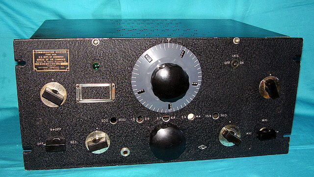
RCE  SN: 302  -  Airport Communication Receiver - Mechanical Rebuild

This restoration was more mechanical and cosmetic than it was electronic. It involved finding and installing correct vintage parts along with correcting other mechanical problems. Additionally, front panel paint "touch-up" and the mechanical approach to "body work" is covered. Further, the methods for operating a vintage receiver on "original parts" is presented.

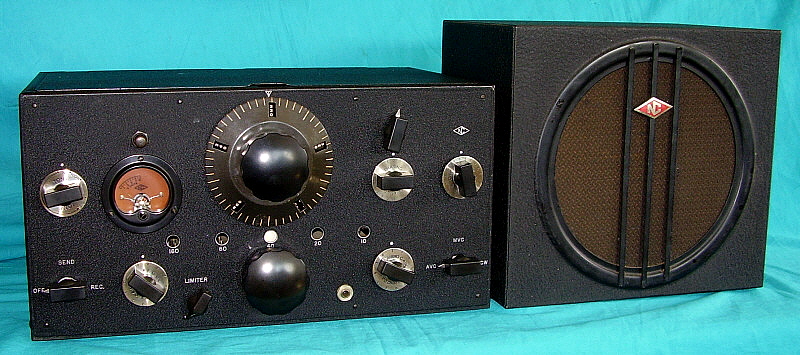
I received an e-mail from fellow Vintage Military Radio Net member WA6OPE asking if I would be interested in a National RCE Airport Receiver. He included some photos that showed the RCE to be complete but in rather "rough" condition. A deal was made and Tom brought the RCE up to the N7RCA Ham Swap Meet in Minden, Nevada (first weekend in June 2014) for delivery and payment. 
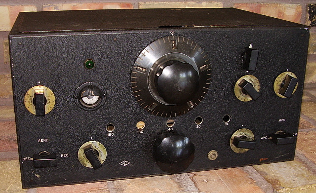
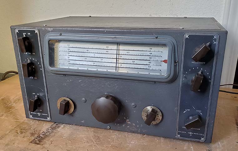
Tom had found the receiver in the SF Bay Area, apparently from a "non-ham" as the RCE had never been worked on or modified since it had been retired from commercial use. Storage in the SF Bay Area, with its salt-air environment, is problematic and long-term storage in a garage or shed can result in significant 
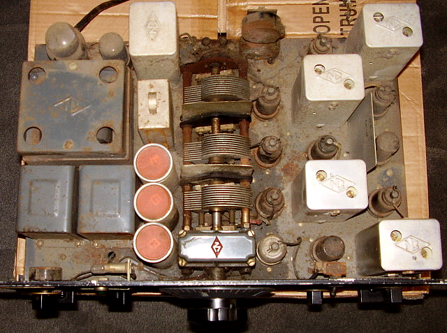
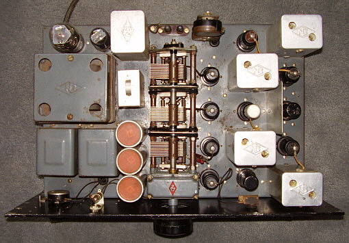
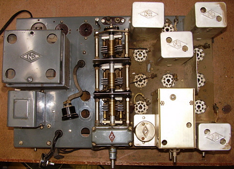
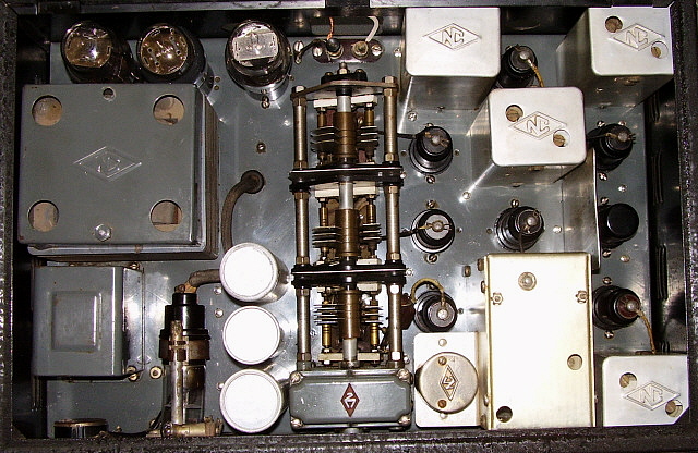
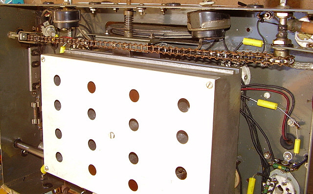
corrosion. The photo of the chassis below shows the typical surface rust that is found on metal that is stored in unheated buildings. Not terrible but certainly significant. Fortunately, the underneath of the chassis was nearly perfect which implies that condensation was probably responsible for most of the rust.

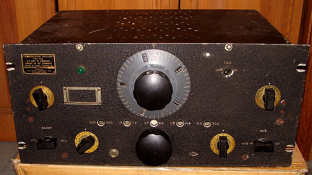
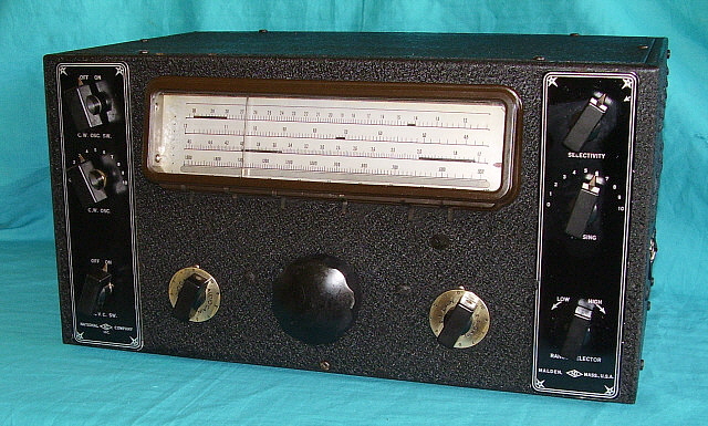
The dust cover being present is somewhat rare. It seems like many of the Airport receivers now turn up with the dust cover long-gone. This dust cover is made out of aluminum - the later Airport receiver dust covers were made out of steel. The condition of the dust cover is very good but somewhat bent in the back because the rear screws weren't installed. >>>

photo right: The RCE exterior as received before any cleaning by me. The exterior had been wiped down.

>>>  The knobs are correct but it's odd that the RF Gain, Audio Gain and CW Osc knobs are long-boss versions and the Tone is a short-boss type. The knobs appear to have the same patina and probably are original. This implies that National inter-mixed the knob styles on production. This seems normal for National and the fact the the difference is hardly noticeable further convinces me that the knobs are all original.

UPDATE - July 21, 2014 -  Someone in the past "forced" the PW-D to turn when the tuning condenser or part of the gear box was "frozen." This stripped the main condenser drive gear and the right side reduction gear of several teeth and deformed both gears. The end result was although the PW-D appeared to rotate it only did so for about one turn and then "locked up" due to the deformed gear teeth. Fortunately, I had a few extra gear boxes and I thought that a gear box replacement would fix the problem. However, the original gear box shaft is designed to fit the tuning condenser shaft that is about .375" in diameter. The "after-market" gear boxes were the type National sold for projects and were designed to fit a .250" shaft. Additionally, the original gear box output shaft was "pinned" to the tuning condenser shaft. Needless to say, the two types of gear boxes weren't directly interchangeable.

As I thought about this project, it seemed like the way to go was to find a complete NC-100 gearbox and tuning condenser assembly. That would solve the severe rust problem on this tuning condenser and would solve the broken gearbox problem too. About a nine months later (April 2015,) I was able to purchase a complete NC-100 N-PW gearbox with the three gang tuning condenser assembly attached. Also, included was a good condition PW-D. Thanks to George W7HDL.
     
photo left: The RCE interior before any cleaning. Includes lots of spider webs, rust, grease and dust.

Tuning Capacitor Transplant  - May 31, 2015 - This operation required removal of the front panel which is easily accomplished. With as much corrosion present, it was quite a surprise that the PW-D wasn't a problem to remove. The BFO knob required some light oil and heat to break its set screw loose but all other knobs came off easily. I gave the chassis a quick cleaning and although there are quite a lot of small rust pits, it's not so bad that the chassis needs repainting. Cleaning has really helped the overall appearance (see photo below.)

The first thing to do in the removal of the old tuning capacitor is to desolder the seven TC (tinned copper wire) connections at the solder lugs on the tuning capacitor. The lugs aren't difficult to access if you have a small soldering iron ( I use a 25W Weller.) National didn't wrap the TC wire connections probably because they knew if removal became necessary it would be difficult to "unwrap" the connections. Luckily, the TC wires just slide out when the solder is molten. The LO grid leak is on a tie point that is soldered to the stator lug. Just desolder the entire tie point from the stator lug. Once the seven connections are off, the capacitor can be dismounted by removing the mounting screws.

The tuning capacitor has four screws under the chassis that mount the gear box. These need to be removed. You have to move the catacomb from one end to the other to access all of the screws. There is also a bracket at the rear of the tuning capacitor. Remove the chassis screw and leave the bracket mounted to the capacitor (for now.) At this point you should be able to lift the capacitor/gear box assembly off of the chassis. This reveals the tray under the capacitor that has the three insulator blocks with the terminal connections exposed. This area will probably be very dirty and filled with all sorts of solder bits, wire ends, dust and grease - mine was (see photo right.) Clean the tray area using Q-tips to clean the insulator blocks and hard to access areas of the tray. I use WD-40 as a degreaser followed with Glass Plus to remove the WD-40 residue.

Be sure the seven lugs on the replacement tuning capacitor are tinned and the holes are fully open. On the terminal blocks, you'll note that there are three short wires and three longer wires plus the wire that has the LO grid leak. The short wires connect to the stators and the long wires connect to the rotors. You have to route the longer wires with a slight bend under the stators and then up to the rotor lugs. Originally, these wires were not sleeved but, if you are worried, you can sleeve them since sleeving was used on some of the later Moving Coil receivers. Guide the TC wires into place as you lower the replacement capacitor into place. You will need a slotted soldering aid tool and long thin needle-nose pliers to guide the TC wire through the holes in the soldering lugs. 

Once you've soldered the seven wires you can then mount the gear box and the bracket. If your replacement capacitor doesn't have the bracket (mine didn't) use the bracket from the original capacitor. After the capacitor is mounted, disengage the catacomb (place between bands) and check with an ohm meter if you have any shorts from the stators to chassis. Check rotor to stator which should also not have any shorts. Mount the PW-D and check operation of the entire assembly. No problems should be encountered.

photo above: This is a shot of the tray under the tuning capacitor of the RCE with the tuning cap removed. Note the dirt and grease that collects in this area. If you don't need to remove the tuning cap, this area can be cleaned with Q-tips and small long paint brushes. With the cap out though, the area is easy to clean.

Note the TC wire. On each block, the terminal to the left is the stator connection and uses a short length wire. The remaining longer TC wires connect to the rotor lugs. When mounting the replacement cap, you'll have to guide these wires into place as you lower the cap into place. It sounds difficult but it just takes a little patience and good illumination. Be sure to solder the TC connections first and then install the screws to mount the gear box and bracket.

Note the corrosion on the chassis. While a perfect condition chassis would be great, sometimes we have to accept that some receivers were located in humid areas and stored in sheds or unsealed garages. This corrosion is not bad enough for a repaint and most will be hidden once all of the parts are reinstalled. Some minor "touch-up" painting will also be required.

Front Panel Restoration - The front panel on the RCE was bent and had several nicks to the black wrinkle paint. The panel needed to be straightened out first.  I "eyeball" down the edges to see where the bends are. The panel is then placed on a large pine board that is perfectly flat (well, as flat as wood is going to be.) I then use two inch square oak wooden blocks about four inches long and a weighted hammer to gently bend the panel into proper alignment. If carefully done, the result will be a straightened panel with no damage to the paint. More delicate types of paint will require paper or cloth be placed on the pine board for additional protection but old wrinkle finish is tough and quite resistant to scratching or chipping and can be placed directly on the pine board.

After the panel is straight I clean it with Glass Plus. I then use nitrocellulose black lacquer that has been thinned down (~ 3 to 1) with lacquer thinner. I use this paint to touch up any significant nicks or scratches. Of course, when the "touching up" is finished, the panel paint looks uneven and spotted. The next step is to use several cotton pads - the round 2" diameter flat pads work best. Wearing nitrile gloves, dab the cotton pad with thinned black lacquer and rub the entire panel to even out the finish. Don't saturate the engraving but don't be too worried if some of the engraving is darkened by the thinned paint. >>>

>>>  The lacquer will dry in a few minutes and then the engraving has to be "reconditioned." I don't want to scratch the metal so I use a long round wooden skewer (like you use for barbequing) that I've sharpened the end of. I use this tool to go over the engraving to remove any paint, dirt or corrosion that's in the engraving. I use a head-mounted magnifier to enhance my view of the engraved nomenclature as I'm working. The result will be nice looking engraving that doesn't look "scratched out" but just looks clean and somewhat bright.

Dust Cover Body Work - The rear panel of the dust cover was really bent up. I used the same body work method of a flat pine board and oak wooden blocks with a weighted hammer to straighten the panel. The rest of the dust cover just needed a little "tweaking" to get all sides and corners square. The back of the dust cover was pretty scratched and the top wasn't much better. Sides were okay. I decided to give the dust cover a light coat of "Satin Black" paint to even out it's overall appearance.

Chassis Cleaning - Since there was quite a bit of surface rust I first cleaned the chassis with WD-40. This removes all of the grease and most of the dirt. I tried some different methods on the rust spots but found that the best results were to use WD-40 and lightly rub with 0000 steel wool. This reduces the rust spots to a minimum and doesn't hurt the chassis paint. Don't be too aggressive though. Lightly use the steel wool. Avoid the ink-stamped tube identifications as the steel wool will remove these. Next, wash the chassis with Glass Plus and a paper towel. You can somewhat "polish" the paint with the paper towels. This gets the chassis paint looking about as good as it can.  The aluminum cans were slightly pitted under the dirt. I lightly removed the dirt with WD-40 applied with a cotton cloth. Use a circular motion to avoid streaking of the cleaning action. Don't rub too hard or you'll polish the aluminum which then doesn't look original. Lightly clean the WD-40 with Glass Plus. The end result should look flat matte finish that is clean. The audio output transformer was the worst condition and really didn't respond to much cleaning but the IF cans turned out quite nice.
Bar Knob Skirts - The procedure to clean these solid German Silver skirts is in the section "Detailing the NC-101X" further down this page. Essentially, NaOH (Easy-Off Oven Cleaner) is used to remove corrosion and grunge. Then the knob is washed in water to remove the NaOH and cleaned with Glass Plus. Then the skirt is polished with Wenol's. The skirts are the same material all the way through so this method works great.

photo left
:  The RCE chassis after cleaning and installation of the replacement tuning condenser and gear box. Although the chassis paint isn't perfect, it's not too bad. The aluminum cans turned out matte finish after cleaning.
PW-D Repaint - The original PW-D was "lumpy" with corrosion under the paint. This is difficult to remove since the base metal is damaged. I decided to just use another PW-D that was in better condition but still needed a repaint. The Airport receivers used a light-gray paint on the Index dial and then black with white numbers on the Number dial. I had an excellent condition gray PW-D that was on my RCF-2 receiver. This was used to "match" some automotive lacquer paint from All Auto Paints in Carson City. They will do the match and then fill a spray can with the paint for $18.

The old paint has to be removed from the Index dial. This can be accomplished with Jasco Epoxy Stripper (methylene chloride - so do it outside using Platex outer gloves and nitrile inner gloves.) Clean with steel wool and alcohol and then clean the Index dial with lacquer thinner afterwards. This prep is enough to then apply the lacquer without any primer (that's the way the originals were painted.) Don't spray more than two coats since modern auto paint has some fillers in it which might "fill" the index lines too much. Two coats should be enough. Let the paint set overnight. Then use a mixture Artist's Acrylic paint of white and raw sienna to create a manila color (beige color) to fill the index lines. Don't use pure white - it will look way too bright. Apply the manila paint a few index lines at a time (five to ten works well.) Let the paint set for one minute and then wipe off with a damp paper towel piece (dampened with Glass Plus works best.) You might have to do two applications of paint to get a really good looking fill. Let the index lines dry for a day. Wipe the Index dial with a cotton cloth. Reassemble the PW-D if the Number dial is is good shape.

Initial Testing - Since the commercial and military versions of the NC-100 receivers use oil-filled paper dielectric filter capacitors, frequently they can be operated with all original parts. I really wasn't planning on using the RCE as a station receiver and the set would only be powered up for testing and maybe a casual listen around the bands. When long-term use is planned (like the NC-100ASD or the NC-200 profiled above) it is necessary that all paper-wax capacitors be replaced since their leakage current is only going to get worse as the receiver is operated. But, I felt that the RCE could be safely operated with all of the original components if the filter capacitors tested okay. I just checked these parts for shorts and for value and found them to be okay. Before power-up, it's a good idea to just check the DCR of the B+ to chassis. It should be very high resistance which would indicate that there are no "power-off" shorts to chassis.

Upon power-up, I watch the rectifier tube carefully. If there is a short or other type of excessive load on the B+, the rectifier tube will glow bluish-purple inside the filament to plate area. If the rectifier appears normal, then B+ should come up to voltage in about 20 seconds or so. I measure it to be sure it's in spec and not loaded down. I watch for any indications of sudden heating which would indicate a heavy current flow through a resistor due to a shorted or nearly shorted bypass capacitor. Luckily, none of these things happened and the RCE powered up fine and did work somewhat. Of course, since I had replaced the tuning capacitor, it was pretty much out-of-alignment but still a few AM BC stations could be tuned in which let me know the receiver basically was operational. I performed an IF alignment and found that was pretty close. The RF tracking was way out, as expected. I kept having trouble with the contacts of the catacomb with the receiver on its side (necessary for RF tracking alignment.) The catacomb had to come out for further checking of the pins and receiving contacts. Mechanically, the catacomb seemed to be "flexing" the chassis when bands were changed which also warranted a thorough inspection.

Catacomb Movement Issues - The catacomb problem was due to some corrosion spots here and there on the shaft. These were removed with 600 grit Alu-Oxide paper and oil. The bearings in the catacomb were also oiled. The flexing of the chassis was due to the shaft mounting screws not being fully tightened. The front bearing for the pinion gear needed another spacer to be added to have the rack and pinion gears fully mesh and to have the shaft bearing fully within the catacomb slot. A light coating of grease was applied to both the shaft and to the rack.

On the pins and split-contacts, they were of course dry which increased the force necessary to have all fifteen pins to engage the contacts. Originally clean grease was applied to the pins although nowadays this has dried up or has turned into a "dirt-trap." I cleaned all of the pins and split-contacts with DeOxit and Q-tips, reapplied new clean grease (very light coating) and then reassembled. The bandswitching was now a fairly light action and there was no more flexing of the chassis.

Back to Aligning the RF Tracking - The LO kept dropping out at the low end of the bands on bands A, B and C. Bands D and H seemed okay. The entire operation was somewhat erratic. I checked the connections to the tuning condenser. I found that during soldering of the TC connections I had not soldered the lower TC wire to the LO stator. The wire was thru the hole in the lug but just not soldered. This was enough for the LO to not operate correctly on the higher frequencies. Soldering the TC wire corrected the problem and the alignment was completed on all bands. 

Final Testing - Since the RCE was operating on all original paper capacitors, I was particularly careful about checking the heat build-up in the power transformer. This is a crude method of determining how much of a load there is on the B+ due to leaking capacitors (one can also measure the current draw of the B+ - it should be around 70mA nominal.) During an alignment, the receiver is going to be in operation for at least a half-hour. Checking the power transformer and the chokes several times for heat, I was surprised that nothing got hot. Again, I would stress though,...I'm not planning on operating the RCE for extended periods of time. If I was going to do that then it would be almost mandatory that the paper caps be replaced. For short test periods, original parts are okay if they not defective (other than the expected minor leakage current.)

Performance - I'm quite surprised that this RCE actually works better than my much nicer condition RCF-2. I guess that goes to show that appearances can be deceiving. Anyway, the RCE now looks pretty good but how does it perform?

I used a 7000Z ohm to 8Z ohm transformer on a 10" speaker that is mounted in the larger style National speaker housing for the RCE. When I tested the RCF-2, I had used a military LS-3 speaker that had a 600Z ohm transformer installed. However, the DCR of the output transformer on the RCE measures 280 ohms which seems too high for a 600Z ohm output which would normally be around 50 to 100 ohms DCR. The 7K set-up seemed to provide a normal reproduction level. AVC has a rather slow attack, probably a capacitor problem. Sensitivity is respectable with 40M ham signals coming in strong. I tried 20M and also heard a few hams there. The surprise was 11M CB with many strong AM signals in that region of the spectrum. No ham 10M sigs were heard. The AM BC signals (above 1300kc) were strong but the audio not very good. The DGPS nodes around 300kc were quite strong on band H. I didn't hear any NDBs because I was testing performance during the daytime.

I'm sure that if I went ahead an did a full "re-cap" and replaced any "drifting" resistors followed by another complete alignment, the RCE would be a really great performer,... when compared to other similar pre-WWII receivers.


Detailing the NC-101X Receiver

Many times the receivers we find don't really require a total restoration or rebuild. Sometimes only a little cleaning and repair of a few minor problems will result in a usable receiver that is performing quite well. I call this "detailing" a receiver. Mainly a cosmetic job with only a little electronic work necessary. Here's how we did this type of task on a NC-101X receiver recently.

Initial Inspection - I bought this NC-101X from an ad on QTH.com with only the photos and description to go by. Dave N7RK was very accurate in both departments and his packing job was first rate. The NC-101X arrived with no damage. It is shown in "as acquired" condition in the photo to the left. An inspection found that the receiver was as described,...very nice external condition with just a few blemishes and dirty but mostly complete on the inside. The dirt was a dusty type with some grease and maybe some tobacco deposits mixed in. This "dirt" made a very good preservative for the gray paint used on the chassis. Dave had said the receiver worked so I wasn't shy about just "going for it" and applying power. Although the NC-101X did function it had some hum problems. Removing the bottom cover revealed that the dual electrolytic was disconnected. I figured this was probably for a reason and decided to replace the filter caps before going any further.

I mounted the three 10uf filter caps under the chassis. Since all of the original paper caps had been replaced several decades ago with Sprague molded capacitors (not Black Beauties but the later versions with a black plastic body with red nomenclature) I felt these were probably okay. Upon power up the NC-101X now seemed to work fairly well.

I hadn't tested any of the tubes and really hadn't done much of anything other than confirm that the receiver did function and all of the major parts of the set worked fine. All that was now necessary was detailing the cosmetics and a complete servicing of the electronics.


Chassis Inspection: The chassis "as received" is shown in the photo to the right. The dirt is obvious and as mentioned above actually acted as a preservative for the paint. The first thing noticed is that only one can-type electrolytic capacitor is present. Although it is very similar to the originals, it actually isn't an original type. The original filters were all 10uf 450wvdc individual capacitors. The one installed is a dual capacitor which is not correct.

The next thing noticeable is that the power transformer appears rather tall. A quick look under the chassis showed that the power transformer was indeed marked "NC-100" but the complete ink stamp was "NC-100-25" which indicated that this transformer was for 25 cycle AC. All power transformers for 25 cycle operation will have extra laminations installed to increase the iron and prevent over-heating on such a low frequency AC. Operating a 25 cycle transformer on 60 cycles will cause no problems and many so-called 25 cycle transformers are actually rated "25 to 60 cycles."

The tuning condenser appeared to be slightly rusty however this wasn't the case. What appeared to be rust was actually greasy dirt probably mixed with tobacco smoke that turned the metal pieces a rusty color. The rotor hubs are brass but it's difficult to tell through the dirt.

The tuning seemed to work fine so that indicated that the gear box probably only needed to be cleaned and lubricated.

I was lucky that nobody had tried to clean the aluminum IF transformer cans and BFO can. Improper cleaning of this soft aluminum will end up polishing the matte finish.

Under the Chassis -  This area had been recapped several years ago using Sprague black plastic molded capacitors (with red nomenclature - not Black Beauties.) The installation appeared to be a professional job with all of the capacitors matching in manufacturer and type used. Soldering appeared professional. Many hams WERE professionals in the electronics business besides being hams. All of the resistors were Centralab types that National had changed over to by 1937. These Centralab resistors are excellent in quality with carbon drifting almost never being encountered. Cosmetic Inspection - The NC-101X only had some minor blemishes to the original black wrinkle finish. The skirted knobs were very dirty with tobacco deposits and some tarnish. The PW-D dial, while in pretty nice original condition, did show some wear especially at the point where the Index dial angles off. Here the paint was worn through to the metal. There were no gouges or scratches as is normally found on poor condition PW-D dials. There were no extra holes drilled anywhere on the chassis or the cabinet.
Getting the NC-101X Operational - This isn't restoring, it's just getting the receiver to a point where I could use it and do some evaluation of its performance. The new filters got the NC-101X running with no hum. The receiver came with 6V6 tubes installed in the audio output. Original tubes were 6F6 and while you can substitute the 6V6 and it will draw only 2 amps of heater current versus the 3 amps required for the 6F6, there are internal structural differences between the two tube types. The 6V6 is a beam-power pentode while the 6F6 is a regular pentode. To some ears, the 6V6 will sound a bit harsh compared to the 6F6 if the circuit and transformers were designed for 6F6 tubes. This was the case with the NC-101X, the 6F6 tubes sound a little bit mellower and slightly more bassy - at least with the original 10" Rola electrodynamic speaker.

At this point the NC-101X was performing well enough to try using it as a station receiver. I used it on both 80M and on 40M on the AM nets available on those bands. The NC-101X was surprisingly effective as a station receiver. Sensitivity was ample although successful 80M or 40M reception doesn't require too much of a receiver anyway. The important thing was how the receiver sounded and how immune to adjacent SSB activity it would be. Performance was good enough that I decided to proceed and do the complete "detailing" followed by a complete IF/RF alignment.

Disassembly - Without removing the cabinet it's next to impossible to access all of the areas of the chassis for complete cleaning. The cabinet is easy to remove. First, remove all of the tubes. Then take off all of the knobs. Then note that the RF Gain control is mounted to the front panel as is the Tone Control. Remove the mounting nuts on these two controls. Remove the mounting nut for the phone jack assembly. Dismount the pilot lamp assembly. Remove the back cover and lid assembly by removing eight mounting screws. Now remove the four large screws, nuts and lock washers that mount the cabinet and front panel assembly to the chassis. The cabinet and front panel assembly should now slide forward to clear the control shafts and then can be lifted off. Cabinet removal exposes all of the chassis and chassis mounted components for thorough cleaning. Cleaning the Chassis - As mentioned, the dirt and grunge was a dust combined with grease and tobacco deposits. Since grease was involved I used WD-40 as a cleaner. WD-40 generally will not react with older types of paint, which in this case was lacquer. The dirt and grunge came off very easily and left the chassis paint clean and having somewhat of a shine. The application of the WD-40 was with a medium size paint brush and sometimes Q-tips when the area was too small for the brush. Paper towel strips were used for WD-40 removal. This was followed by another cleaning using Glass Plus to remove the WD-40 residue. Glass Plus doesn't contain ammonia and won't react with painted surfaces (don't use Windex.) The ceramic tube sockets were cleaned with De-Oxit and a clean tooth brush and wiped down with a paper towel strip. As expected, the grunge had acted as a paint preservative and the chassis turned out to be in excellent condition.
Cleaning the Tuning Condenser - Again, WD-40 was used as a cleaning agent due to the greasy nature of the grunge. Small paint brushes and Q-tips were used for the most part. The nickel plated spacers were cleaned with a brass tooth brush (brass won't scratch the Nickel plating) and WD-40 which removed the discoloration completely. The ceramic spacers had to be cleaned with Q-tips. After all of the grunge was removed, the tuning condenser was further cleaned using Glass Plus to remove the WD-40 residue. Paper towel strips or Q-tips were used to remove excess Glass Plus. After the tuning condenser had time to dry (overnight) it was lubricated with DeOxit on the rotor contacts and 10W oil on the bearings.

Cleaning Under the Tuning Condenser - This area seems to really attract dirt. I didn't want to remove the tuning condenser so I used long handled small paint brushes and bent Q-tips to clean this area with WD-40 followed by Glass Plus. You have to fit the brushes and Q-tips under and sometimes through the tuning condenser. 

Photo Right: This shows the chassis after half of it has been cleaned with WD-40 and Glass Plus. The tuning condenser has also been cleaned in this shot. Note that the three electrolytics were removed for cleaning. Actually, two were missing and the third wasn't original and wasn't connected up anyway. With the electrolytics out of the way, cleaning is easy around the tuning condenser and reinstallation of these capacitors is not difficult. I didn't do any polishing of the chassis paint. This is how certain kinds of dirt and grunge end up protecting the original paint finish. The WD-40 cuts through the grease and removes it and the associated dirt. Then the Glass Plus is used to remove the WD-40 residue.

The PW-D - The original PW-D had a badly worn Number Dial that "chattered" if the dial was turned too fast. Even lubricating the elliptic hub didn't stop the "chattering." I swapped another Number Dial to correct the problem temporarily. The Index Dial was in pretty good shape with no scratches but the paint was worn through around the tuning knob. Eventually, I wanted to find a good condition replacement. It ended up I didn't have to wait all that long. A couple of weeks after acquiring the NC-101X, I was at the annual Minden, Nevada swap meet put on by N7RCA. What should turn up but an excellent condition PW-D in a protective plastic bag - nice. The paint was very close to the original NC-101X's PW-D in that it was the dark bronze-black shading even though the new PW-D was actually a WWII vintage piece. All the new PW-D needed was to be disassembled, cleaned, lubricated and reassembled to end up functioning perfectly - and looking incredibly nice. Cleaning the Skirted Knobs - The knobs on this NC-101X were the early style knobs with the short boss on the bakelite bar knob section. These knobs were advertised by National as having skirts that were "solid German Silver." German Silver is an alloy of Nickel, Copper and Zinc that generally is used in plating but also can be used as a solid metal alloy. In this case, the metal is the same all the way through so it can be polished heavily without wearing through any plating. The skirts on these knobs were pretty tarnished and I initially cleaned off the oxidation, tobacco deposits and grunge by carefully using NaOH (Sodium Hydroxide) commonly found in Easy Off Oven Cleaner. Using a small paint brush, I carefully painted some EOOC (that I had sprayed into a paper cup) on the skirt. Be sure to avoid getting EOOC on the bakelite bar knob. Work the EOOC around on the skirt and then rinse under cold water. This will remove all crud and oxidation. Follow this by polishing the skirt and the bar knob with Wenol's Polish (similar to Semichrome.) Since the skirt on these early knobs is solid German Silver, the polishing works great and if the EOOC has removed any of the nomenclature fill, the polishing residue is "jet black" and ends up filling the nomenclature perfectly.
The Can Electrolytic Capacitors - This wasn't going to be one of my "museum quality" restorations where I restuffed caps and made the chassis look totally original both on top and underneath. Since it had been professionally recapped in the past with excellent components and workmanship, I decided to leave the underneath "as-is." I had already connected three new 10uf 450wvdc electrolytic capacitors under the chassis so the receiver was functional. I did want the top of the chassis to look correct however. So, I dug through the "junk boxes" until I found three close matching can electrolytics. These had to not only match each other but had to be similar to what was originally in the NC-101X. Luckily, I was able to come up with three good candidates. Since these were dummy-cans, I removed the wires from the bottom of the can. I also repainted to top silver (although some NC-100s are found with red or brown tops.) When mounted, everything looked convincing correct. Now, anytime in the future, if I want to do a "museum quality" restoration, these cans can be rebuilt into functional components.

Photo Right: This shows the NC-101X chassis top after detailing. This is after the painted surfaces have been given the final cleaning with Glass Plus and polished with a soft paper towel. Note that tuning condenser hubs now look like they should - brass. Also, the nickel plated spacers look like nickel. Don't get too aggressive when cleaning the tops of the IF transformers, the top of the BFO can or the interstage transformer can. These aluminum cans are pretty soft and will "polish" quickly if cleaned or rubbed aggressively. Use WD-40 first with a soft brush to gently remove any grunge then follow with Glass Plus. Dab with a soft cloth to dry - don't rub. This should leave the cans appearing as a matte aluminum finish - as original.

Cabinet Detailing - The cabinet pieces were in very good condition and only required a little touch up painting. I use Artist's Acrylic Mars Black for most touch ups but sometimes I also will use nitrocellulose jet black lacquer thinned and applied with a small brush. It depends on the blemish. In this case, the inner surface of the cabinet where it contacted the chassis had some surface rust. Cleaning this up removed the original black paint (which was lacquer.) This was touched up with the lacquer. The wrinkle finish blemishes were touched up with the acrylic paint applied with a small brush or Q-tip. Front Panel Detailing - The front panel was in very good condition and only required cleaning and touch up. I used Glass Plus applied with a 2" paint brush and then the Glass Plus was worked into the panel using the paint brush. After a couple of minutes cleaning the dirty residue was wiped off with a paper towel. Then a second spray down with Glass Plus and wipe down with a clean paper towel. This gentle cleaning will usually get most of the grunge off. I then touched up the panel and let the acrylic dry overnight. The next day I used Armor-All to polish the panel and also gave the cabinet the same treatment. If I was doing this today (2016) I'd use 10W machine oil instead of Armor-All. I find the results less harsh-looking.
Reassembly and Test - About the only thing to mention on reassembly is to be sure to set the PW-D correctly as described in the section "PW-D Micrometer Dial Servicing." Basically, you have to set the tuning condenser to "half mesh" and then install the PW-D which will be set to "250." When installed correctly you should be able to cover 0 to 500 with an overlap on each end that is around 10 divisions.

Alignment - The IF is aligned first and you have to determine the frequency of the crystal that's installed in the crystal filter. Using this exact frequency in your IF alignment will assure that the crystal filter is a useful tool for combating QRM. Switch on the crystal filter and adjust the Selectivity and Phasing controls for a narrow bandwidth. With the RF signal generator connected to the grid of the mixer tube, sweep the generator frequency through 456kc and listen for a peaking noise as you pass the crystal's frequency. With a digital frequency counter connected to the RF signal generator note the exact frequency that the crystal responds to. This will be the IF used for alignment. In my case, the crystal was 456kc. Adjust the IF capacitors for a peak indication using the "eye-tube." You can also connect a VTVM up to the AVC line and monitor that voltage for alignment purposes. Be sure to use a 400 hz modulated signal on your RF generator and have the receiver in AVC.

The RF tracking alignment requires the receiver to be on its side with access to the coil catacomb. Generally, the inductance which adjusts the lower end of the band was set at the factory and shouldn't change unless there's severe environmental problems with the storage that allowed moisture to ingress into the coils. Most of the time the catacombs are sealed pretty well and are protected by their location under the chassis. Usually, only the trimmer capacitors needs to be adjusted for each band. Connect the RF signal generator to the Antenna Input and use a 300 ohm load (a 300 ohm carbon resistor in series with the input.) You'll have to reference your NC-101X calibration charts for each band since these provide the frequencies that should be used at 450 on the PW-D for the high end and 50 for the low end of each band. Set the PW-D at 450 and the proper frequency input on the RF signal generator. You'll probably find that the LO is pretty close but tweak it in at the exact frequency. >>>

>>>  Now check the tracking by tuning down to the low end (PW-D at 50 and the correct input frequency from the signal generator) and you'll probably find it is very close. Return to 450 and the correct input frequency and set the Mixer and the RF stages for peak. You can measure the AVC voltage or you can use the "eye-tube" for a peak indicator. I just used the "eye-tube." Perform this same procedure on each band. Be careful on the 10M band as it is very easy to align to an image. With only one RF amplifier stage the image ratio isn't all that great on 10M so keep the RF generator amplitude as low as possible and check your LO tracking carefully. If you align to an image the tracking will not be accurate. You can also align the Mixer stage to an image and this would show up as uneven gain across the 10M band. Usually if you keep the RF input as low as possible and adjust for the strongest peak that will be the correct setting.

photo above: The NC-101X SN: 181-G after detailing

Performance - I'm impressed by the NC-101X. It's certainly sensitive enough on 80M and 40M. I've listened on 20M and it seems to do very well on that band too. I haven't tried 10M but I think it would also be adequate there. Certainly, if 10M performance was an issue, an external RF Preselector could be added. IF bandwidth is probably about 8kc without the Crystal Filter. QRM hasn't been a problem but I'm sure the Crystal Filter would be able to eliminate all but on-frequency interference. The audio is really nice. I'm using the matching 10" Rola electrodynamic speaker that came installed in the larger National speaker box. This seems to reproduce AM signals quite well and there is quite a bit of bass in some signals. The Tone control is not very responsive and does most of its action in the last 10% of rotation. On the station antenna, which is a 135 foot center-fed tuned inverted vee, the signals on 80M are so strong that I have to reduce the RF gain to about 7, even with the AVC on. This is to get the "eye-tube" to show some reaction since with the RF gain at full the eye-tube will always remain closed. Since my use of the NC-101X has been on 80M and 40M AM, I haven't noticed all that much drift. The bandspread action of the NC-101X will make drift show up more since a slight drift of a few kc would be indicated with as many as 8 or 10 divisions on the PW-D. The most drift I've noticed is about three divisions over an entire net time (about an hour.) Remember though, this is in the AM mode. Of course if you're monitoring a SSB net or doing CW, the drift in the BFO will also be a factor and more drift will probably be noticeable. Overall, I'm impressed enough with the NC-101X that I've set it up with the Collins 32V-2 transmitter and have been using it as the station receiver (off and on) for several weeks now. Using the Eye-Tube - I've been using the NC-101X as a station receiver for a while now. I've found that for AM on either 80M or 40M, I can't really run the RF gain "wide open" (receiving on the station antenna) and have the eye-tube show anything other than fully closed. Backing the RF gain down is necessary and provides some interesting possibilities. I've been listening to the AM "round-table" stations and adjusting the RF gain to have the eye-tube fully closed on the strongest station. This usually has the RF gain set at about 7 or 8. Now all of the other stations are normally going to show something less than fully closed on the eye-tube when they transmit. After a couple of sessions you get to where you can sort of estimate signal strength relative to the strongest station. It might have been something that the original owners of early NC-101X receivers did - at least if they operated AM.
 

Detailing the NC-80X Receiver

This isn't a restoration write-up. It's detailing a receiver that had already been recapped but was not completed as far as mechanics and assembly. Also, this write-up provides a way to present more detailed information on this "seldom-encountered" receiver, including photos of the chain drive assembly for moving the catacomb.

I had been seeing this NC-80X being offered for sale for awhile. I was interested but, as usual, I was distracted away from an actual purchase many times. Eventually, I had to contact N7RK and work out  how to purchase this NC-80X. As always, Dave provided excellent photos and I knew in advance what I was getting into as a project. Packing and shipping from Arizona was first class all the way. As described, the receiver was already recapped but had bad filter caps and some of the dial bezel and dial lamp assembly was still apart. The first step though was complete disassembly for a thorough clean up.
Disassembly - The cabinet is held together with sheet metal screws. The front and sides are one sheet metal piece. The back is one sheet metal piece. The top and bottom are sheet metal pieces. The only unusual feature is the eleven screws and shoulder-nuts that isolate the chassis from the cabinet.

Serial Number - I looked and looked for the serial number on this NC-80X. Most National receivers have the serial number stamped into the chassis but not the NC-80X. Complete cleaning and some disassembly proved to me that there wasn't a serial number anywhere on the chassis. Sometime into the project, I was thinking, "I wonder if National stamped the cabinet instead." Looking at the back panel in the proper light and there it was,...stamped just below the opening for the headphone jack,...C 475. Difficult to see since the black wrinkle paint was applied after the stamping of the serial number.

The Bezel and the Station Markers - The bezel was brown plastic and there were six curved metal clips that were inserted into a lengthwise slot at the bottom of the bezel. What did these clips do? At first I thought it was some sort of mechanical method to mount the bezel - it wasn't. Looking at the advertising artwork, I could see that the points of the clips were next to dial scale. By reverse-mounting the clips, they then revealed their purpose - they were station indicators. The clips have a portion that protrudes out the bottom slot and one can then grab this "tab" and slide the clip in its slot until the "pointer" is aligned with where your favorite station was located on the dial.

The bezel was missing its clear plastic dial cover. I assume it was plastic because whatever was original was held in place with drive pins. I think glass would have broken when the drive pins were installed but plastic would work fine. I used .030" thick clear plastic cut to fit and mounted with Duco cement. Only one drive pin was present so the Duco cement was an option that worked fine.

Catacomb Chain Drive System - The small coil catacomb of the NC-80X only requires a chain drive to move it into position for the four bands. The catacomb seemed to be locked in place so it was disassembled. There wasn't anything wrong but, as with the NC-80X's big brother the NC-100, the pins and the receiving contacts must be clean and the rod bearing must be lubricated for smooth, easy operation of the band switching system. There are only 10 pins to engage (rather than the 15 pins on the NC-100) so the chain drive is adequate for moving the catacomb into position. Thorough cleaning got everything working smoothly.

Coil Assemblies - These are identified as W, X, Y and Z for frequency coverage and 1 for Mixer function and 2 for Local Oscillator function. They mount in the same manner as the NC-100 coil assemblies. Since the IF is 1560kc, these coils are different than the NC-100 series coils.

Chassis Cleaning - The chassis was cleaned as described in the NC-101X write-up above. I use WD-40 to cut the grease and Glass Plus to clean up the residue. This chassis had mostly soot deposits - weird. Anyway, they cleaned up with just the Glass Plus. Complete disassembly allows for a thorough cleaning job.


photo right: The smaller-than-usual coil catacomb showing the chain drive system.

Cabinet - Four pieces comprise the cabinet. The rear panel, the front/sides piece, the top and the bottom. All pieces were cleaned and then touched-up with black nitrocellulose lacquer. Afterward the pieces were rubbed down with 10W machine oil (this does work great - better than ArmorAll.) The two nomenclature panels are held in place with the control mounting hardware so their removal and reinstallation is very easy. The "ground wire" lug for the wire for the antenna input coil return is riveted to the cabinet. This was missing and a new lug, wire and spade lug needed to be installed.

Bezel Mounting - The bezel can only be mounted or dismounted after the cabinet has been taken off of the chassis. This allows access to the back side of the front panel. Four 6-32 screws hold the bezel in place. They screw in from the inside of the bezel behind the clear dial cover. A gasket is needed so the bezel will mount "tight" against the cabinet. I used a thin piece of friction tape to make a gasket that accomplished the proper spacing.

Loud Speaker - The NC-80X doesn't have an internal audio output transformer. The pin jacks connect to B+ and to the 25L6 plate. The speaker that was intended for use with the NC-80X was the standard National 8" table speaker that used a PM speaker with an audio output transformer mounted on the speaker. This is the same speaker used with the HRO Senior. Primary impedance is about 7000Z and the secondary is 8.0Z.

photo left: This shows the "favorite station" marker clips and how they can slide along the slot in the bezel

Filter Capacitors - Originally the NC-80X used two 40uf 150wvdc electrolytic capacitors that mounted to the chassis via large threaded bases. The negative of each capacitor is connected to chassis (B-.) I left the original caps in place and removed their connecting wires. I mounted two Sprague 50uf 150wvdc axial mount electrolytics (yes, they were old ones from 1983.) I tested and reformed the caps before installing.

AC-DC and Chassis Isolation - Everyone knows that in a receiver with no power transformer, the circuit is directly connected to the line. B- is usually chassis but in some cases, with improper power plug orientation, the chassis can have AC voltage present. If this were also on the metal cabinet, then the operator would likely receive a line voltage shock if he was touching the cabinet and another part of his body was at ground. Realizing this possibility, all designers of AC-DC radios isolate the chassis from the metal cabinet. National did this using eleven rubber grommets and special shouldered nuts and screws to provide complete isolation of the chassis. Additionally, realizing that someone could lift the lid on the receiver and touch the chassis parts while the receiver was powered up, National didn't provide a lift-lid. Instead the lid is screw-mounted.

All of the rubber grommets were natural rubber and had disintegrated or were in that process. All grommets had to be replaced. Modern black rubber grommets were used since the brown natural rubber ones are difficult to find these days.

Pre-power-up - I tested all ten tubes used in the receiver and found that the 6B8 (amplified AVC) was weak but all other tubes tested fine. I installed a vintage power plug on the AC line cord and was ready to test the NC-80X. But wait a minute,...I didn't want to just plug this into the AC line direct. So, I had to drag out the hefty isolation transformer that I have (good for 20 amps) and actually have something between the house AC line and the NC-80X. Anyway, I was going to need the isolation transformer for the alignment since if you try to hook up test gear to an AC-DC radio there will usually be a conflict between grounds and how the radio is connected to the AC line. Best to use an isolation transformer to eliminate any problems.

Power-up - An interesting feature are the power switches that are combined with the RF and AF gain controls. The RF gain turns the Line voltage on and the AF gain control turns on the B+ voltage and also functions as a "standby" switch (by removing B+.) With power applied the NC-80X lamps didn't come on. This was just a loose lamp. The receiver came to life tuned to the broadcast band. Very good audio from the 8" National speaker. Just a 25 foot wire for an antenna. Bands W and X functioned fine and calibration was fairly close. I tuned into some 75 meter AM signals which sounded quite nice. Bands Y and Z only tuned in signals on a portion of their coverage which indicated a LO problem.

Minor Problem - There was no B+ going to the plate of the LO tube. Originally there had been a jumper between pins 3 and 4 which allowed the plate to connect to the screen for the B+ connection. For some reason the jumper was missing and installing a new jumper got the LO working on all bands correctly.

Alignment - Since the NC-80X doesn't have a TRF stage it might be possible to align the LO or the Mixer to an image, especially on the two highest frequency bands. However, this would require an extremely high level input from the signal generator. Since the IF is at 1560kc, an image would appear 3120kc lower than its actual frequency. Images are caused when an "untuned" signal gets pass a non-selective RF or Antenna stage and mixes with the LO to produce the signal at the IF. Normally the LO would be operating above the tuned signal but mixing can also take place with the LO below the received signal and that's what happens with an image. It's usually the non-tuned signal mixing with the LO below its frequency. That's why images are normally two times the IF below the actual frequency of the signal that is "leaking thru." Since the NC-80X's images are 3120kc down, the normal selectivity of the antenna coils are sufficient to practically eliminate image response.

IF alignment is straight forward except that the frequency is 1560kc. Be sure to use the actual crystal frequency for IF alignment and then your crystal filter will function correctly. You can use either an audio output level meter or use a VTVM monitoring the AVC line as a "peak" indicator.

Performance - Surprising! I was not expecting the NC-80X to be a very good performer but it has plenty of sensitivity and pulls in signals even up to 10 meters. The selectivity is via the crystal filter and it works like the HRO crystal filter in that there is a "peak" adjustment on the selectivity control that should be set, even when the crystal filter is off. I used an eight inch HRO speaker box and the audio on AM BC is very good. SW BC also sounds good on strong signals. Dial accuracy is fair and the resolution is very limited. The BFO provides a fairly stable oscillation and allows decent CW or even SSB however drift would be an issue if you wanted to monitor a SSB net over a long period of time. Drift is certainly normal for the vintage of the NC-80X and not objectionable.

The down side of the NC-80X is mechanical. The chain driven band change feels like the chassis flexes whenever it is operated. The band in use indicator is very crude and although it does its function it's basically a string and a wire spring operated device. The clips for indicating favorite stations are crude and always seems to be leaning one direction or the other. It's obvious that National put most of the cost cutting into the mechanical side of the NC-80X.

The NC-80X is a sensitive receiver that is certainly capable of functioning as a station receiver. However, the AC-DC power and some of the mechanical issues might limit its compatibility with other equipment.

NC-81X - Ham Bands only in Gray Wrinkle Finish with Brown Knobs

This short write-up is just to show that NC-81X versions were produced and some were purchased. This particular example was a "gray wrinkle finish" version fitted with brown bakelite knobs. It was moderately compromised as far as condition was concerned but the crucial "missing part" finally turned up and that allowed the receiver to at least have a "passable" appearance.

I found this example of the "Ham Bands Only" National NC-81X in the "junk receivers pile" at Ham and Hi Fi in Sparks, Nevada. As I remember, I think the price was $15 (because it was "junk.") I looked it over because the NC-80X/81X are seldom-seen versions of the Moving Coil receivers and this one had the even more scarce gray wrinkle finish paint job with brown knobs. Obvious though, was the missing dial escutcheon. These were just like the escutcheon shown above in the NC-80X write-up. It appeared that everything else was present, including the top and the bottom covers, so I made the "big purchase." I stored the receiver in the shop knowing it would be a while before an escutcheon turned up.

Well, that was probably at least six or seven years ago. I haven't been "searching" for an escutcheon but, as with most "restorers," we all know what we need for several different projects that are just awaiting for some part to show up so that the project can either be completed or at least move forward toward completion. So, I was doing the usual search on "national radio" on eBay and an escutcheon showed up. It wasn't exactly for the NC-80/81 but it was close, probably for a National NC-46. This escutcheon was metal instead of plastic. It had a glass dial cover instead of plastic. It was mounted with screws along the flange rather than screws from the backside. I took a chance that even though it was obviously for a different receiver, it would be the same size. When the escutcheon arrived, I took it out to the shop to see how it would fit and it was exactly the size as needed, so the fit was perfect. This escutcheon is painted gray and is metal. Also, it will require drilling six small holes to mount the escutcheon to the front panel.

Fitting the Escutcheon - This was very easy to do and I really just "eyeballed" the position of the escutcheon and marked the holes using a fine point Sharpie going through the holes in the escutcheon onto the front panel. This gave me very accurate markers for the center punch. I had removed all of the tubes before I did any punching or drilling. With the hole locations center punched, I drilled out each with a #58 drill bit (since the cabinet/panel is steel, a drop of machine oil on the drill bit will help the process.) This allowed using the original "hardened" screws that are somewhat "self-tapping." I installed the screws first to make sure they all would tap their holes and I used a drop of machine oil to ease the "thread cutting" action since the panel is steel. Then I removed the screws and mounted the escutcheon using the same screws.

Once the escutcheon was mounted, it almost looked like it was an original piece. The gray color matched the gray wrinkle finish and made fact that this escutcheon is for a NC-46 not very obvious, except to NC-80X/81X experts. 

Under Chassis Inspection - All paper-wax capacitors were present and looked like the original caps. The electrolytic filter capacitors had been replaced years ago using chassis mount can types. The catacomb chain system seemed to work just fine. The isolation transformer isn't the National type that could use the eyelets provided, so the installer punched two .75" holes for the transformer wires.

I don't think I'm going to go any further on this receiver at this time. It looks pretty good and underneath it's about 85% original. So, as an example of the NC-81X, it's fine "as-is." This NC-81X has a serial number of C-197.


NC-81X SN: C197 in Gray Wrinkle Finish with Brown Knobs (dial escutcheon from NC-46)

More NC-81X Info - The NC-81X tunes five ham bands, 160M, 80M, 40M , 20M and 10M. The NC-80X tuned four general coverage bands. The five ham bands of the NC-81X required a different catacomb coil box. There are five coil assemblies that are identified as "O" for oscillator function and "16" for 160M, "8" for 80M, "4" for 40M, "2" for 20M and "1" for 10M. For example, "O-8" would be the LO coil assembly for 80M. There are also five Mixer coil assemblies that are identified as "D" for the Mixer function and with the same numbering as the LO coil assemblies. For example, the Mixer coil for 40M is identified as "D-4." The coils assembly ID are stamped into the R-39 material for the base of the assembly.

Since the tuning ranges are "band spread" for the ham bands, the tuning condenser has just a few plates when compared to the tuning condenser used in the NC-80X (the protective metal shield that is mounted over the tuning condenser is missing on this receiver.) There's a logging scale at the bottom of the dial and there's a mirrored area to reduce parallax (I'm sure the dial wasn't very accurate but the logging scale was probably useful for tuning stations that had been logged.) Since I don't have the original escutcheon, I don't know if the favorite station sliding markers were provided for the NC-81X (it doesn't seem like the markers would be very useful in a ham receiver.) The rest of the receiver is the same as the NC-80X as far as IF being 1560kc, use of an external audio output transformer and the AC-DC power circuitry. There are ten tubes in the circuit that function as Mixer 6J7, LO 6J7, 3 IF Amps 6K7, Det 6C5, Audio Output 25L6, Amplified AVC 6B8, BFO 6J7 and Rectifier 25Z5. An optional isolation transformer could be ordered. This receiver has one but it's not the National transformer (it appears to be a Stancor type) so the two large holes were punched in the chassis for the transformer wires instead of using a less destructive mounting method.

The odd thing about this NC-81X is the gray wrinkle finish paint job that is original. Also, the nomeclature plates have a gray field. All of the knobs are brown bakelite National knobs. I had thought that the brown knobs were only used on the NC-200 Silver Anniversary receivers made in 1940-41, but this receiver seems to indicate that brown knobs were used on other National equipment before the NC-200 SA models came out. The gray paint had been an option on some National receivers earlier and, by 1940, gray cabinets were becoming moderately popular.

 
Conclusion - With over sixty different versions of National's Moving Coil receiver design having been produced over a period of thirteen years, including increased production for WWII, one has to conclude that the NC-100 Series were rugged performers that were very popular with all of the different types of end-users. From hams to the military and to the users at many airports around the country. From the late-thirties up to the early fifties, the Moving Coil receivers provided successful communications to a diverse group of radio users and listeners. Although the NC-100 "catacomb" may have started out as a mechanical compromise for plug-in coils, its reliability soon proved that the movable coil catacomb was not only virtually indestructible but also gave the user top performance. With a few "tweaks" from National, the NC-100X went on to become the NC-101X, a popular ham bands-only receiver. With other "tweaks," the NC-100 went on to become a popular, well-used Airways Receiver with versions produced for over a decade, even being rebuilt and used after WWII. With further additions, the NC-100XA became the famous WWII USN RAO receiver. Today, any of the Moving Coil receivers can be rebuilt, aligned and then used for solid reception on several of the ham bands all while providing great audio (with obvious exceptions for the military versions.) Truly, the Moving Coil receivers were National's "second-greatest" creation and certainly must be considered another "masterpiece."

photo above: NC-101X sn: 40-X with its matching loudspeaker - ready to use "on the air!"

 
References 

Hardcopy Material

1. Original Manuals for NC-100, NC-100ASD, NC-200, NC-2-40D, RAO-7/9, RCF, RCQ, RCR - Original manuals or copies of original manuals will provide circuit descriptions and operational procedures that reflect the manufacturers' design intent.

2. QST Magazine 1936 to 1948 - Original advertisements are good for providing a time line in the evolution of the design and which of the features the manufacturer believed were important at the time.

3. Communications Receivers, 4th Ed. - Raymond Moore - The best reference book for production details on early receivers.

4. The Coil Catacomb Radios and Variations on a Theme   by: Lawrence R. Ware - AWA Old Timers Bulletin - 1998 - This article covers all of the receivers that used the moving coil system with lots of photos of seldom encountered versions.
 

Online Material

4. BAMA, Boatanchor Manual Archive - aka BAMA Mirror site (or BAMA edebris) is a great online source for many old manuals. Great for reference on rigs you don't own but maybe want to.

5. Thanks to all of the National Co., Inc. radio enthusiasts  - who have provided photos, serial numbers, circuit and performance data and other information via the National Radio Reflector and via e-mails.

Henry Rogers/Western Historic Radio Museum © 2012-2017 - info on NC-101X, updates on NC-100XA project, new photo additions - June-July 2014. Catacomb Coil Assembly info added, NC-100A dial lamp assembly info added, NC-100ASD restoration added, RCE restoration added - June 2015. Added NC-80X restoration, photos,...Added RCR photo and info, Feb 2016,...Added additional information and photo NC-200, May 2016,...Added RCQ photo and info, Jun 2016,...re-edit and expand Airport Receiver section, June 2016,...added NC-101X SN:141-N photo, July 2016,...added info on "Silver Anniversary" NC-200, Dec. 2016,..., added power transformer replacement info, Jan 2017,..., added Rola K-10 loudspeaker info, new NC-100 photo, May 2018,...added "Return to Original, Mechanical Restoration of RAO-7 SN: J444", Sept 2018,...added more details production history, contracts, etc. for RAO receivers, Sept 2018,...More RAO additions, corrections and info - Jan 2021,...Extracted RAO-3 and RAO-7 Restoration write-ups and moved them to the RAO web-article "Navy Dept. RAO Radio Receiving Equipment, Feb 2021,...Condensed RAO write-up in Part 1 since the information is better covered in the RAO article, Feb 2021,...
 

NC-100 Part 1                    NC-100 Part 2                    NC-100 Part 3                  Return to Home Index


Radio Boulevard
Western Historic Radio Museum

 Vintage Radio Communication Equipment Rebuilding & Restoration Articles,

 Vintage Radio History and WHRM Radio Photo Galleries

1909 - 1969

- 60 years of Radio Technology -


This website created and maintained by: Henry Rogers - Radio Boulevard, Western Historic Radio Museum © 1997/2023